EP0802359A2 - Thermisches Druckentlastungsventil für eine Gasflasche - Google Patents
Thermisches Druckentlastungsventil für eine Gasflasche Download PDFInfo
- Publication number
- EP0802359A2 EP0802359A2 EP97400852A EP97400852A EP0802359A2 EP 0802359 A2 EP0802359 A2 EP 0802359A2 EP 97400852 A EP97400852 A EP 97400852A EP 97400852 A EP97400852 A EP 97400852A EP 0802359 A2 EP0802359 A2 EP 0802359A2
- Authority
- EP
- European Patent Office
- Prior art keywords
- piston
- camming surface
- sensitive element
- towards
- engagement
- Prior art date
- Legal status (The legal status is an assumption and is not a legal conclusion. Google has not performed a legal analysis and makes no representation as to the accuracy of the status listed.)
- Withdrawn
Links
Images

Classifications
-
- F—MECHANICAL ENGINEERING; LIGHTING; HEATING; WEAPONS; BLASTING
- F16—ENGINEERING ELEMENTS AND UNITS; GENERAL MEASURES FOR PRODUCING AND MAINTAINING EFFECTIVE FUNCTIONING OF MACHINES OR INSTALLATIONS; THERMAL INSULATION IN GENERAL
- F16K—VALVES; TAPS; COCKS; ACTUATING-FLOATS; DEVICES FOR VENTING OR AERATING
- F16K17/00—Safety valves; Equalising valves, e.g. pressure relief valves
- F16K17/36—Safety valves; Equalising valves, e.g. pressure relief valves actuated in consequence of extraneous circumstances, e.g. shock, change of position
- F16K17/38—Safety valves; Equalising valves, e.g. pressure relief valves actuated in consequence of extraneous circumstances, e.g. shock, change of position of excessive temperature
- F16K17/383—Safety valves; Equalising valves, e.g. pressure relief valves actuated in consequence of extraneous circumstances, e.g. shock, change of position of excessive temperature the valve comprising fusible, softening or meltable elements, e.g. used as link, blocking element, seal, closure plug
-
- Y—GENERAL TAGGING OF NEW TECHNOLOGICAL DEVELOPMENTS; GENERAL TAGGING OF CROSS-SECTIONAL TECHNOLOGIES SPANNING OVER SEVERAL SECTIONS OF THE IPC; TECHNICAL SUBJECTS COVERED BY FORMER USPC CROSS-REFERENCE ART COLLECTIONS [XRACs] AND DIGESTS
- Y10—TECHNICAL SUBJECTS COVERED BY FORMER USPC
- Y10T—TECHNICAL SUBJECTS COVERED BY FORMER US CLASSIFICATION
- Y10T137/00—Fluid handling
- Y10T137/1624—Destructible or deformable element controlled
- Y10T137/1797—Heat destructible or fusible
- Y10T137/1812—In fluid flow path
-
- Y—GENERAL TAGGING OF NEW TECHNOLOGICAL DEVELOPMENTS; GENERAL TAGGING OF CROSS-SECTIONAL TECHNOLOGIES SPANNING OVER SEVERAL SECTIONS OF THE IPC; TECHNICAL SUBJECTS COVERED BY FORMER USPC CROSS-REFERENCE ART COLLECTIONS [XRACs] AND DIGESTS
- Y10—TECHNICAL SUBJECTS COVERED BY FORMER USPC
- Y10T—TECHNICAL SUBJECTS COVERED BY FORMER US CLASSIFICATION
- Y10T137/00—Fluid handling
- Y10T137/1842—Ambient condition change responsive
- Y10T137/1939—Atmospheric
- Y10T137/1963—Temperature
Definitions
- the invention relates to thermal relief valves for gas cylinders.
- Safety regulations for storage and handling of cylinders of flammable gas under pressure often require use of a valve that automatically releases the cylinder contents when temperature conditions exceed a predetermined level, e.g. in the case of a fire, to allow escape of the gas before the cylinder ruptures.
- Typical requirements are for a non-reclosing pressure relief valve device that utilizes a fusible or eutectic alloy mechanism, i.e. a material that yields or melts within a predetermined temperature range, to open the valve when subjected to excessive heat.
- Ryan U.S. 1,924,417 describes a valve with a fusible element securing a valve element. When the fusible element melts, the valve element is displaced from its seat by pressure to release, e.g., inflammable gas. Jennings et al. U.S. 4,553,589 and Baker U.S. 5,109,881 describe valves having a pair of fusible elements that melt at different temperatures for sequential positioning of a spring-biased valve element.
- Rowley U.S. 1,925,007 describes fusible units, including in the form of a sleeve (Fig. 3).
- Naab et al. U.S. 4,164,953 describes a flood valve with a heating element for melting a thin walled section to release the valve.
- a thermal relief valve for a gas cylinder comprises a body having an inner wall defining an axial bore providing a passageway for flow of fluid, a piston disposed within the axial bore for movement, in response to pressure differential, between a first position arresting flow of fluid and a second position permitting flow of fluid, a restricting assembly positioned to releasably arrest movement of the piston from the first position towards the second position, the restricting assembly comprising a thermal sensitive element, the thermal sensitive element, at a temperature condition below a predetermined first temperature, disposed to arrest movement of the piston from the first position towards the second position, and the thermal sensitive element, at a temperature condition at and above the predetermined first temperature, adapted to permit movement of the piston towards the second position for release of fluid.
- the thermal sensitive element comprises a sleeve segment of eutectic material disposed in at least close proximity to the inner wall of the axial bore
- the piston defines one or more protrusions extending from an outer surface of the piston and defining a first camming surface and two or more restricting elements defining a second camming surface positioned, in a first position of the restricting elements, for engagement with the first camming surface, the thermal sensitive element, at a temperature condition below a predetermined first temperature, disposed relative to the restricting elements in a position to maintain the second camming surface disposed for engagement with the first camming surface, thereby to arrest movement of the piston from the first position towards the second position, and the thermal sensitive element, at a temperature condition at and above the predetermined first temperature, adapted to permit movement of the restricting elements from the first position of the restricting elements towards a second position of the restricting elements, with the second camming surface spaced from engagement with the first camming surface, thereby to permit movement of
- Preferred embodiments of the invention may include one or more of the following additional features.
- the engagement of the first camming surface with the second camming surface urges the restricting elements from the first position towards the second position.
- the thermal sensitive element has the form of a sleeve disposed in close proximity about the inner wall of the axial bore, and the two or more restricting elements comprises a set of arcuate segments arranged to define a second sleeve disposed about, and in engagement with, an inner surface of the first sleeve.
- the set of arcuate segments comprises a set of two or more segments, each defining an arc of at least about 90°.
- An improved thermal relief valve for use on gas cylinders is designed to meet requirements for a non-reclosing pressure relief valve device for natural gas cylinders utilizing a fusible alloy mechanism.
- the valve When the natural gas cylinder is subjected to excessive heat, the valve must be capable of emptying (relieving) the contents before the cylinder ruptures.
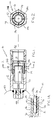
- a relief valve 10 of the invention includes a body 12 defining an axially bore 14 in which a piston 16 is disposed for axial movement.
- the piston 16 defines a circumferential inner shoulder 18 extending about its cuter surface 20, the shoulder having a first camming surface 22.
- an axial sleeve 24 of a suitable eutectic material is mounted within the bore 14, preferably in temperature-conducting contact with the inner wall surface 26 of the bore.
- the piston 16 In use under normal conditions, with the tank 40 (Fig. 1) filled, e.g., with flammable gas at a first pressure differential, wherein pressure at the inlet 44 exceeds pressure at the outlet 42 by at least a predetermined amount, the piston 16 is restricted in a first position to arrest flow of fluid from the inlet 44 towards the outlet 42.
- Movement of the piston 16 towards the second position, i.e., as shown in Fig. 3, is arrested in the first position, i.e., as shown in Fig. 1, by engagement of the opposed camming surfaces 22, 32, thereby arresting the opening movement of the piston 16 and keeping the flow path closed.
- the eutectic material of the sleeve 24 melts, allowing the segments 28a-28d to move radially outward, urged by camming action of surface 22 of the piston 16 upon surface 32 of the restricting elements 28a-28d, thus allowing the piston 16 to move to the second position and opening the flow path for relief of the tank contents.
Landscapes
- Engineering & Computer Science (AREA)
- General Engineering & Computer Science (AREA)
- Mechanical Engineering (AREA)
- Safety Valves (AREA)
- Lift Valve (AREA)
Applications Claiming Priority (2)
| Application Number | Priority Date | Filing Date | Title |
|---|---|---|---|
| US633926 | 1996-04-17 | ||
| US08/633,926 US5743285A (en) | 1996-04-17 | 1996-04-17 | Gas cylinder thermal relief valve |
Publications (2)
| Publication Number | Publication Date |
|---|---|
| EP0802359A2 true EP0802359A2 (de) | 1997-10-22 |
| EP0802359A3 EP0802359A3 (de) | 1998-04-29 |
Family
ID=24541717
Family Applications (1)
| Application Number | Title | Priority Date | Filing Date |
|---|---|---|---|
| EP97400852A Withdrawn EP0802359A3 (de) | 1996-04-17 | 1997-04-15 | Thermisches Druckentlastungsventil für eine Gasflasche |
Country Status (5)
| Country | Link |
|---|---|
| US (1) | US5743285A (de) |
| EP (1) | EP0802359A3 (de) |
| JP (1) | JPH1038113A (de) |
| BR (1) | BR9701840A (de) |
| CA (1) | CA2202809A1 (de) |
Families Citing this family (27)
| Publication number | Priority date | Publication date | Assignee | Title |
|---|---|---|---|---|
| DE4422241A1 (de) * | 1994-06-24 | 1996-01-11 | Mertik Maxitrol Gmbh & Co Kg | Thermische Armaturensicherung zum automatischen Absperren von Leitungen |
| DE19608165C1 (de) * | 1996-03-04 | 1997-11-06 | Mertik Maxitrol Gmbh & Co Kg | Thermische Armaturensicherung zum automatischen Absperren von Leitungen |
| US5941269A (en) * | 1997-04-22 | 1999-08-24 | Gas Research Institute | Pressure relief device |
| DE19810223C1 (de) * | 1998-03-10 | 1999-05-27 | Mertik Maxitrol Gmbh & Co Kg | Thermische Armaturensicherung zum automatischen Absperren von Leitungen |
| JP4593811B2 (ja) * | 2000-03-02 | 2010-12-08 | 株式会社ハマイ | 安全弁及び一体型弁 |
| US6439334B1 (en) | 2000-09-15 | 2002-08-27 | Circle Seal Controls, Inc. | Alternative fuels vehicle and fuel-system valve used therein |
| US6539969B1 (en) | 2000-11-27 | 2003-04-01 | Pursuit Marketing, Inc | Two-piece valve and gas cylinder |
| US6814097B2 (en) | 2001-03-20 | 2004-11-09 | Teleflex Gfi Control Systems L.P. | Pressure relief device |
| KR20030049972A (ko) * | 2001-12-18 | 2003-06-25 | 현대자동차주식회사 | 차량의 씨앤지이 연료 용기의 안전밸브장치 |
| WO2003091612A1 (en) * | 2002-04-23 | 2003-11-06 | Teleflex Gfi Control Systems L.P. | Pressure relief device |
| JP4427371B2 (ja) * | 2004-03-29 | 2010-03-03 | 株式会社ネリキ | 安全弁 |
| DE602005004371T2 (de) * | 2005-02-14 | 2009-02-19 | Luxembourg Patent Company S.A. | Thermisch aktivierbares Sicherheitsventil |
| FR2951239B1 (fr) * | 2009-10-09 | 2011-12-09 | Air Liquide | Dispositif de securite et recipient pourvu d'un tel dispositif |
| US8905055B2 (en) | 2010-05-13 | 2014-12-09 | Water Missions International | Full flow pressure relief valve |
| US8468630B2 (en) | 2010-06-28 | 2013-06-25 | U.W.T., Inc. | Wheel weight tool |
| US8938832B2 (en) | 2010-06-28 | 2015-01-27 | U.W.T. Inc. | Wheel weight tool |
| US8752571B2 (en) | 2010-09-24 | 2014-06-17 | Carl E. Balkus, Jr. | Heating and release valve assembly for a fluid receptacle |
| USD653926S1 (en) | 2011-04-28 | 2012-02-14 | U.W.T., Inc. | Wheel weight tool |
| USD653927S1 (en) | 2011-05-24 | 2012-02-14 | U.W.T., Inc. | Wheel weight removal tool |
| USD685236S1 (en) | 2011-06-27 | 2013-07-02 | U.W.T., Inc. | Heel plate for a wheel weight removal tool |
| US8800587B2 (en) * | 2011-08-05 | 2014-08-12 | GM Global Technology Operations LLC | Thermal pressure relief device |
| USD661959S1 (en) | 2011-10-03 | 2012-06-19 | U.W.T., Inc. | Wheel weight removal hook |
| USD673433S1 (en) | 2011-10-03 | 2013-01-01 | U.W.T., Inc. | Wheel weight removal hook |
| US9044844B1 (en) | 2014-04-10 | 2015-06-02 | U.W.T. Inc. | Wheel weight pliers |
| CN106286922B (zh) * | 2016-10-27 | 2018-08-17 | 泸州江阳超能燃气有限责任公司 | 一种用于压缩天然气减压的减压器 |
| KR102805102B1 (ko) * | 2019-05-17 | 2025-05-08 | 현대자동차주식회사 | 연료전지 차량의 온도감응식 압력안전장치 |
| US11371623B2 (en) | 2019-09-18 | 2022-06-28 | Saudi Arabian Oil Company | Mechanisms and methods for closure of a flow control device |
Family Cites Families (18)
| Publication number | Priority date | Publication date | Assignee | Title |
|---|---|---|---|---|
| US1925007A (en) * | 1930-06-11 | 1933-08-29 | Globe Automatic Sprinkler Co | Fusible unit |
| US1924417A (en) * | 1931-04-11 | 1933-08-29 | James P Ryan | Valve |
| US4164953A (en) * | 1976-12-13 | 1979-08-21 | Conax Corporation | Normally-closed electro-thermally operated flood valve |
| US4245662A (en) * | 1978-10-27 | 1981-01-20 | Combustion Engineering, Inc. | Heat responsive back seat arrangement for valve operator with fusible lock-out cap |
| US4498491A (en) * | 1983-06-08 | 1985-02-12 | The United States Of America As Represented By The Secretary Of The Navy | Thermo-electric valve |
| US4488566A (en) * | 1983-06-22 | 1984-12-18 | The Singer Company | Thermally responsive slam shut valve assembly |
| US4553589A (en) * | 1984-07-12 | 1985-11-19 | Gray Tool Company | Fire-safe surface-controlled subsurface safety valve control line/wellhead connector and blowout preventer |
| DE3817971A1 (de) * | 1988-05-27 | 1989-11-30 | Streif Hans | Gasanschlussarmatur |
| US4827963A (en) * | 1988-10-17 | 1989-05-09 | Cameron Iron Works Usa, Inc. | Heat sensitive shaft locking apparatus and valve using same |
| US4932431A (en) * | 1989-08-07 | 1990-06-12 | Tuthill Corporation | Coupling with heat fusible actuator member |
| US5109881A (en) * | 1990-08-23 | 1992-05-05 | Cooper Industries, Inc. | Temperature sensitive control valve |
| DE9017534U1 (de) * | 1990-12-28 | 1991-03-21 | Streif, Hans, Magliaso, Lugano | Thermische Armaturensicherung |
| US5213128A (en) * | 1991-05-30 | 1993-05-25 | Baird Michael R | Pressure/temperature-activated pressure relief valve |
| US5197671A (en) * | 1991-05-30 | 1993-03-30 | Wass Lloyd G | Pressure relief valve with thermal trigger and movable seal plug |
| US5161738A (en) * | 1991-05-30 | 1992-11-10 | Wass Lloyd G | Pressure and temperature relief valve with thermal trigger |
| US5647390A (en) * | 1995-03-28 | 1997-07-15 | Wass; Lloyd G. | Thermal relief valve with improved bayonet |
| US5562118A (en) * | 1995-07-21 | 1996-10-08 | Pgi International, Ltd. | Emergency shutoff valve with a fusible link and method |
| US5632297A (en) * | 1995-09-26 | 1997-05-27 | Amcast Industrial Corporation | Piston-type thermally or pressure activated relief device |
-
1996
- 1996-04-17 US US08/633,926 patent/US5743285A/en not_active Expired - Lifetime
-
1997
- 1997-04-15 EP EP97400852A patent/EP0802359A3/de not_active Withdrawn
- 1997-04-16 JP JP9099299A patent/JPH1038113A/ja active Pending
- 1997-04-16 CA CA002202809A patent/CA2202809A1/en not_active Abandoned
- 1997-04-17 BR BR9701840A patent/BR9701840A/pt not_active Application Discontinuation
Also Published As
| Publication number | Publication date |
|---|---|
| EP0802359A3 (de) | 1998-04-29 |
| BR9701840A (pt) | 1998-12-01 |
| JPH1038113A (ja) | 1998-02-13 |
| US5743285A (en) | 1998-04-28 |
| CA2202809A1 (en) | 1997-10-17 |
Similar Documents
| Publication | Publication Date | Title |
|---|---|---|
| US5743285A (en) | Gas cylinder thermal relief valve | |
| US4077422A (en) | Flow control means for compressed gas cylinders | |
| US5275194A (en) | Fire control valve with replaceable locking pin assembly | |
| US6810915B2 (en) | Accumulator having a safety valve | |
| US4727903A (en) | Fluid shutoff valve | |
| US20050205140A1 (en) | Combination valve and regulator with vented seat for use with pressurized gas cylinders, particularly oxygen cylinders | |
| US20140034156A1 (en) | Gas filling and dispensing device, vessel with such device, and operational circuit | |
| EP0333687A2 (de) | Fehlersicherer Thermostat für Fahrzeugsysteme | |
| US8596290B2 (en) | Pressure discharge valve for storage tanks | |
| JPH09119539A (ja) | ピストン式熱または圧力反応安全装置 | |
| WO1993023693A1 (en) | Pressure/temperature-activated pressure relief valve | |
| JPH07502324A (ja) | 熱トリガー及び移動自在のシールプラグを備えた圧力逃がし弁 | |
| CA1274225A (en) | Heat sensitive valve | |
| FI95501B (fi) | Palonsulkulaite | |
| US6367500B1 (en) | Safety valve for a compressed-gas tank | |
| CA1321116C (en) | Pressure relief valve | |
| US5941269A (en) | Pressure relief device | |
| EP1418372A1 (de) | Thermisch aktivierbares Sicherheitsventil | |
| US4899777A (en) | Thermally activated pressure relief plug | |
| US5551470A (en) | Thermally responsive pressure relief apparatus | |
| US4225760A (en) | Pressure actuated unit with high temperature protection | |
| EP0088077B1 (de) | Feuersicherheitsventil | |
| JPS6318866Y2 (de) | ||
| US6276389B1 (en) | Toxic fluid safe relief valve | |
| KR200256637Y1 (ko) | 화재시 안전밸브 |
Legal Events
| Date | Code | Title | Description |
|---|---|---|---|
| PUAI | Public reference made under article 153(3) epc to a published international application that has entered the european phase |
Free format text: ORIGINAL CODE: 0009012 |
|
| AK | Designated contracting states |
Kind code of ref document: A2 Designated state(s): AT DE FR GB IT |
|
| PUAL | Search report despatched |
Free format text: ORIGINAL CODE: 0009013 |
|
| AK | Designated contracting states |
Kind code of ref document: A3 Designated state(s): AT DE FR GB IT |
|
| 17P | Request for examination filed |
Effective date: 19980620 |
|
| 17Q | First examination report despatched |
Effective date: 19991217 |
|
| STAA | Information on the status of an ep patent application or granted ep patent |
Free format text: STATUS: THE APPLICATION IS DEEMED TO BE WITHDRAWN |
|
| 18D | Application deemed to be withdrawn |
Effective date: 20000428 |