EP0802338B1 - Verfahren zur Herstellung einer gerollten Metall/Kunstoff-Verbundbuchse - Google Patents
Verfahren zur Herstellung einer gerollten Metall/Kunstoff-Verbundbuchse Download PDFInfo
- Publication number
- EP0802338B1 EP0802338B1 EP97105756A EP97105756A EP0802338B1 EP 0802338 B1 EP0802338 B1 EP 0802338B1 EP 97105756 A EP97105756 A EP 97105756A EP 97105756 A EP97105756 A EP 97105756A EP 0802338 B1 EP0802338 B1 EP 0802338B1
- Authority
- EP
- European Patent Office
- Prior art keywords
- sleeve
- plastic
- plastics material
- plate
- rolled metal
- Prior art date
- Legal status (The legal status is an assumption and is not a legal conclusion. Google has not performed a legal analysis and makes no representation as to the accuracy of the status listed.)
- Expired - Lifetime
Links
- 239000004033 plastic Substances 0.000 title claims abstract description 34
- 229920003023 plastic Polymers 0.000 title claims abstract description 34
- 239000002184 metal Substances 0.000 title claims abstract description 12
- 238000004519 manufacturing process Methods 0.000 title claims description 9
- 238000001746 injection moulding Methods 0.000 claims abstract description 13
- 238000007789 sealing Methods 0.000 claims abstract description 4
- 238000001721 transfer moulding Methods 0.000 claims abstract description 3
- 239000002131 composite material Substances 0.000 claims description 13
- 238000000034 method Methods 0.000 claims description 13
- 239000000463 material Substances 0.000 claims description 6
- 239000007924 injection Substances 0.000 claims description 2
- 239000011248 coating agent Substances 0.000 claims 2
- 238000000576 coating method Methods 0.000 claims 2
- 239000007858 starting material Substances 0.000 claims 2
- 238000007373 indentation Methods 0.000 claims 1
- 238000002347 injection Methods 0.000 claims 1
- 239000010410 layer Substances 0.000 description 13
- 238000005507 spraying Methods 0.000 description 4
- 238000001816 cooling Methods 0.000 description 3
- 239000000314 lubricant Substances 0.000 description 3
- 239000004810 polytetrafluoroethylene Substances 0.000 description 3
- 229920001343 polytetrafluoroethylene Polymers 0.000 description 3
- 229910001369 Brass Inorganic materials 0.000 description 2
- 239000010951 brass Substances 0.000 description 2
- 239000004519 grease Substances 0.000 description 2
- 238000012423 maintenance Methods 0.000 description 2
- 229920001707 polybutylene terephthalate Polymers 0.000 description 2
- 238000012360 testing method Methods 0.000 description 2
- 229910000760 Hardened steel Inorganic materials 0.000 description 1
- 239000004952 Polyamide Substances 0.000 description 1
- 238000005452 bending Methods 0.000 description 1
- 230000015572 biosynthetic process Effects 0.000 description 1
- 230000000052 comparative effect Effects 0.000 description 1
- 238000010276 construction Methods 0.000 description 1
- 230000002349 favourable effect Effects 0.000 description 1
- 238000010102 injection blow moulding Methods 0.000 description 1
- 230000007774 longterm Effects 0.000 description 1
- 238000005461 lubrication Methods 0.000 description 1
- 238000011089 mechanical engineering Methods 0.000 description 1
- 239000007769 metal material Substances 0.000 description 1
- 229920002647 polyamide Polymers 0.000 description 1
- -1 polybutylene terephthalate Polymers 0.000 description 1
- 229920000642 polymer Polymers 0.000 description 1
- 238000012805 post-processing Methods 0.000 description 1
- 239000002994 raw material Substances 0.000 description 1
- 238000005096 rolling process Methods 0.000 description 1
- 239000012791 sliding layer Substances 0.000 description 1
- 239000007787 solid Substances 0.000 description 1
- 239000007921 spray Substances 0.000 description 1
- 238000003860 storage Methods 0.000 description 1
- 239000000126 substance Substances 0.000 description 1
Images


Classifications
-
- F—MECHANICAL ENGINEERING; LIGHTING; HEATING; WEAPONS; BLASTING
- F16—ENGINEERING ELEMENTS AND UNITS; GENERAL MEASURES FOR PRODUCING AND MAINTAINING EFFECTIVE FUNCTIONING OF MACHINES OR INSTALLATIONS; THERMAL INSULATION IN GENERAL
- F16C—SHAFTS; FLEXIBLE SHAFTS; ELEMENTS OR CRANKSHAFT MECHANISMS; ROTARY BODIES OTHER THAN GEARING ELEMENTS; BEARINGS
- F16C33/00—Parts of bearings; Special methods for making bearings or parts thereof
- F16C33/02—Parts of sliding-contact bearings
- F16C33/04—Brasses; Bushes; Linings
- F16C33/20—Sliding surface consisting mainly of plastics
- F16C33/201—Composition of the plastic
-
- B—PERFORMING OPERATIONS; TRANSPORTING
- B29—WORKING OF PLASTICS; WORKING OF SUBSTANCES IN A PLASTIC STATE IN GENERAL
- B29C—SHAPING OR JOINING OF PLASTICS; SHAPING OF MATERIAL IN A PLASTIC STATE, NOT OTHERWISE PROVIDED FOR; AFTER-TREATMENT OF THE SHAPED PRODUCTS, e.g. REPAIRING
- B29C37/00—Component parts, details, accessories or auxiliary operations, not covered by group B29C33/00 or B29C35/00
- B29C37/0078—Measures or configurations for obtaining anchoring effects in the contact areas between layers
- B29C37/0082—Mechanical anchoring
- B29C37/0085—Mechanical anchoring by means of openings in the layers
-
- B—PERFORMING OPERATIONS; TRANSPORTING
- B29—WORKING OF PLASTICS; WORKING OF SUBSTANCES IN A PLASTIC STATE IN GENERAL
- B29C—SHAPING OR JOINING OF PLASTICS; SHAPING OF MATERIAL IN A PLASTIC STATE, NOT OTHERWISE PROVIDED FOR; AFTER-TREATMENT OF THE SHAPED PRODUCTS, e.g. REPAIRING
- B29C45/00—Injection moulding, i.e. forcing the required volume of moulding material through a nozzle into a closed mould; Apparatus therefor
- B29C45/14—Injection moulding, i.e. forcing the required volume of moulding material through a nozzle into a closed mould; Apparatus therefor incorporating preformed parts or layers, e.g. injection moulding around inserts or for coating articles
- B29C45/14336—Coating a portion of the article, e.g. the edge of the article
- B29C45/14344—Moulding in or through a hole in the article, e.g. outsert moulding
-
- F—MECHANICAL ENGINEERING; LIGHTING; HEATING; WEAPONS; BLASTING
- F16—ENGINEERING ELEMENTS AND UNITS; GENERAL MEASURES FOR PRODUCING AND MAINTAINING EFFECTIVE FUNCTIONING OF MACHINES OR INSTALLATIONS; THERMAL INSULATION IN GENERAL
- F16C—SHAFTS; FLEXIBLE SHAFTS; ELEMENTS OR CRANKSHAFT MECHANISMS; ROTARY BODIES OTHER THAN GEARING ELEMENTS; BEARINGS
- F16C17/00—Sliding-contact bearings for exclusively rotary movement
- F16C17/02—Sliding-contact bearings for exclusively rotary movement for radial load only
-
- F—MECHANICAL ENGINEERING; LIGHTING; HEATING; WEAPONS; BLASTING
- F16—ENGINEERING ELEMENTS AND UNITS; GENERAL MEASURES FOR PRODUCING AND MAINTAINING EFFECTIVE FUNCTIONING OF MACHINES OR INSTALLATIONS; THERMAL INSULATION IN GENERAL
- F16C—SHAFTS; FLEXIBLE SHAFTS; ELEMENTS OR CRANKSHAFT MECHANISMS; ROTARY BODIES OTHER THAN GEARING ELEMENTS; BEARINGS
- F16C33/00—Parts of bearings; Special methods for making bearings or parts thereof
- F16C33/02—Parts of sliding-contact bearings
- F16C33/04—Brasses; Bushes; Linings
- F16C33/20—Sliding surface consisting mainly of plastics
- F16C33/203—Multilayer structures, e.g. sleeves comprising a plastic lining
- F16C33/205—Multilayer structures, e.g. sleeves comprising a plastic lining with two layers
-
- F—MECHANICAL ENGINEERING; LIGHTING; HEATING; WEAPONS; BLASTING
- F16—ENGINEERING ELEMENTS AND UNITS; GENERAL MEASURES FOR PRODUCING AND MAINTAINING EFFECTIVE FUNCTIONING OF MACHINES OR INSTALLATIONS; THERMAL INSULATION IN GENERAL
- F16C—SHAFTS; FLEXIBLE SHAFTS; ELEMENTS OR CRANKSHAFT MECHANISMS; ROTARY BODIES OTHER THAN GEARING ELEMENTS; BEARINGS
- F16C33/00—Parts of bearings; Special methods for making bearings or parts thereof
- F16C33/02—Parts of sliding-contact bearings
- F16C33/04—Brasses; Bushes; Linings
- F16C33/20—Sliding surface consisting mainly of plastics
- F16C33/208—Methods of manufacture, e.g. shaping, applying coatings
-
- F—MECHANICAL ENGINEERING; LIGHTING; HEATING; WEAPONS; BLASTING
- F16—ENGINEERING ELEMENTS AND UNITS; GENERAL MEASURES FOR PRODUCING AND MAINTAINING EFFECTIVE FUNCTIONING OF MACHINES OR INSTALLATIONS; THERMAL INSULATION IN GENERAL
- F16C—SHAFTS; FLEXIBLE SHAFTS; ELEMENTS OR CRANKSHAFT MECHANISMS; ROTARY BODIES OTHER THAN GEARING ELEMENTS; BEARINGS
- F16C43/00—Assembling bearings
- F16C43/02—Assembling sliding-contact bearings
-
- B—PERFORMING OPERATIONS; TRANSPORTING
- B29—WORKING OF PLASTICS; WORKING OF SUBSTANCES IN A PLASTIC STATE IN GENERAL
- B29C—SHAPING OR JOINING OF PLASTICS; SHAPING OF MATERIAL IN A PLASTIC STATE, NOT OTHERWISE PROVIDED FOR; AFTER-TREATMENT OF THE SHAPED PRODUCTS, e.g. REPAIRING
- B29C45/00—Injection moulding, i.e. forcing the required volume of moulding material through a nozzle into a closed mould; Apparatus therefor
- B29C45/14—Injection moulding, i.e. forcing the required volume of moulding material through a nozzle into a closed mould; Apparatus therefor incorporating preformed parts or layers, e.g. injection moulding around inserts or for coating articles
- B29C45/14311—Injection moulding, i.e. forcing the required volume of moulding material through a nozzle into a closed mould; Apparatus therefor incorporating preformed parts or layers, e.g. injection moulding around inserts or for coating articles using means for bonding the coating to the articles
-
- B—PERFORMING OPERATIONS; TRANSPORTING
- B29—WORKING OF PLASTICS; WORKING OF SUBSTANCES IN A PLASTIC STATE IN GENERAL
- B29K—INDEXING SCHEME ASSOCIATED WITH SUBCLASSES B29B, B29C OR B29D, RELATING TO MOULDING MATERIALS OR TO MATERIALS FOR MOULDS, REINFORCEMENTS, FILLERS OR PREFORMED PARTS, e.g. INSERTS
- B29K2705/00—Use of metals, their alloys or their compounds, for preformed parts, e.g. for inserts
-
- B—PERFORMING OPERATIONS; TRANSPORTING
- B29—WORKING OF PLASTICS; WORKING OF SUBSTANCES IN A PLASTIC STATE IN GENERAL
- B29L—INDEXING SCHEME ASSOCIATED WITH SUBCLASS B29C, RELATING TO PARTICULAR ARTICLES
- B29L2031/00—Other particular articles
- B29L2031/04—Bearings
-
- F—MECHANICAL ENGINEERING; LIGHTING; HEATING; WEAPONS; BLASTING
- F16—ENGINEERING ELEMENTS AND UNITS; GENERAL MEASURES FOR PRODUCING AND MAINTAINING EFFECTIVE FUNCTIONING OF MACHINES OR INSTALLATIONS; THERMAL INSULATION IN GENERAL
- F16C—SHAFTS; FLEXIBLE SHAFTS; ELEMENTS OR CRANKSHAFT MECHANISMS; ROTARY BODIES OTHER THAN GEARING ELEMENTS; BEARINGS
- F16C2208/00—Plastics; Synthetic resins, e.g. rubbers
- F16C2208/20—Thermoplastic resins
- F16C2208/70—Polyesters, e.g. polyethylene-terephthlate [PET], polybutylene-terephthlate [PBT]
-
- F—MECHANICAL ENGINEERING; LIGHTING; HEATING; WEAPONS; BLASTING
- F16—ENGINEERING ELEMENTS AND UNITS; GENERAL MEASURES FOR PRODUCING AND MAINTAINING EFFECTIVE FUNCTIONING OF MACHINES OR INSTALLATIONS; THERMAL INSULATION IN GENERAL
- F16C—SHAFTS; FLEXIBLE SHAFTS; ELEMENTS OR CRANKSHAFT MECHANISMS; ROTARY BODIES OTHER THAN GEARING ELEMENTS; BEARINGS
- F16C2220/00—Shaping
- F16C2220/02—Shaping by casting
- F16C2220/04—Shaping by casting by injection-moulding
-
- F—MECHANICAL ENGINEERING; LIGHTING; HEATING; WEAPONS; BLASTING
- F16—ENGINEERING ELEMENTS AND UNITS; GENERAL MEASURES FOR PRODUCING AND MAINTAINING EFFECTIVE FUNCTIONING OF MACHINES OR INSTALLATIONS; THERMAL INSULATION IN GENERAL
- F16C—SHAFTS; FLEXIBLE SHAFTS; ELEMENTS OR CRANKSHAFT MECHANISMS; ROTARY BODIES OTHER THAN GEARING ELEMENTS; BEARINGS
- F16C2226/00—Joining parts; Fastening; Assembling or mounting parts
- F16C2226/30—Material joints
-
- F—MECHANICAL ENGINEERING; LIGHTING; HEATING; WEAPONS; BLASTING
- F16—ENGINEERING ELEMENTS AND UNITS; GENERAL MEASURES FOR PRODUCING AND MAINTAINING EFFECTIVE FUNCTIONING OF MACHINES OR INSTALLATIONS; THERMAL INSULATION IN GENERAL
- F16C—SHAFTS; FLEXIBLE SHAFTS; ELEMENTS OR CRANKSHAFT MECHANISMS; ROTARY BODIES OTHER THAN GEARING ELEMENTS; BEARINGS
- F16C2226/00—Joining parts; Fastening; Assembling or mounting parts
- F16C2226/50—Positive connections
- F16C2226/70—Positive connections with complementary interlocking parts
- F16C2226/76—Positive connections with complementary interlocking parts with tongue and groove or key and slot
- F16C2226/78—Positive connections with complementary interlocking parts with tongue and groove or key and slot of jigsaw-puzzle type
-
- F—MECHANICAL ENGINEERING; LIGHTING; HEATING; WEAPONS; BLASTING
- F16—ENGINEERING ELEMENTS AND UNITS; GENERAL MEASURES FOR PRODUCING AND MAINTAINING EFFECTIVE FUNCTIONING OF MACHINES OR INSTALLATIONS; THERMAL INSULATION IN GENERAL
- F16C—SHAFTS; FLEXIBLE SHAFTS; ELEMENTS OR CRANKSHAFT MECHANISMS; ROTARY BODIES OTHER THAN GEARING ELEMENTS; BEARINGS
- F16C2300/00—Application independent of particular apparatuses
- F16C2300/02—General use or purpose, i.e. no use, purpose, special adaptation or modification indicated or a wide variety of uses mentioned
Definitions
- the invention relates to a method for producing a rolled metal / plastic composite bushing.
- the invention is based on the object To manufacture the composite bushing more cost-effectively and at the same time expensive post-processing steps such. B. calibrating to finished dimensions or attaching more Construction features such as joints, sealing lips, grooves etc. inexpensively in the "normal" manufacturing process integrate.
- the spray pressure settles at the same time the round-shaped bushing on the mold and creates an additional tolerance improvement on the outer diameter the hosed bush.
- the ends of the bushing are clamped together so that it can be easily inserted into the injection molding / injection molding machine.
- the board is rounded with the punch feed to the outside.
- the method according to the invention opens up the possibility of Sealing lips made of the plastic used to be injected on both sides of the socket, so that protection of the There is a socket against incoming foreign substances and at the same time the lubricant (e.g. grease) remains in the bearings.
- a separate seal can be used to be dispensed with.
- structures can continue to enter the Surface of the inner running layer such as Grooves, compensation chamfers or the like. The more expensive subsequent production is not necessary.
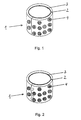
- a finished metal / plastic composite bushing 1 consisting of an outer metal support 2 and a running layer 3 made of plastic, in holes 4 of the metal support 2 is held.
- Bronzes are preferably used as the metal carrier 2 or related brass, which also after the Wear of the plastic layer is still a lot Represent good plain bearing material as a running partner.
- inner running layer 3 are suitable for all plastics with sliding bearing properties, the preferred to achieve freedom from maintenance or low maintenance with solid lubricants in Form of PTFE or the like are modified.
- Fig. 2 shows a further embodiment of the composite bush 1, in which the ends of the metal carrier 2 are clamped together are.
- Fig. 3 shows schematically the manufacture of an inventive Composite bushing 1.
- a metallic Board 5 with holes 4 according to Fig. 3a which is already wide B and length L of the finished bushing 1 is cut the board 5 is subjected to a round deformation according to FIG. 3b, so that the holes 4 are conically deformed towards the center of the socket become.
- the final spraying takes place the running layer 3 in one indicated by number 6 Injection / transfer molding machine.
- a shaft made of hardened steel served as counter-rotating partner with an outer diameter of 30 mm.
- For initial lubrication served a Li-saponified grease.
Landscapes
- Engineering & Computer Science (AREA)
- General Engineering & Computer Science (AREA)
- Mechanical Engineering (AREA)
- Manufacturing & Machinery (AREA)
- Injection Moulding Of Plastics Or The Like (AREA)
- Sliding-Contact Bearings (AREA)
- Laminated Bodies (AREA)
Description
Zur weiteren Verbesserung der Verklammerung des Kunststoffes in den Löchern wird die Platine mit dem Stanzeinzug nach außen rundgeformt.
- Fig. 1
- eine erfindungsgemäße Metall/Kunststoff-Verbundbuchse,
- Fig. 2
- eine weitere Ausführungsform einer erfindungsgemäßen Verbundbuchse,
- Fig. 3
- schematisch die Herstellung der erfindungsgemäßen Verbundbuchse,
- Fig. 4
- die Schwindung des Kunststoffs bei der Abkühlung und
- Fig. 5
- eine Anordnung von Fasen bei der Kunststoffschicht.
Claims (5)
- Verfahren zur Herstellung einer gerollten Metall/Kunststoff-Verbundbuchse (1) mit den folgenden Verfahrensschritten in folgender Reihenfolge:a) Zuschneiden eines metallischen Vormaterialbandes auf Breite B der Buchse (1),b) Lochen des bereits auf Breite B zugeschnittenen Vormaterialbandes,c) Ablängen auf Länge L, der Buchse (1) zur Bildung einer Platine (5),d) Rundformen der Platine (5) zur Buchse (1),e) Ausfüllen der Löcher (4) mit Kunststoff unter gleichzeitiger Ausbildung einer inneren Laufschicht (3) mit formschlüssiger Halterung des Kunststoffes in den konisch zur Buchsenmitte hin verformten Löchern (4), mitels Ausspritzung der rundgeformten Buchse (1) mit Kunststoff in einer Spritzgieß-/Spritzpreßmaschine (6) bei einer dem jeweiligen Kunststoff angepaßten Temperatur.
- Verfahren nach Anspruch 1, dadurch gekennzeichnet, daß die Enden der Buchse (1) miteinander verklammert sind.
- Verfahren nach Anspruch 1 oder 2, dadurch gekennzeichnet, daß die Platine (5) mit dem Stanzeinzug nach außen rundgeformt wird.
- Verfahren nach einem oder mehreren der Ansprüche 1 bis 3, dadurch gekennzeichnet, daß an die Buchse (1) beidseitig Dichtungslippen aus dem verwendeten Kunststoff angespritzt werden.
- Verfahren nach einem oder mehreren der Ansprüche 1 bis 4, dadurch gekennzeichnet, daß beim Anspritzvorgang gleichzeitig in der Oberfläche der inneren Laufschicht (3) Strukturen, wie etwa Nuten, Ausgleichsfasen (7) oder dgl. ausgebildet werden.
Applications Claiming Priority (2)
| Application Number | Priority Date | Filing Date | Title |
|---|---|---|---|
| DE19615757 | 1996-04-20 | ||
| DE19615757A DE19615757C2 (de) | 1996-04-20 | 1996-04-20 | Verfahren zur Herstellung einer Lagerbuchse als gerollte Metall/Kunststoff-Verbundbuchse |
Publications (3)
| Publication Number | Publication Date |
|---|---|
| EP0802338A2 EP0802338A2 (de) | 1997-10-22 |
| EP0802338A3 EP0802338A3 (de) | 1998-09-02 |
| EP0802338B1 true EP0802338B1 (de) | 2003-09-24 |
Family
ID=7791922
Family Applications (1)
| Application Number | Title | Priority Date | Filing Date |
|---|---|---|---|
| EP97105756A Expired - Lifetime EP0802338B1 (de) | 1996-04-20 | 1997-04-08 | Verfahren zur Herstellung einer gerollten Metall/Kunstoff-Verbundbuchse |
Country Status (3)
| Country | Link |
|---|---|
| EP (1) | EP0802338B1 (de) |
| AT (1) | ATE250725T1 (de) |
| DE (2) | DE19615757C2 (de) |
Cited By (2)
| Publication number | Priority date | Publication date | Assignee | Title |
|---|---|---|---|---|
| DE102004060258B3 (de) * | 2004-12-15 | 2006-03-02 | Federal-Mogul Deva Gmbh | Gleitlagerelement und Verfahren zur Herstellung einer gerollten Gleitlagerbuchse |
| US10207438B2 (en) | 2014-01-31 | 2019-02-19 | Sumitomo Electric Industries, Ltd. | Composite member and composite-member manufacturing method |
Families Citing this family (11)
| Publication number | Priority date | Publication date | Assignee | Title |
|---|---|---|---|---|
| DE19754705A1 (de) * | 1997-12-10 | 1999-06-17 | Skf Gleitlager Gmbh | Verfahren zum Herstellen eines Verbundgleitlagers und danach hergestelltes Verbundgleitlager |
| DE19907571A1 (de) | 1999-02-23 | 2000-09-14 | Ks Gleitlager Gmbh | Gerollte Gleitlagerbuchse |
| DE10011651B4 (de) | 2000-03-10 | 2009-12-24 | Schaeffler Kg | Rotationssymmetrisches Formteil |
| DE10240282B4 (de) * | 2002-08-31 | 2011-08-11 | Schaeffler Technologies GmbH & Co. KG, 91074 | Radialwälzlager |
| DE102006059329B4 (de) * | 2006-12-15 | 2009-01-15 | Magna Car Top Systems Gmbh | Lagerbuchse |
| EP2400175A1 (de) | 2010-06-24 | 2011-12-28 | KS Gleitlager GmbH | Verfahren zum Herstellen eines Gleitlagerelements |
| DE102011087530A1 (de) * | 2011-12-01 | 2013-06-06 | Ks Gleitlager Gmbh | Flachmaterialabschnitt für die Herstellung eines buchsenförmigen Gleitlagerelements sowie Gleitlagerbuchse |
| SE1550424A1 (en) | 2015-04-09 | 2016-10-10 | Scania Cv Ab | An injection-molded article comprising a bushing |
| WO2017024859A1 (zh) * | 2015-08-10 | 2017-02-16 | 大连三环复合材料技术开发股份有限公司 | 核主泵水润滑复合材料推力轴承 |
| CN110039709A (zh) * | 2019-04-04 | 2019-07-23 | 歌尔股份有限公司 | 注塑产品的成型方法及注塑产品 |
| DE102022201778A1 (de) | 2022-02-21 | 2023-08-24 | Mahle International Gmbh | Verfahren zur Herstellung einer Buchse |
Citations (2)
| Publication number | Priority date | Publication date | Assignee | Title |
|---|---|---|---|---|
| US3008779A (en) * | 1959-06-03 | 1961-11-14 | John D Spriggs | Nylon lined bearings |
| EP0635106A1 (de) * | 1992-04-09 | 1995-01-25 | Thore Rabe | Verfahren zur herstellung eines hülsenförmigen gleitlagers und nach diesem verfahren hergestelltes gleitlager. |
Family Cites Families (10)
| Publication number | Priority date | Publication date | Assignee | Title |
|---|---|---|---|---|
| FR1342927A (fr) * | 1963-11-04 | 1963-11-15 | Procédé de surmoulage de pièces injectées | |
| DE1904625U (de) * | 1963-11-28 | 1964-11-19 | Linnepe & Schiffer | Gefaess, wie vase, becher od. dgl. |
| US3628589A (en) * | 1968-01-31 | 1971-12-21 | Time Inc | Flow systems |
| GB1388116A (en) * | 1971-08-04 | 1975-03-19 | Durward Clarkson Co Ltd | Bearing bushes |
| US4106962A (en) * | 1977-07-14 | 1978-08-15 | Ncr Corporation | Method of fastening metal part to plastic part |
| JPS6188022A (ja) * | 1985-10-07 | 1986-05-06 | Sutaaraito Kogyo Kk | 軸受の製造法 |
| JPS62266217A (ja) * | 1986-05-09 | 1987-11-19 | Daido Metal Kogyo Kk | ブシユ |
| JPS63195415A (ja) * | 1987-02-05 | 1988-08-12 | Daido Metal Kogyo Kk | 少なくとも2つの合わせ目を有する雌雄締結形ブシユ軸受 |
| GB9208782D0 (en) * | 1992-04-23 | 1992-06-10 | Lee Donald A | Friction reduction for slideways |
| GB2270720B (en) * | 1992-09-17 | 1996-01-10 | T & N Technology Ltd | Manufacturing plain bearing materials |
-
1996
- 1996-04-20 DE DE19615757A patent/DE19615757C2/de not_active Expired - Fee Related
-
1997
- 1997-04-08 DE DE59710765T patent/DE59710765D1/de not_active Expired - Lifetime
- 1997-04-08 AT AT97105756T patent/ATE250725T1/de active
- 1997-04-08 EP EP97105756A patent/EP0802338B1/de not_active Expired - Lifetime
Patent Citations (2)
| Publication number | Priority date | Publication date | Assignee | Title |
|---|---|---|---|---|
| US3008779A (en) * | 1959-06-03 | 1961-11-14 | John D Spriggs | Nylon lined bearings |
| EP0635106A1 (de) * | 1992-04-09 | 1995-01-25 | Thore Rabe | Verfahren zur herstellung eines hülsenförmigen gleitlagers und nach diesem verfahren hergestelltes gleitlager. |
Non-Patent Citations (2)
| Title |
|---|
| Prospekt: "HL Wartungsfreie Gleitlager, Kurzinformation", Glacier Industrial Bearings * |
| Prospekt: "VBK Kunststoff-Verbundbuchsen für Gleitlager", Ausgabe 1991, Wieland-Werke AG * |
Cited By (4)
| Publication number | Priority date | Publication date | Assignee | Title |
|---|---|---|---|---|
| DE102004060258B3 (de) * | 2004-12-15 | 2006-03-02 | Federal-Mogul Deva Gmbh | Gleitlagerelement und Verfahren zur Herstellung einer gerollten Gleitlagerbuchse |
| EP1671718A1 (de) | 2004-12-15 | 2006-06-21 | Federal-Mogul Deva GmbH | Gleitlagerelement und Verfahren zur Herstellung einer gerollten Gleitlagerbuchse |
| CN100542734C (zh) * | 2004-12-15 | 2009-09-23 | 联邦-莫戈尔迪瓦有限公司 | 滑动轴承元件和制造卷制的滑动轴承衬套的方法 |
| US10207438B2 (en) | 2014-01-31 | 2019-02-19 | Sumitomo Electric Industries, Ltd. | Composite member and composite-member manufacturing method |
Also Published As
| Publication number | Publication date |
|---|---|
| DE59710765D1 (de) | 2003-10-30 |
| DE19615757A1 (de) | 1997-10-23 |
| DE19615757C2 (de) | 2001-10-18 |
| EP0802338A2 (de) | 1997-10-22 |
| ATE250725T1 (de) | 2003-10-15 |
| EP0802338A3 (de) | 1998-09-02 |
Similar Documents
| Publication | Publication Date | Title |
|---|---|---|
| EP0802338B1 (de) | Verfahren zur Herstellung einer gerollten Metall/Kunstoff-Verbundbuchse | |
| DE3823084C2 (de) | ||
| DE69414758T2 (de) | Zusammensetzter Verbundstoff und Verfahren zu seiner Herstellung | |
| DE102007015615A1 (de) | Verbindungsstück zum gelenkigen Verbinden von im Fahrwerk eines Fahrzeugs angeordneten Bauelementen | |
| CH660212A5 (de) | Verfahren zum herstellen eines kugelgelenkes. | |
| EP1287944A2 (de) | Verfahren zum Herstellen eines Hohlkolbens für eine Kolbenmaschine | |
| EP1929146B8 (de) | Verfahren zur herstellung eines kolbens für einen verbrennungsmotor sowie danach hergestellter kolben | |
| EP1566579A2 (de) | Vorrichtung zur Übertragung von Schaltbewegungen in einem Kraftfahrzeug-Schaltgetriebe und Verfahren zu deren Herstellung | |
| DE2052513A1 (de) | Scharnier mit wartungsfrei gelagertem Scharnierstift und Verfahren zu seiner Herstellung | |
| DE3015430A1 (de) | Lineare kugellagereinheit und verfahren zum herstellen derselben | |
| DE102007009322A1 (de) | Gelenkzapfen aus Metall für den Einsatz in axial und/oder radial belasteten Kraftfahrzeug-Fahrwerksgelenken und Verfahren zu seiner Herstellung | |
| DE102010042849B4 (de) | Lagerkäfig und Verfahren zur Herstellung desselben | |
| DE10206169B4 (de) | Verfahren zum Herstellen eines Plastifizierzylinders mit Innenbeschichtung | |
| DE10246726A1 (de) | Verfahren zur Herstellung einer Drosselklappe in einem durchgehenden Drosselklappenstutzen | |
| DE102010007791B4 (de) | Verfahren zur Herstellung eines Gelenklagers und Gelenklager | |
| DE10220419A1 (de) | Zylinderrollenlager | |
| DE102007058573A1 (de) | Synchronisationseinrichtung für ein Wechselgetriebe und Verfahren zur Herstellung eines Synchronrings für eine Synchronisationseinrichtung eines Wechselgetriebes | |
| EP1357306A1 (de) | Kugelzapfen mit angespritzter Kugel aus Kunstoff | |
| DE19757021A1 (de) | Lagerbuchse und Verfahren zu ihrer Herstellung | |
| DE19843277B4 (de) | Laufrolle aus Kunststoff und Verfahren zur Herstellung | |
| DE102006017373B4 (de) | Kaltumformverfahren zur Herstellung eines einbaufertigen Kugelzapfens | |
| EP4283838B1 (de) | Rotoraufnahme zur herstellung einer verbindung einer welle mit einem rotorblechpaket für einen rotor eines innenläufermotors | |
| DE102021205347B3 (de) | Elastomerverbundlager, Lageranordnung und Verfahren zur Herstellung einer Außenhülse eines Elastomerverbundlagers | |
| AT501607B1 (de) | Buchse aus kunststoff | |
| DE102005006673A1 (de) | Verfahren zur Herstellung eines Metallteiles eines Kunststoff-Metall-Verbundteiles und ein nach dem Verfahren hergestelltes Metallteil |
Legal Events
| Date | Code | Title | Description |
|---|---|---|---|
| PUAI | Public reference made under article 153(3) epc to a published international application that has entered the european phase |
Free format text: ORIGINAL CODE: 0009012 |
|
| 17P | Request for examination filed |
Effective date: 19970408 |
|
| AK | Designated contracting states |
Kind code of ref document: A2 Designated state(s): AT CH DE FI FR GB IT LI SE |
|
| PUAL | Search report despatched |
Free format text: ORIGINAL CODE: 0009013 |
|
| AK | Designated contracting states |
Kind code of ref document: A3 Designated state(s): AT CH DE FI FR GB IT LI SE |
|
| 17Q | First examination report despatched |
Effective date: 19991228 |
|
| GRAH | Despatch of communication of intention to grant a patent |
Free format text: ORIGINAL CODE: EPIDOS IGRA |
|
| GRAS | Grant fee paid |
Free format text: ORIGINAL CODE: EPIDOSNIGR3 |
|
| GRAA | (expected) grant |
Free format text: ORIGINAL CODE: 0009210 |
|
| AK | Designated contracting states |
Kind code of ref document: B1 Designated state(s): AT CH DE FI FR GB IT LI SE |
|
| REG | Reference to a national code |
Ref country code: GB Ref legal event code: FG4D Free format text: NOT ENGLISH |
|
| REG | Reference to a national code |
Ref country code: CH Ref legal event code: EP |
|
| REF | Corresponds to: |
Ref document number: 59710765 Country of ref document: DE Date of ref document: 20031030 Kind code of ref document: P |
|
| REG | Reference to a national code |
Ref country code: SE Ref legal event code: TRGR |
|
| GBT | Gb: translation of ep patent filed (gb section 77(6)(a)/1977) |
Effective date: 20040104 |
|
| ET | Fr: translation filed | ||
| PLBE | No opposition filed within time limit |
Free format text: ORIGINAL CODE: 0009261 |
|
| STAA | Information on the status of an ep patent application or granted ep patent |
Free format text: STATUS: NO OPPOSITION FILED WITHIN TIME LIMIT |
|
| 26N | No opposition filed |
Effective date: 20040625 |
|
| REG | Reference to a national code |
Ref country code: CH Ref legal event code: PFA Owner name: WIELAND-WERKE AG Free format text: WIELAND-WERKE AG#GRAF-ARCO-STRASSE 36#89070 ULM (DE) -TRANSFER TO- WIELAND-WERKE AG#GRAF-ARCO-STRASSE 36#89070 ULM (DE) |
|
| PGFP | Annual fee paid to national office [announced via postgrant information from national office to epo] |
Ref country code: CH Payment date: 20120412 Year of fee payment: 16 Ref country code: DE Payment date: 20120430 Year of fee payment: 16 |
|
| PGFP | Annual fee paid to national office [announced via postgrant information from national office to epo] |
Ref country code: FR Payment date: 20120504 Year of fee payment: 16 Ref country code: GB Payment date: 20120404 Year of fee payment: 16 Ref country code: FI Payment date: 20120411 Year of fee payment: 16 Ref country code: SE Payment date: 20120411 Year of fee payment: 16 |
|
| PGFP | Annual fee paid to national office [announced via postgrant information from national office to epo] |
Ref country code: IT Payment date: 20120419 Year of fee payment: 16 |
|
| PGFP | Annual fee paid to national office [announced via postgrant information from national office to epo] |
Ref country code: AT Payment date: 20120327 Year of fee payment: 16 |
|
| REG | Reference to a national code |
Ref country code: CH Ref legal event code: PL |
|
| REG | Reference to a national code |
Ref country code: SE Ref legal event code: EUG |
|
| REG | Reference to a national code |
Ref country code: AT Ref legal event code: MM01 Ref document number: 250725 Country of ref document: AT Kind code of ref document: T Effective date: 20130430 |
|
| GBPC | Gb: european patent ceased through non-payment of renewal fee |
Effective date: 20130408 |
|
| PG25 | Lapsed in a contracting state [announced via postgrant information from national office to epo] |
Ref country code: CH Free format text: LAPSE BECAUSE OF NON-PAYMENT OF DUE FEES Effective date: 20130430 Ref country code: GB Free format text: LAPSE BECAUSE OF NON-PAYMENT OF DUE FEES Effective date: 20130408 Ref country code: SE Free format text: LAPSE BECAUSE OF NON-PAYMENT OF DUE FEES Effective date: 20130409 Ref country code: AT Free format text: LAPSE BECAUSE OF NON-PAYMENT OF DUE FEES Effective date: 20130430 Ref country code: LI Free format text: LAPSE BECAUSE OF NON-PAYMENT OF DUE FEES Effective date: 20130430 Ref country code: DE Free format text: LAPSE BECAUSE OF NON-PAYMENT OF DUE FEES Effective date: 20131101 |
|
| REG | Reference to a national code |
Ref country code: FR Ref legal event code: ST Effective date: 20131231 |
|
| REG | Reference to a national code |
Ref country code: DE Ref legal event code: R119 Ref document number: 59710765 Country of ref document: DE Effective date: 20131101 |
|
| PG25 | Lapsed in a contracting state [announced via postgrant information from national office to epo] |
Ref country code: IT Free format text: LAPSE BECAUSE OF NON-PAYMENT OF DUE FEES Effective date: 20130408 Ref country code: FI Free format text: LAPSE BECAUSE OF NON-PAYMENT OF DUE FEES Effective date: 20130408 Ref country code: FR Free format text: LAPSE BECAUSE OF NON-PAYMENT OF DUE FEES Effective date: 20130430 |