EP0802283A2 - Grating - Google Patents
Grating Download PDFInfo
- Publication number
- EP0802283A2 EP0802283A2 EP97250118A EP97250118A EP0802283A2 EP 0802283 A2 EP0802283 A2 EP 0802283A2 EP 97250118 A EP97250118 A EP 97250118A EP 97250118 A EP97250118 A EP 97250118A EP 0802283 A2 EP0802283 A2 EP 0802283A2
- Authority
- EP
- European Patent Office
- Prior art keywords
- cell
- grid plate
- walls
- cells
- edge
- Prior art date
- Legal status (The legal status is an assumption and is not a legal conclusion. Google has not performed a legal analysis and makes no representation as to the accuracy of the status listed.)
- Withdrawn
Links
- 239000002689 soil Substances 0.000 claims abstract description 15
- 244000025254 Cannabis sativa Species 0.000 claims abstract description 4
- 238000005192 partition Methods 0.000 claims description 36
- 238000003780 insertion Methods 0.000 claims description 8
- 230000037431 insertion Effects 0.000 claims description 8
- 230000002093 peripheral effect Effects 0.000 claims description 5
- 239000003351 stiffener Substances 0.000 claims description 5
- XLYOFNOQVPJJNP-UHFFFAOYSA-N water Substances O XLYOFNOQVPJJNP-UHFFFAOYSA-N 0.000 claims description 5
- 230000035515 penetration Effects 0.000 claims description 4
- 238000002347 injection Methods 0.000 claims description 3
- 239000007924 injection Substances 0.000 claims description 3
- 230000002262 irrigation Effects 0.000 claims description 3
- 238000003973 irrigation Methods 0.000 claims description 3
- 239000002991 molded plastic Substances 0.000 claims description 2
- 230000003319 supportive effect Effects 0.000 claims 1
- 210000004027 cell Anatomy 0.000 description 144
- 238000010276 construction Methods 0.000 description 10
- 210000002421 cell wall Anatomy 0.000 description 5
- 239000002131 composite material Substances 0.000 description 2
- 238000007373 indentation Methods 0.000 description 2
- 239000000463 material Substances 0.000 description 2
- 230000004048 modification Effects 0.000 description 2
- 238000012986 modification Methods 0.000 description 2
- 239000004033 plastic Substances 0.000 description 2
- 238000003860 storage Methods 0.000 description 2
- 239000000758 substrate Substances 0.000 description 2
- 230000001944 accentuation Effects 0.000 description 1
- 230000001154 acute effect Effects 0.000 description 1
- 238000005273 aeration Methods 0.000 description 1
- 230000003698 anagen phase Effects 0.000 description 1
- 230000009286 beneficial effect Effects 0.000 description 1
- 230000015572 biosynthetic process Effects 0.000 description 1
- 230000008878 coupling Effects 0.000 description 1
- 238000010168 coupling process Methods 0.000 description 1
- 238000005859 coupling reaction Methods 0.000 description 1
- 238000006073 displacement reaction Methods 0.000 description 1
- 238000009434 installation Methods 0.000 description 1
- 238000004519 manufacturing process Methods 0.000 description 1
- 239000002362 mulch Substances 0.000 description 1
- 230000001681 protective effect Effects 0.000 description 1
- 238000009423 ventilation Methods 0.000 description 1
Images


Classifications
-
- E—FIXED CONSTRUCTIONS
- E01—CONSTRUCTION OF ROADS, RAILWAYS, OR BRIDGES
- E01C—CONSTRUCTION OF, OR SURFACES FOR, ROADS, SPORTS GROUNDS, OR THE LIKE; MACHINES OR AUXILIARY TOOLS FOR CONSTRUCTION OR REPAIR
- E01C9/00—Special pavings; Pavings for special parts of roads or airfields
- E01C9/004—Pavings specially adapted for allowing vegetation
Definitions
- the invention relates to a grid plate according to the preamble of claim 1.
- US Pat. No. 3,969,375 discloses an element for the production of play areas, the cells of which have a hexagonal shape, the cells or chambers located at the edge of the element being open partial chambers which are supplemented to form complete cells when elements are placed next to one another, the cell walls of adjacent elements only touching along their vertical edges.
- EP-A-0 516 957 describes a similar grid plate, which is characterized in that at least every next but one chamber on the edge is cut and complete chambers or cells are formed from partial chambers by placing the vertical edges of side walls of individual cells of adjacent grid plates against one another. Another form of contacting or touching side walls of chambers or cells open at the edge is described in DE utility model G 94 17 815.1.
- the grid plate shown in this document for fastening natural ground with partial chambers arranged in the edge area has side walls which lie flat on one another when adjacent plates are joined, with angled shapes of various shapes, such as an L-shape or a T-shape, or an obtuse-angled kink in of the scriptures.
- DE document 44 15 595 describes a lawn grid plate made of plastic, which has circular or polygonal contact surfaces on its underside, which are essentially flat.
- the grid plates described in the cited documents have a number of disadvantages.
- the plates are either completely smooth on their underside and therefore cannot be stacked, let alone transported, to prevent them from slipping, or they have spike tips and other accentuations that get stuck in the plates below, particularly during transport, and thus also represent an obstacle to trouble-free transport.
- Another disadvantage relates to the design of the edge zones of these grid plates, which - although improved as in DE utility model G 94 17 815.1 - still do not meet all the requirements of transporting and laying grid plates for the individual area.
- the grid plates and elements described in the cited documents also have the disadvantage of an edge region which is only weakly resilient compared to the inner region of these plates. This is because a mutual locking of two adjacent grid plates only takes place via different fastening or locking devices in the base part of such plates and elements, as a result of which all lateral forces and point-like compressive forces in the edge region of plates or elements only from their edge-side contact edges and / or surfaces can be included.
- the grid plate according to the invention is used to fasten lawns, the grid plate preferably being produced as an injection molded plastic part and being laid by connecting elements with further grid plates.
- the connecting elements can be arranged either on the vertical cell partitions 1, 1 ' or on a frame bar 62 .
- floor supports 61 with a minimally designed surface on the edge, a hindrance when connecting several grid plates due to loose soil or stones is reduced or excluded.
- the support elements 16 formed by adjacent open and / or closed cells 6, 8, 18, 18 ', 28 or by cell dividing walls 1, 1' or parts of them are the mostly positive connection between adjacent grid plates.
- the interconnected grid plates according to the invention are detached from their assembly when raised.
- the prerequisite for this is the use of connecting means known per se which, after they have snapped into place against one another, do not come loose in the direction and in the opposite direction, provided that they occur in one plane. So is a pre-assembly of several grid plates and transporting and / or laying this composite of several grid plates possible.
- Various support elements 16 in the form of u-, v- and / or L-shaped bends and / or graded extensions of adjacent cell partition walls 1, 1 ' not belonging to the same grid plate correspond to one another or enclose cell partition walls 1, 1' of the adjacent grid plate.
- the design of all individual elements of the grid plate according to the invention is described below. This also applies to the design of the floor, the floor supports 61 and the frame strip 62 and the arrangement of channel-like recesses 63 in the floor supports 61 .
- the channel-like recesses 63 have, according to the invention, to perform the task of snapping the upper edges of an underlying lattice plate into place when stacking, in order to prevent lateral slipping and to ensure additional transport security.
- honeycomb cell structure according to DE-OS 44 15 595, which is characterized in that the cell partition walls 1, 1 ' bead-shaped stiffeners 2 with webs 3, 4 on these or have on the cell partition walls 1, 1 ', the webs 3, 4 are arranged as individual webs 3 reciprocally or cross-shaped as double-webs. 4
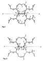
- the embodiment shown in Figure 1 is edge-side cells adjacent grid plates, the boundaries along the line A substantially - A run.
- the edge areas of adjacent grid plates consist of sub-cells 5 arranged alternately on the edge with cells 6 or 8 , the cell 6 being closed in its area bordering the cell 8 and the cell 8 being partially open and the adjoining edge areas of the cells 6 and 8 supporting elements 16 form.
- the support elements 16 consist of support walls 24 and 24 ′, as seen in horizontal section, with angled steps, with short legs 15 of the laterally open cell 8, and of angled support walls 24 of the laterally closed cell 8 .
- adjacent panels are positioned opposite each other and locked using conventional connecting elements.
- the short legs 15 of the laterally open cell 8 form-fit enclose part of the cell partition 1 of the laterally closed adjacent cell 6 .
- the sections of the support walls 24 and 24 ′ located along the edge line A - A prevent tilting about an axis of rotation parallel to the line A - A.
- the short legs 15 prevent the adjacent lattice plates from shifting laterally. Because of the relatively positive interlocking of the partial walls, pre-assembly of grids in the association from the manufacturer's factory is possible, for example, to 3 x 3 or 4 x 4 grids, without the fact that when lifting grids from transport pallets and when laying the grids, they detach from their assembly.
- Fig. 2 shows an embodiment with peripheral cells adjacent grid plates, the boundaries along the line A is also substantially - A run.
- the edge regions of the adjacent grid plates consist of sub-cells 5 arranged alternately on the edge with cells 6 or 8 , the cells 6 being closed to the region adjacent to one another and the cells 8 being open on the side, so that a cell partition 1 of a cell 8 arranged on the edge and open on the side a grid plate at its end piece 30 runs perpendicular to floor supports 61 in such a straight line that a cell partition 1 of a cell 6, which is arranged at the edge and is closed at the side, of an adjacent grid plate engages around the end piece 30 by means of slot-shaped recess 37 .
- the further configuration of the grid plate and the assembly with adjacent grid plates are provided as described for FIG. 1.
- FIG. 3 shows a modification to FIG. 2, cells 6 and cells 8 on the edge again forming support elements 16 which are designed as an extension of the cell partition construction from the cell 6 in a U-shape.
- These U-shaped configurations are slit-shaped depressions 37 arranged on the closed cell 6 via the vertical extension of the cell wall construction in the area of contact with the open cell 8 .
- In these slot-shaped depressions 37 engage the end pieces 30 of open cells 8 when joining adjacent grid plates.
- the vertical extension of the slot-shaped depressions 37 can also be limited to the upper, lower or middle vertical extension region of the edge-side cell wall construction of the closed cell 6 .
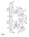
- FIG. 4 shows a further variant according to the preceding ones.
- the cell dividing wall, together with bead-like stiffening 2 with double web 4 has been omitted.
- This is in order to obtain a double-sized cell construction in the edge area of adjacent grid plates.
- Such a cell construction is provided for driving in, for example, pegs 14 or road markings, boundaries and / or parts of soil irrigation systems.
- the frame strips 62 present at right angles to the cell dividing walls 1, 1 ' in the edge region of adjacent grid plates - not shown in FIG. 4 - are interrupted. The pre-assembly, transport and laying of the grid panels are carried out as described above.
- edge-side cells 28 along an imaginary border line A - A arranged with their cell partition wall 1 or cell partition wall 1 'so that in each case the adjacent cell 28 closes off the remaining open portion of an opposing adjacent cell 28.
- the cell dividing walls 1 and 1 ' with long legs 20, 20' and short legs 15, 15 ' arranged at an angle thereon are folded axially symmetrically with respect to one another in the assembled state and are arranged to support one another.
- the short legs 15, 15 ' which touch and support each other in this way form a support element 16 in combination with the long legs 20, 20' and the end pieces 30 of the cell 28 which are located opposite each other and which are supported on them.
- This support element 16 prevents horizontal displacement of adjacent plates against each other as well as a tilting of adjacent plates to each other about an axis of rotation along the imaginary line A - A.
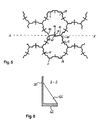
- FIG. 6 shows a detail of an edge region of the grid plate according to the invention in a top view of the underside, the basic cell structure being arranged offset by 30 ° compared to the previous exemplary embodiments.
- a floor consisting of floor supports 61 and frame strips 62 arranged on the edge of the plate, has channel-like recesses 63 on its side facing away from the cell dividing walls, which are modeled approximately on the honeycomb structure of the cells and / or sub-cells arranged above the floor.
- the upper edges of a grid plate snap into the channel-like recesses 63 of a grid plate above.
- the vertical extension outside the channel-like recesses 63 is approximately twice the material thickness of the cell dividing walls, while the depth of the channel-like recesses 63 corresponds to approximately half the vertical extension of the floor supports 61 or the frame strips 62 .
- the minimum width of the channel-like recesses 63 is selected so that it corresponds to twice the thickness of the cell partition walls.
- the base of the channel-like recesses 63 is flat.
- 3 x 3 or 4 x 4 grid plates are placed on top of one another on conventional pallets, so that the top edges of the plates below latch into the channel-like recesses 63 of plates above.
- 6 shows the area 65 outside the channel-like recesses 63 and double webs 64 .
- angle brackets 66 are shown, which in the edge region of cells for stiffening support walls 24 ' , end pieces 30' , u-, v- or slot-shaped depressions 37, cell partition walls 1, 1 ' and long legs 20, 20' are arranged.
- the angle supports 66 arranged approximately at right angles to the wall parts supporting them extend up to the frame strips 62 and thus give the wall parts of the cells arranged on the edge of particular stability.
- a corner edge piece of a grid plate is shown in plan view.
- the open cells 8 have, at their angled end pieces 30 ' , angular supports 66 which engage in the angled portion.
- Fig. 8 shows that these angle supports 66 do not quite reach the height of the wall parts, in this case the angled end piece 30 ' , and are saddled vertically in the bottom area on the frame bar 62 .
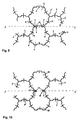
- the embodiment shown in Figure 9 shows edge-side cells adjacent grid plates, the boundaries along the line A substantially - A run.
- the edge areas of adjacent grid plates consist of sub-cells 5 arranged alternately with cells 6 or 8 , the cell 6 being closed in its area bordering the cell 8 and the cell 8 being partially open and the adjoining edge areas of the cells 6 and 8 closure elements 7 form.
- the closure elements 7 consist of V-shaped insertion slots 10 on the cell partition 1 or the bead-shaped stiffening 2 of the closed cell 6, as seen in horizontal section, and of partial walls 9 of the open cell 8 .
- adjacent panels are offset in height at the edges with their partial walls 9 positioned above the v-shaped, chamfered insertion slots 10 and at the same time all partial walls 9 of all open cells 8 of a grid plate are inserted into the v-shaped insertion slots 10 of the adjacent grid plate.
- a mounting in which the V-shaped insertion slots 10 of the adjacent grid plate to be pushed to the Operawandungen 9 is also possible, as in the immediate edge region along the line A - A no soil conditions and other connecting means are present.
- Arranged floor supports 39 are expediently provided only up to intersection points.
- Fig. 10 shows an embodiment with peripheral cells adjacent grid plates, the boundaries along the line A is also substantially - A run.
- the edge areas of the adjacent lattice panels consist of sub-cells 5 arranged alternately with cells 18 and 18 ' , the cells 18 and 18' are each open to the area adjacent to one another and partial walls 9 of the cell 18 ' with U-shaped bends 12 of the cell dividing walls open cell 18 form closure elements 17 .
- FIG. 11 shows an enlarged illustration of edge-side cells of adjacent grid plates with floor supports 39 running horizontally under the walls of cells .
- the floor supports 39 are arranged set back approximately to the height of intersections. This also has the advantage that the closure elements 7, 17, 27 can optionally be done by vertically inserting upper into lower and lower into upper cells (top and bottom each according to the arrangement in the figures) adjacent grids and also releasing connected Lattice panels is made possible.
- FIG. 12 shows a schematic section through a cell 76 of a grid plate according to the invention with indentations 78 in the form of tunnels or arches.
- the grid plate according to the invention consists of cells 76 which are open at the top and whose cell dividing walls 1 are spaced apart from the lower support 74 of the grid plate by bulges 78 which are open at the bottom.
- the cell partitions 1 are shouldered on the apex lines 75 of the convexities 78 .
- the course of the apex lines 75 of the tunnel-shaped concavities 73, 78 essentially corresponds to the course of the cell partition walls 1 arranged vertically above the concavities.
- the tunnel-shaped indentations 78 have 80 apertures 84 in its walls buckle. These serve for better root penetration and aeration, but also for material savings, in order not to unnecessarily make the grid plate according to the invention unnecessarily material-intensive without losing its strength.
- the vertical extension of the cell partition walls 1 is approximately two thirds to half of the total height of the grid plate. This results in a height of the convexities 73, 78 of approximately one third to half of the total height of the grid plate according to the invention.
- FIG. 12 and 13 show different variants of cell cross sections of the lawn grid plate, each with lower supports 74 arranged on the lower edge of the convexities 73, 78 .
- grating plates with lower supports 74 or, as shown in FIG. 15, without lower supports arranged on the lower edge of the convexities 73, 78 are offered. That is, it is intended, given the particular nature of the subsurface, that the lower edges or lower supports 74 of the bulge walls 80 press deeper into the subsurface.
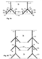
- FIG. 14 is suitable for use specifically as a grid plate for green roofing.
- the arch 73 according to the invention here contains legs 83 , which extend vertically upwards and form water chambers 82 , on the underside or lower edge of the arch walls 80 .
- FIGS. 12 to 15 The individual design variants of cell wall constructions of different types are shown in FIGS. 12 to 15, with FIGS. 12 having essentially tunnel-shaped or circular-arc-shaped cross sections of the convexities 78 , in FIGS. 14 and 15 these having a triangular shape and in FIG. 13 these have an essentially trapezoidal cross-sectional configuration.
- FIG. 15 The purpose according to the invention, namely to use the grid plate in particular as a stacking aid, is shown in FIG. 15.
- the vertical cell partition walls 1 of a grid plate are stored in the tunnel-shaped convexities 73, 78 of the next higher grid plate. Lattice panels lying one above the other can thus be stacked and transported so that they cannot slip. Since the cell partition walls 1 , which are arranged around a node, are arranged so as to engage with one another in the tunnel-shaped concavities 73, 78 of the underlying grid plate, the stacking height of several lawn grid plates is considerably reduced. At In the cell wall constructions of various lattice plates shown in FIGS. 12 to 15, the stack height is reduced by approximately one third.
- the cell partition walls 1 shouldered on the bulges 73, 78 or bulge walls 80 engage in a slip-resistant manner in the region of the apex line 75 of an overlying lattice plate.
- the dents 73, 78 do not taper at the top, but are arranged below the cell partition walls 1 in the form of penetrations of several laterally opened prismatoids with triangular, trapezoidal lateral surfaces and / or ball wedges, whereby the Taper cells 76, approximately in the shape of a truncated pyramid or a truncated cone, from the lower edge 77 of the cell dividing walls 1 .
- the aforementioned variants of cell constructions of lawn grid plates according to the invention are well suited for greening before the final laying. This is because layers of, for example, coarse mulch or planting substrates do not easily fall out of the cells 76 because of the bulges 73, 78 and lower supports 74 and fine earth can be applied to these fillings, which are then sprinkled with grass seeds and covered again with fine earth.
- the prefabricated grid panels turn green and are deeply rooted in the delicate turf. This means that they can be transported without the substrate or soil falling out of the grass pavers. Prepared or greened grid panels of this type are used where, immediately after installation, a passability is required and an overall aesthetic impression of a green area must be conveyed.
Landscapes
- Engineering & Computer Science (AREA)
- Architecture (AREA)
- Civil Engineering (AREA)
- Structural Engineering (AREA)
- Road Paving Structures (AREA)
Abstract
Description
Die Erfindung betrifft eine Gitterplatte nach dem Oberbegriff des Anspruchs 1.The invention relates to a grid plate according to the preamble of
Aus der US-Patentschrift 3 969 375 ist ein Element zur Herstellung von Spielflächen bekannt, dessen Zellen eine hexagonale Form aufweisen, wobei die am Rand des Elements gelegenen Zellen bzw. Kammern offene Teilkammern sind, die beim Aneinanderlegen von Elementen zu kompletten Zellen ergänzt werden, wobei die Zellenwände benachbarter Elemente sich nur längs ihrer vertikalen Kanten berühren.
In der EP-Schrift 0 516 957 wird eine ähnliche Gitterplatte beschrieben, die dadurch gekennzeichnet ist, daß mindestens jede übernächste randseitige Kammer geschnitten ist und durch Aneinanderlegen der vertikalen Kanten von Seitenwänden einzelner Zellen benachbarter Gitterplatten aus Teilkammern komplette Kammern bzw. Zellen gebildet werden.
Eine andere Form des Aneinanderlegens bzw. Berührens von Seitenwänden von randseitig offenen Kammern bzw. Zellen ist in dem DE-Gebrauchsmuster G 94 17 815.1 beschrieben. Die in dieser Schrift dargestellte Gitterplatte zur Befestigung von natürlichem Grund mit im Randbereich angeordneten Teilkammern weist Seitenwände auf, die beim Zusammenfügen benachbarter Platten flächig aufeinander aufliegen, wobei Abwinklungen verschiedener Formen, wie eine L-Form oder eine T-Form oder eine stumpfwinklige gegensinnige Abknickung in der Schrift bezeichnet sind.
Die DE-Schrift 44 15 595 beschreibt eine Rasengitterplatte aus Kunststoff, die an ihrer Unterseite kreis- oder polygonförmige Auflageflächen aufweist, die im wesentlichen eben sind.US Pat. No. 3,969,375 discloses an element for the production of play areas, the cells of which have a hexagonal shape, the cells or chambers located at the edge of the element being open partial chambers which are supplemented to form complete cells when elements are placed next to one another, the cell walls of adjacent elements only touching along their vertical edges.
EP-A-0 516 957 describes a similar grid plate, which is characterized in that at least every next but one chamber on the edge is cut and complete chambers or cells are formed from partial chambers by placing the vertical edges of side walls of individual cells of adjacent grid plates against one another.
Another form of contacting or touching side walls of chambers or cells open at the edge is described in DE utility model G 94 17 815.1. The grid plate shown in this document for fastening natural ground with partial chambers arranged in the edge area has side walls which lie flat on one another when adjacent plates are joined, with angled shapes of various shapes, such as an L-shape or a T-shape, or an obtuse-angled kink in of the scriptures.
DE document 44 15 595 describes a lawn grid plate made of plastic, which has circular or polygonal contact surfaces on its underside, which are essentially flat.
Die in den genannten Druckschriften beschriebenen Gitterplatten weisen eine Reihe von Nachteilen auf. Die Platten sind an ihrer Unterseite entweder vollkommen glatt und können damit nicht verrutschsicher gestapelt, geschweige denn transportiert werden, oder sie haben Dornenspitzen und sonstige Hervorhebungen, die sich besonders beim Transport in darunterliegenden Platten verhakeln und somit ebenfalls ein Hindernis für einen störungsfreien Transport darstellen.
Ein weiterer Nachteil betrifft die Gestaltung der Randzonen dieser Gitterplatten, die - wenn auch wie in dem DE-Gebrauchsmuster G 94 17 815.1 verbessert - aber immer noch nicht allen Anforderungen eines Transportierens und Verlegens von Gitterplatten auch für den individuellen Bereich genügen. Insbesondere beim leicht an- oder abgewinkelten Verlegen benachbarter Platten kommt es zum Verschieben bzw. Verrutschen dieser, weil dann beispielsweise die vertikalen Kanten von Seitenwänden einzelner Zellen benachbarter Gitterplatten oder die verschieden geformten Abwinklungen von Seitenwänden nicht, wie vorgesehen, flächig aufeinander aufliegen und sich abstützen.
Die in den genannten Druckschriften beschriebenen Gitterplatten und Elemente haben des weiteren den Nachteil eines verglichen mit dem Innenbereich dieser Platten nur schwach belastbaren Randbereichs. Dies liegt daran, daß eine gegenseitige Verriegelung zweier benachbarter Gitterplatten nur über verschiedene Befestigungs- bzw. Verriegelungsvorrichtungen im Bodenteil solcher Platten und Elemente erfolgt, wodurch sämtliche Seitenkräfte und punktuellen Druckkräfte im Randbereich von Platten bzw. Elementen nur von deren randseitigen Berührungskanten und/oder -flächen aufgenommen werden können. Bei einer sehr großen Belastung, beispielsweise beim Anfahren oder Bremsen schwerer Fahrzeuge, kann dies zu einem Bruch sowohl der im Bodenteil befindlichen Verbindungselemente als auch der nur sich längs ihrer vertikalen Kanten berührenden Seitenwände aber auch der nur flächig aufeinander aufliegenden Seitenwände benachbarter Gitterplatten führen. Ein weiterer Nachteil besteht darin, daß beim Zusammenfügen von benachbarten Platten sich Erdreich und Steine zwischen aneinanderliegende Seitenwände und zwischen die bodenseitigen Verbindungselemente schieben und die Montagearbeiten stark behindern.The grid plates described in the cited documents have a number of disadvantages. The plates are either completely smooth on their underside and therefore cannot be stacked, let alone transported, to prevent them from slipping, or they have spike tips and other accentuations that get stuck in the plates below, particularly during transport, and thus also represent an obstacle to trouble-free transport.
Another disadvantage relates to the design of the edge zones of these grid plates, which - although improved as in DE utility model G 94 17 815.1 - still do not meet all the requirements of transporting and laying grid plates for the individual area. Especially when laying adjacent panels slightly angled or angled, they move or slip, because then, for example, the vertical edges of the side walls of individual cells of adjacent grid panels or the differently shaped anglings of side walls do not lie flat on one another and are supported as intended.
The grid plates and elements described in the cited documents also have the disadvantage of an edge region which is only weakly resilient compared to the inner region of these plates. This is because a mutual locking of two adjacent grid plates only takes place via different fastening or locking devices in the base part of such plates and elements, as a result of which all lateral forces and point-like compressive forces in the edge region of plates or elements only from their edge-side contact edges and / or surfaces can be included. In the event of a very large load, for example when starting or braking heavy vehicles, this can lead to a breakage both of the connecting elements located in the base part and of the side walls which only touch along their vertical edges, but also of the side walls of adjacent grid plates which only lie flat on one another. Another disadvantage is that when neighboring plates are joined together, soil and stones slide between adjacent side walls and between the floor-side connecting elements and severely hinder the assembly work.
Es besteht daher die Aufgabe, eine Gitterplatte so weiterzubilden, daß sie insbesondere beim Transport aber auch bei einer Vormontage auf festem Grund und beim Verlegen sich nicht verschiebt. Darüber hinaus ist es Aufgabe der Erfindung, bei einfachster Gestaltung der Verbindungselemente zum Arretieren benachbarter Platten den Randbereich von Gitterplatten so zu gestalten, daß ein ungewolltes Lösen einzelner Platten aus einem Verbund mehrerer Platten während des Transports und während der Verlegearbeiten verhindert, zusätzlich der Zeitaufwand für das Verlegen von Platten erheblich gemindert wird und bei leicht welligem Gelände benachbarte Platten an ihrer Knick- bzw. Randlinie noch ausreichend sich berührend und gegen seitliches Verrutschen gesichert verlegt werden können. Außerdem ist ein Zwischenschieben von Erdreich oder Steinen zwischen die randseitigen Bodenteile benachbarter Gitterplatten bei den Verlegearbeiten zu vermeiden. Desweiteren sollen die Gitterplatten so beschaffen sein, daß sie in der Lagerhaltung und im Transport verrutschsicher zu stapeln sind.
Eine Gitterplatte ist so weiterzubilden, daß sie im Randbereich eine fast ebenso hohe Stabilität zur Aufnahme von Seitenkräften und punktuellen Druckkräften wie in ihrem Innenbereich aufweist.There is therefore the task of developing a grid plate in such a way that it does not shift, in particular during transport but also during preassembly on firm ground and when laying. In addition, it is an object of the invention to design the edge region of grid plates with the simplest design of the connecting elements for locking adjacent plates in such a way that an unwanted loosening of individual plates from a composite of several plates during transport and during the laying work prevents, in addition, the time required for this Laying slabs is significantly reduced and, in the case of slightly undulating terrain, adjacent slabs can still be touched sufficiently at their kink or edge line and secured against slipping sideways. In addition, it must be avoided that soil or stones are pushed in between the edge-side floor parts of adjacent grid plates during the laying work. Furthermore, the grid plates should be designed so that they can be stacked securely in place during storage and transport.
A grid plate is to be developed in such a way that it has almost as high stability in the edge area for absorbing lateral forces and punctual pressure forces as in its inner area.
Erfindungsgemäß wird diese Aufgabe mit den im kennzeichnenden Teil des Anspruchs 1 dargelegten Merkmalen gelöst, wobei die Merkmale der Erfindung außer aus dem Anspruch 1 auch aus den Unteransprüchen sowie aus der Beschreibung und den Zeichnungen hervorgehen, wobei die einzelnen Merkmale jeweils für sich allein oder zu mehreren in Form von Unterkombinationen der Elemente vorteilhafte, schutzfähige Ausführungen darstellen, für die mit dieser Schrift Schutz beantragt wird.According to the invention, this object is achieved with the features set out in the characterizing part of
Eine Gitterplatte zur Befestigung von Erdreich, die vorzugsweise als einstückiges Kunststoffspritzgußteil ausgebildet und mit ansetzbaren benachbarten Gitterplatten mittels Verbindungselementen verbindbar ist, weist eine Vielzahl von mit Erde verfüllbaren Zellen mit je im Boden oder zwischen Bodenauflagen angeordneten Öffnungen auf. Die aus etwa rechtwinklig zum Boden oder Bodenauflagen vertikal angeordneten Zelltrennwände bilden Zellen mit mehreckiger Querschnittsform. Erfindungsgemäß sind an Zelltrennwänden benachbarter, nicht zur selben Gitterplatte gehörender Zellen im wesentlichen vertikal verlaufende Stütz- oder Verschlußelemente angeordnet. Die Stütz- oder Verschlußelemente sind aus Teilen von Zelltrennwänden und/oder sickenförmigen Versteifungen der teilweise randseitig offenen oder geschlossenen Zellen durch ein- oder mehrfache u-, v-, trapez- und/oder stufenförmige Abwinklungen herausgebildet und/oder aus Wänden von Zellen verlängert. Im montierten Zustand zu benachbarten Gitterplatten stützen sich diese sowohl in Längs- als auch in Querverlegerichtung im montierten Zustand gegenseitig ab und sind seitlich nicht verschiebbar. Bodenauflagen und am Plattenrand angeordnete Rahmenleisten weisen an ihrer den Zelltrennwänden abgewandten Seite kanalartige Ausnehmungen oder tunnelförmige Einwölbungen auf, die etwa der Struktur, insbesondere einer wabenförmigen Struktur, der über den Bodenauflagen und den Rahmenleisten angeordneten Zellen und/oder Teilzellen nachgebildet sind. Beim Stapeln rasten die Oberkanten einer Gitterplatte in die kanalartigen Ausnehmungen oder tunnelförmigen Einwölbungen einer darüber liegenden Gitterplatte ein. Übereinanderliegende Gitterplatten sind somit verrutschsicher stapelbar und transportierbar. Da zum Übereinanderstapeln mehrerer Gitterplatten die um einen Knotenpunkt angeordneten Zelltrennwände in die tunnelförmigen Einwölbungen der darunterliegenden Gitterplatte eingreifend angeordnet sind, verringert sich die Stapelhöhe mehrerer Gitterplatten erheblich. Um dies zu erreichen, sind die Zelltrennwände auf den Scheitellinien der Einwölbungen aufgeschultert und die tunnelförmige Einwölbungen unter einem Knotenpunkt zueinander so angeordnet, daß mindestens zwei Scheitellinien, vorzugsweise drei, unterhalb des Knotenpunktes zusammentreffen. Dabei entsprechen die Scheitellinien der unter den Zelltrennwänden angeordneten tunnelförmigen Einwölbungen dem Verlauf der von den Knotenpunkten abgewinkelt verlaufenden Zelltrennwände. Um ein Verspannen gestapelter Gitterplatten zu verhindern, laufen die Einwölbungen an ihrer Oberseite nicht spitz zu, sondern sind in Form von Durchdringungen mehrerer seitlich geöffneter Prismatoiden mit dreieck-, trapezförmigen Mantelflächen, und/oder Kugelkeilen unterhalb der Zelltrennwände angeordnet, wobei sich die Zellen etwa pyramidenstumpf- oder kegelstumpfförmig ab Unterkante der Zelltrennwände nach unten verjüngen. Die vertikale Ausdehnung der Zelltrennwände beträgt etwa zwei Drittel bis die Hälfte der Gesamthöhe der Gitterplatte. Damit ergibt sich eine Höhe der Einwölbungen von etwa einem Drittel bis der Hälfte der Gesamthöhe. Die Unterkanten der Wölbungswandungen bilden untere Auflagen oder sind horizontal abgewinkelt.
Als zusätzliche Rinnen und/oder Mulden ausgebildete, vertikal nach oben abgewinkelte Wölbungswandungen dienen als Wasserspeicher.
Zur besseren Verwurzelung sind Kanäle und/oder Öffnungen in den Wölbungswänden vorgesehen.
Ein Teil der erfindungsgemäßen Stütz- oder Verschlußelemente umschließt formschlüssig einen Teil der Zelltrennwand einer benachbarten Zelle und greift arretierend in Endstücke von Zelltrennwänden. Nach dem Montieren können erfindungsgemäß vergrößerte Öffnungen entstehen, die aus zwei benachbarten, nicht zur selben Gitterplatte gehörenden, seitlich offenen Zellen gebildet sind. Fahrbahnmarkierungen, Begrenzungen und/oder Teile von Bodenbewässerungssystemen werden vorzugsweise in diesen Öffnungen angeordnet.
Ausführungsbeispiele der Erfindung sind in den Zeichnungen dargestellt und werden im folgenden näher erläutert.
In den Zeichnungen zeigen:
- Fig. 1
- Zellen benachbarter Gitterplatten mit stufenartigen Stützelementen in Draufsicht,
- Fig. 2
- Zellen benachbarter Gitterplatten mit u-förmigem Stützelement in Draufsicht,
- Fig. 3
- eine Variante nach Fig. 2,
- Fig. 4
- offene Zellen benachbarter Gitterplatten mit u-förmigen Stützelementen in Draufsicht,
- Fig. 5
- randseitige Zellen mit zwei L-förmigen Stützelementen in Draufsicht,
- Fig. 6
- Bodenauflagen einer Gitterplatte in Draufsicht von unten,
- Fig. 7
- Draufsicht auf ein Eckrandstück einer Gitterplatte mit Winkelstützen,
- Fig. 8
- Schnitt B - B nach Fig. 7, darstellend eine Winkelstütze,
- Fig. 9
- randseitige Zellen benachbarter Gitterplatten mit v-förmigem Verschlußelement in Draufsicht,
- Fig. 10
- randseitige Zellen benachbarter Gitterplatten mit u-förmigem Verschlußelement in Draufsicht,
- Fig. 11
- randseitige Zellen benachbarter Gitterplatten mit trapezförmigem Verschlußelement mit Bodenauflagen unter den Zelltrennwänden, in Draufsicht,
- Fig. 12
- schematischer Schnitt durch eine Zelle einer Gitterplatte mit bogensegmentförmigen Einwölbungen,
- Fig. 13
- schematischer Schnitt durch eine Zelle einer Gitterplatte mit trapezförmigen Einwölbungen,
- Fig. 14
- schematischer Schnitt durch eine Zelle einer Gitterplatte mit dreiecksförmigen Einwölbungen und vertikal nach oben abgewinkelten Wölbungswandungen,
- Fig. 15
- schematischer Schnitt durch Zellen von Gitterplatten in Stapelformation.
Formed as additional troughs and / or troughs, vertically angled upward arch walls serve as water reservoirs.
For better rooting, channels and / or openings are provided in the bulge walls.
Part of the support or closure elements according to the invention form-fittingly encloses part of the cell partition of an adjacent cell and engages arrestingly in end pieces of cell partitions. According to the invention, after mounting, enlarged openings can be formed which are formed from two adjacent, laterally open cells which do not belong to the same grid plate. Road markings, boundaries and / or parts of soil irrigation systems are preferably arranged in these openings.
Embodiments of the invention are shown in the drawings and are explained in more detail below.
The drawings show:
- Fig. 1
- Cells of adjacent grid plates with step-like support elements in plan view,
- Fig. 2
- Cells of adjacent grid plates with a u-shaped support element in plan view,
- Fig. 3
- 2 shows a variant according to FIG.
- Fig. 4
- top view of open cells of adjacent grid plates with u-shaped support elements,
- Fig. 5
- edge-side cells with two L-shaped support elements in plan view,
- Fig. 6
- Floor supports of a grid plate in top view from below,
- Fig. 7
- Top view of a corner edge piece of a grid plate with angle supports,
- Fig. 8
- Section B - B of FIG. 7, representing an angle bracket,
- Fig. 9
- edge-side cells of adjacent grid plates with a V-shaped closure element in plan view,
- Fig. 10
- edge-side cells of adjacent grid plates with a U-shaped closure element in plan view,
- Fig. 11
- edge-side cells of adjacent grid plates with a trapezoidal closure element with floor supports under the cell dividing walls, in plan view,
- Fig. 12
- schematic section through a cell of a grid plate with arch-segment-shaped convexities,
- Fig. 13
- schematic section through a cell of a grid plate with trapezoidal convexities,
- Fig. 14
- schematic section through a cell of a grid plate with triangular convexities and vertically angled upward convex walls,
- Fig. 15
- schematic section through cells of grid plates in stack formation.
Die erfindungsgemäße Gitterplatte dient zur Befestigung von Rasenflächen, wobei die Gitterplatte vorzugsweise als ein Kunststoffspritzgußteil hergestellt wird und durch Verbindungselemente mit weiteren Gitterplatten verlegt wird. Die Verbindungselemente können dabei wahlweise an den vertikalen Zelltrennwänden 1, 1' oder an einer Rahmenleiste 62 angeordnet sein. Durch Bodenauflagen 61 mit randseitig minimal gestalteter Fläche wird eine Behinderung beim Verbinden mehrerer Gitterplatten durch loses Erdreich bzw. Steine verringert bzw. ausgeschlossen. Die von benachbarten offenen und/oder geschlossenen Zellen 6, 8, 18, 18', 28 bzw. von Zelltrennwänden 1, 1' oder Teilen von Ihnen gebildeten Stützelemente 16 sind die zumeist formschlüssige Verbindung benachbarter Gitterplatten untereinander. Da sich der Bereich der Stützelemente 16 auf einen Teil bzw. den gesamten Bereich der Zelltrennwände 1, 1' in vertikaler Richtung ausdehnt, wird verhindert, daß beim Anheben untereinander verbundener erfindungsgemäßer Gitterplatten diese aus ihrem Verbund gelöst werden. Voraussetzung dafür ist die Verwendung von an sich bekannten Verbindungsmitteln, die, nachdem sie gegeneinander eingerastet sind, sich - sofern in einer Ebene erfolgend - nicht auf Zug und Druck in Richtung und Gegenrichtung lösen. Somit ist eine Vormontage mehrerer Gitterplatten und ein Transportieren und/oder Verlegen dieses Verbundes von mehreren Gitterplatten möglich. Verschiedenste Stützelemente 16 in Form von u-, v- und/oder L-förmigen Abwinklungen und/oder abgestuften Verlängerungen benachbarter, nicht zur selben Gitterplatte gehörender Zelltrennwände 1, 1' greifen korrespondierend ineinander bzw. umschließen Zelltrennwände 1, 1' der benachbarten Gitterplatte. Die Gestaltung aller einzelnen Elemente der erfindungsgemäßen Gitterplatte wird nachfolgend beschrieben. So auch die Gestaltung des Bodens, der Bodenauflagen 61 und der Rahmenleiste 62 sowie die Anordnung kanalartiger Ausnehmungen 63 in den Bodenauflagen 61. Die kanalartigen Ausnehmungen 63 haben erfindungsgemäß die Aufgabe zu erfüllen, beim Übereinanderlegen mehrerer Gitterplatten die Oberkanten einer darunterliegenden Gitterplatte beim Stapeln einrastend aufzunehmen, um ein seitliches Verrutschen zu verhindern und eine zusätzliche Transportsicherung zu gewährleisten.The grid plate according to the invention is used to fasten lawns, the grid plate preferably being produced as an injection molded plastic part and being laid by connecting elements with further grid plates. The connecting elements can be arranged either on the
Die in den Fig. 1 bis 15 dargestellten und nachfolgend näher zu beschreibenden Gitterplatten haben eine wabenförmige Zellengrundstruktur nach DE-OS 44 15 595, die dadurch gekennzeichnet ist, daß die Zelltrennwände 1, 1' sickenförmige Versteifungen 2 mit Stegen 3, 4 an diesen oder an den Zelltrennwänden 1, 1' aufweisen, wobei die Stege 3, 4 als Einzelstege 3 wechselseitig oder kreuzförmig als Doppelstege 4 angeordnet sind.1 to 15 and to be described in more detail below have a honeycomb cell structure according to DE-OS 44 15 595, which is characterized in that the
Die in Fig. 1 dargestellte Ausführungsform zeigt randseitige Zellen benachbarter Gitterplatten, deren Begrenzungen im wesentlichen entlang der Linie A - A verlaufen. Die Randbereiche benachbarter Gitterplatten bestehen aus randseitig mit Zellen 6 bzw. 8 alternierend angeordneten Teilzellen 5, wobei die Zelle 6 in ihrem an die Zelle 8 grenzenden Bereich geschlossen und die Zelle 8 zum Teil offen ist und die aneinandergrenzenden Randbereiche der Zellen 6 bzw. 8 Stützelemente 16 bilden. Die Stützelemente 16 bestehen aus im horizontalen Schnitt gesehen stufenartig abgewinkelten Stützwänden 24 und 24' mit kurzen Schenkeln 15 der seitlich offenen Zelle 8 sowie aus abgewinkelten Stützwänden 24 der seitlich geschlossenen Zelle 8.. The embodiment shown in Figure 1 is edge-side cells adjacent grid plates, the boundaries along the line A substantially - A run. The edge areas of adjacent grid plates consist of sub-cells 5 arranged alternately on the edge with
Zur Montage werden benachbarte Platten gegenüberliegend positioniert und mittels herkömmlicher Verbindungselemente arretiert. Dabei umschließen die kurzen Schenkel 15 der seitlich offenen Zelle 8 formschlüssig einen Teil der Zelltrennwand 1 der seitlich geschlossenen benachbarten Zelle 6. Die entlang der Randlinie A - A befindlichen Abschnitte der Stützwände 24 und 24' verhindern ein Kippen um eine Drehachse parallel zur Linie A - A. Durch die kurzen Schenkel 15 wird ein seitliches Verschieben der benachbarten Gitterplatten vermieden.
Wegen des relativ formschlüssigen Ineinanderfügens der Teilwandungen ist eine Vormontage von Gitterplatten im Verband ab Herstellerwerk beispielsweise zu 3 x 3 oder 4 x 4 Gitterplatten möglich, ohne daß beim Abheben von Gitterplatten von Transportpaletten und beim Verlegen der Gitterplatten diese sich aus ihrem Verband lösen.For assembly, adjacent panels are positioned opposite each other and locked using conventional connecting elements. The
Because of the relatively positive interlocking of the partial walls, pre-assembly of grids in the association from the manufacturer's factory is possible, for example, to 3 x 3 or 4 x 4 grids, without the fact that when lifting grids from transport pallets and when laying the grids, they detach from their assembly.
Fig. 2 zeigt eine Ausführungsform mit randseitigen Zellen benachbarter Gitterplatten, deren Begrenzungen ebenfalls im wesentlichen entlang der Linie A - A verlaufen. Die Randbereiche der benachbarten Gitterplatten bestehen aus randseitig mit Zellen 6 bzw. 8 alternierend angeordneten Teilzellen 5, wobei die Zellen 6 zum zueinander angrenzenden Bereich geschlossen und die Zellen 8 seitlich offen sind, so daß eine Zelltrennwand 1 einer am Rand angeordneten, seitlich offenen Zelle 8 einer Gitterplatte an ihrem Endstück 30 senkrecht zu Bodenauflagen 61 so geradlinig ausläuft, daß eine Zelltrennwand 1 einer am Rand angeordneten, seitlich geschlossenen Zelle 6 einer benachbarten Gitterplatte mittels schlitzförmiger Vertiefung 37 das Endstück 30 umgreift.
Die weitere Ausgestaltung der Gitterplatte und die Montage mit benachbarten Gitterplatten sind wie zu Fig. 1 beschrieben vorgesehen.Fig. 2 shows an embodiment with peripheral cells adjacent grid plates, the boundaries along the line A is also substantially - A run. The edge regions of the adjacent grid plates consist of sub-cells 5 arranged alternately on the edge with
The further configuration of the grid plate and the assembly with adjacent grid plates are provided as described for FIG. 1.
Fig. 3 zeigt eine Abwandlung zu Fig. 2, wobei wiederum randseitige Zellen 6 und Zellen 8 Stützelemente 16 bilden, die als eine Verlängerung der Zelltrennwandkonstruktion von der Zelle 6 u-förmig ausgestaltet ausgebildet sind. Diese u-förmigen Ausgestaltungen sind über die vertikale Ausdehnung der Zellenwandkonstruktion im Berührungsbereich zur offenen Zelle 8 an der geschlossenen Zelle 6 angeordnete schlitzförmige Vertiefungen 37. In diese schlitzförmigen Vertiefungen 37 greifen beim Zusammenfügen benachbarter Gitterplatten die Endstücken 30 von offenen Zellen 8 ein. Die vertikale Ausdehnung der schlitzförmigen Vertiefungen 37 kann wie in den anderen Beispielen ebenfalls auf den oberen, unteren oder mittleren vertikalen Ausdehnungsbereich der randseitigen Zellenwandkonstruktion der geschlossenen Zelle 6 begrenzt sein.FIG. 3 shows a modification to FIG. 2,
Fig. 4 stellt eine weitere Variante nach den vorangegangenen dar. Gegenüber Fig. 3 ist ersichtlich, daß zwischen den schlitzförmigen Vertiefungen 37 der geschlossenen Zelle 8 die Zelltrennwand nebst sickenförmiger Versteifung 2 mit Doppelsteg 4 weggelassen wurde. Dies deshalb, um eine doppelt große Zellkonstruktion im Randbereich benachbarter Gitterplatten zu erhalten. Eine solche Zellkonstruktion ist vorgesehen zum Einschlagen von beispielsweise Erdnägeln 14 oder Fahrbahnmarkierungen, Begrenzungen und/oder Teilen von Bodenbewässerungssystemen. Dazu werden die senkrecht zu den Zelltrennwänden 1, 1' im Randbereich benachbarter Gitterplatten vorhandenen Rahmenleisten 62 - in Fig. 4 nicht dargestellt - unterbrochen.
Die Vormontage, der Transport und das Verlegen der Gitterplatten erfolgen wie oben beschrieben.FIG. 4 shows a further variant according to the preceding ones. Compared to FIG. 3, it can be seen that between the slit-shaped
The pre-assembly, transport and laying of the grid panels are carried out as described above.
In Fig. 5 sind randseitige Zellen 28 entlang einer gedachten Randlinie A - A mit ihrer Zelltrennwand 1 oder Zelltrennwand 1' so angeordnet, daß jeweils die benachbarte Zelle 28 den noch offenen Teil einer gegenüberliegenden benachbarten Zelle 28 verschließt. Dazu sind im Berührungsbereich der benachbarten Zellen 28 die Zelltrennwände 1 bzw. 1' mit langen Schenkeln 20, 20' und daran winklig angeordneten kurzen Schenkeln 15, 15' im montierten Zustand zueinander axialsymmetrisch gegeneinander umgeklappt und sich dabei gegenseitig abstützend angeordnet. Die sich so berührenden und sich gegeneinander abstützenden kurzen Schenkel 15, 15' bilden im Verbund mit den langen Schenkeln 20, 20' und den sich an diesen abstützenden Endstücken 30 der jeweils gegenüberliegenden Zelle 28 ein Stützelement 16. Dieses Stützelement 16 verhindert sowohl ein horizontales Verschieben benachbarter Platten gegeneinander als auch ein Kippen benachbarter Platten zueinander um eine Drehachse entlang der gedachten Linie A - A.In FIG. 5 edge-
In Fig. 6 ist ein Ausschnitt eines Randbereichs erfindungsgemäßer Gitterplatte in Draufsicht auf die Unterseite dargestellt, wobei die Zellengrundstruktur gegenüber den vorhergehenden Ausführungsbeispielen um 30° versetzt angeordnet ist.
Ein Boden, bestehend aus Bodenauflagen 61 und am Plattenrand angeordneten Rahmenleisten 62 weist an seiner den Zelltrennwänden abgewandten Seite kanalartige Ausnehmungen 63 auf, die etwa der wabenförmigen Struktur der über dem Boden angeordneten Zellen und/oder Teilzellen nachgebildet sind. Beim Stapeln rasten die Oberkanten einer Gitterplatte in die kanalartigen Ausnehmungen 63 einer darüberliegenden Gitterplatte ein. Die vertikale Ausdehnung außerhalb der kanalartigen Ausnehmungen 63 beträgt etwa die doppelte Materialstärke der Zelltrennwände, während die Tiefe der kanalartigen Ausnehmungen 63 etwa der halben vertikalen Ausdehnung der Bodenauflagen 61 bzw. der Rahmenleisten 62 entspricht. Dadurch wird ein sicheres Ineinandergreifen gestapelter Gitterplatten erreicht, ein Transport auf üblichen Paletten mit einfachen Arretiermitteln wie Spannseilen und dergleichen möglich. Um ein Verklemmen der Gitterplatten beim Stapeln zu verhindern, wird die minimale Breite der kanalartigen Ausnehmungen 63 so gewählt, daß sie der doppelten Stärke der Zelltrennwände entspricht. Der Grund der kanalartigen Ausnehmungen 63 ist ebenflächig ausgebildet. Zum Stapeln werden zu 3 x 3 oder 4 x 4 Gitterplatten im Verbund auf übliche Paletten übereinandergelegt, so daß Oberkanten von untenliegenden Platten in die kanalartigen Ausnehmungen 63 darüberliegender Platten einklinken. Des weiteren sind in der Fig. 6 der Bereich 65 außerhalb der kanalarigen Ausnehmungen 63 sowie Doppelstege 64 dargestellt.FIG. 6 shows a detail of an edge region of the grid plate according to the invention in a top view of the underside, the basic cell structure being arranged offset by 30 ° compared to the previous exemplary embodiments.
A floor, consisting of floor supports 61 and frame strips 62 arranged on the edge of the plate, has channel-
In den Fig. 7 und 8 sind Winkelstützen 66 dargestellt, die im Randbereich von Zellen zur Versteifung von Stützwänden 24', Endstücken 30', u-, v- oder schlitzförmigen Vertiefungen 37, Zelltrennwänden 1, 1' und langen Schenkeln 20, 20' angeordnet sind. Je nachdem, welchem Verwendungszweck die Gitterplatten dienen sollen, erweisen sich derartige Versteifungen als sehr vorteilhaft. Die etwa im rechten Winkel zu den sie abstützenden Wandungsteilen angeordneten Winkelstützen 66 verlaufen bis auf die Rahmenleisten 62 und geben somit den Wandungsteilen der am Rand angeordneten Zellen besondere Stabilität. In Fig. 7 ist ein Eckrandstück einer Gitterplatte in Draufsicht dargestellt. Die offenen Zellen 8 weisen an ihren abgewinkelten Endstücken 30' in die Abwinklung eingreifend Winkelstützen 66 auf.7 and 8
Die Fig. 8 verdeutlicht, daß diese Winkelstützen 66 nicht ganz die Höhe der Wandungsteile, in diesem Fall das abgewinkelte Endstück 30', erreichen und im Bodenbereich auf der Rahmenleiste 62 senkrecht aufgesattelt sind.Fig. 8 shows that these angle supports 66 do not quite reach the height of the wall parts, in this case the angled end piece 30 ' , and are saddled vertically in the bottom area on the
Die in Fig. 9 dargestellte Ausführungsform zeigt randseitige Zellen benachbarter Gitterplatten, deren Begrenzungen im wesentlichen entlang der Linie A - A verlaufen. Die Randbereiche benachbarter Gitterplatten bestehen aus randseitig alternierend mit Zellen 6 bzw. 8 angeordneten Teilzellen 5, wobei die Zelle 6 in ihrem an die Zelle 8 grenzenden Bereich geschlossen und die Zelle 8 zum Teil offen ist und die aneinandergrenzenden Randbereiche der Zellen 6 bzw. 8 Verschlußelemente 7 bilden. Die Verschlußelemente 7 bestehen aus im horizontalen Schnitt gesehen v-förmigen Einschubschlitzen 10 an der Zelltrennwand 1 bzw. der sickenförmigen Versteifung 2 der geschlossenen Zelle 6 sowie aus Teilwandungen 9 der offenen Zelle 8.
Zur Montage werden benachbarte Platten höhenversetzt randseitig mit ihren Teilwandungen 9 über den v-förmigen, angefasten Einschubschlitzen 10 positioniert und zugleich alle Teilwandungen 9 aller offenen Zellen 8 einer Gitterplatte in die v-förmigen Einschubschlitze 10 der benachbarten Gitterplatte eingeschoben. Eine Montage, bei der die v-förmigen Einschubschlitze 10 auf die Teilwandungen 9 der benachbarten Gitterplatte geschoben werden, ist ebenfalls möglich, da in dem unmittelbaren Randbereich entlang der Linie A - A keine Bodenauflagen und sonstigen Verbindungsmittel vorhanden sind.
Für eine Montage, die wahlweise ein Aufeinanderschieben von Zellen 8 auf 6 oder Zellen 6 auf 8 vorsieht, sind die unterhalb der Zelltrennwände 1, 1' - nur in der Figur 11 dargestellten - angeordneten Bodenauflagen 39 zweckmäßigerweise nur bis zu Schnittpunkten vorgesehen.
Durch die auf die Schnittpunkte 11 zurückversetzten Bodenauflagen wird beim Aneinanderkoppeln weiterer Einzelplatten oder eines Plattenverbandes verhindert, daß Erdreich oder Steine ein Zusammenstecken der Gitterplatten behindern. Leichte noppenförmige Erhebungen entlang der Einschub- und vertikalen Gleitflächen der v-förmigen Einschubschlitze 10, der u-förmigen Abwinklungen 12, der trapezförmigen Verlängerungen 13 und/oder entlang der Teilwandungen 9 erhöhen das Festineinandergreifen bzw. Verriegeln der Verschlußelemente 7, 17, 27.. The embodiment shown in Figure 9 shows edge-side cells adjacent grid plates, the boundaries along the line A substantially - A run. The edge areas of adjacent grid plates consist of sub-cells 5 arranged alternately with
For assembly, adjacent panels are offset in height at the edges with their
For an assembly which optionally provides for
Due to the floor supports set back to the intersection points 11 , when coupling further individual plates or a plate assembly together, it is prevented that soil or stones hinder the grid plates from being plugged together. Slight nub-shaped elevations along the insertion and vertical sliding surfaces of the v-shaped
Fig. 10 zeigt eine Ausführungsform mit randseitigen Zellen benachbarter Gitterplatten, deren Begrenzungen ebenfalls im wesentlichen entlang der Linie A - A verlaufen. Die Randbereiche der benachbarten Gitterplatten bestehen aus randseitig alternierend mit Zellen 18 bzw. 18' angeordneten Teilzellen 5, wobei die Zellen 18 und 18' zum zueinander angrenzenden Bereich jeweils offen sind und Teilwandungen 9 der Zelle 18' mit u-förmigen Abwinklungen 12 der Zelltrennwände der offenen Zelle 18 Verschlußelemente 17 bilden.Fig. 10 shows an embodiment with peripheral cells adjacent grid plates, the boundaries along the line A is also substantially - A run. The edge areas of the adjacent lattice panels consist of sub-cells 5 arranged alternately with
Fig. 11 zeigt eine vergrößerte Darstellung randseitiger Zellen benachbarter Gitterplatten mit horizontal unter den Wänden von Zellen verlaufenden Bodenauflagen 39. Zum Zwecke der Vermeidung des Zwischenschiebens von Erdreich und Steinen zwischen bei herkömmlichen Gitterplatten im unteren Bereich vorhandene Bodenränder und/oder Verbindungsmittel, überlappende Bodenauflagen und dergleichen werden erfindungsgemäß die Bodenauflagen 39 etwa auf die Höhe von Schnittpunkten zurückversetzt angeordnet. Dies bringt außerdem noch den Vorteil, daß die Verschlußelemente 7, 17, 27 wahlweise durch vertikales Einschieben von oberen in untere und unteren in obere Zellen (oben und unten jeweils nach Anordnung in den Fig. bezeichnet) benachbarter Gitterplatten erfolgen kann und ebenfalls ein Lösen verbundener Gitterplatten so ermöglicht wird.11 shows an enlarged illustration of edge-side cells of adjacent grid plates with floor supports 39 running horizontally under the walls of cells . For the purpose of avoiding the pushing in of soil and stones between the bottom edges and / or connecting means present in the lower region of conventional grid plates and / or connecting means, overlapping floor coverings and the like According to the invention, the floor supports 39 are arranged set back approximately to the height of intersections. This also has the advantage that the
Eine Kombination von zurückversetzten Bodenauflagen 39 mit einigen am Plattenrand A - A angeordneten Randstücken etwa in Form von Bodenauflagen 39 liegt im Bereich der Erfindung.
Zum Ausgleich von Bodenunebenheiten aber auch zum Verlegen von Gitterplatten an Böschungen liegt es im Bereich der Erfindung, die Verschlußelemente 7, 17, 27 wahlweise nur im oberen oder nur im unteren oder nur im mittleren Bereich der vertikalen Ausdehnung von randseitigen Wänden von Zellen benachbarter Gitterplatten anzuordnen. Mit einer derartigen Anordnung sind Geländeunebenheiten und kleine Böschungen von etwa 10° bis 15° problemlos ausgleichbar, insbesondere auch dann, wenn die Verschlußelemente 7, 17, 27 leicht bogenförmig bzw. leicht spitzwinklig an den Wänden der Zellen angeordnet sind.A combination of recessed floor supports 39 with some edge pieces arranged on the plate edge A - A , for example in the form of floor supports 39, is within the scope of the invention.
To compensate for unevenness in the floor, but also for laying grid plates on embankments, it is within the scope of the invention to arrange the
Fig. 12 zeigt einen schematischen Schnitt durch eine Zelle 76 einer erfindungsgemäßen Gitterplatte mit tunnel- bzw. bogensegmentförmigen Einwölbungen 78. Die erfindungsgemäße Gitterplatte besteht aus nach oben offenen Zellen 76, deren Zelltrennwände 1 durch nach unten offene Einwölbungen 78 zur unteren Auflage 74 der Gitterplatte beabstandet angeordnet sind. Die Zelltrennwände 1 sind auf den Scheitellinien 75 der Einwölbungen 78 aufgeschultert. Der Verlauf der Scheitellinien 75 der tunnelförmigen Einwölbungen 73, 78 entspricht im wesentlichen dem Verlauf der über den Einwölbungen senkrecht angeordneten Zelltrennwände 1. Dabei ist es für die Funktion der Einwölbungen 73, 78 unerheblich, ob Zelltrennwände 1 und Scheitellinien 75 vollständig oder nur im Bereich von Knotenpunkten bis zur ersten Abwinklung der Zelltrennwände 1 deckungsgleich verlaufen.
Die tunnelförmigen Einwölbungen 78 weisen in ihren Wölbungswänden 80 Öffnungen 84 auf. Diese dienen der besseren Durchwurzelung und Durchlüftung, aber auch der Materialersparnis, um die erfindungsgemäße Gitterplatte nicht unnötigerweise materialintensiv zu gestalten, ohne daß sie dabei an Festigkeit verliert.
Die vertikale Ausdehnung der Zelltrennwände 1 beträgt etwa zwei Drittel bis zur Hälfte der Gesamthöhe der Gitterplatte. Damit ergibt sich eine Höhe der Einwölbungen 73, 78 von etwa einem Drittel bis zur Hälfte der Gesamthöhe der erfindungsgemäßen Gitterplatte.FIG. 12 shows a schematic section through a
The tunnel-shaped
The vertical extension of the
In den Fig. 12 und 13 sind verschiedene Varianten von Zellquerschnitten der Rasengitterplatte dargestellt, jeweils mit an der Unterkante der Einwölbungen 73, 78 angeordneten unteren Auflagen 74. Je nach Verwendungszweck, insbesondere beabsichtigter Belastbarkeit sowie Beschaffenheit des Untergrundes, auf dem erfindungsgemäße Gitterplatten verlegt werden sollen, werden Gitterplatten mit unteren Auflagen 74 oder - wie in Fig. 15 dargestellt - ohne an der Unterkante der Einwölbungen 73, 78 angeordnete untere Auflagen angeboten. Das heißt, es ist bei besonderer Beschaffenheit des Untergrundes beabsichtigt, daß sich die Unterkanten bzw. unteren Auflagen 74 der Wölbungswände 80 tiefer in den Untergrund eindrücken. Somit bilden sich im oberen Bereich der Einwölbungen 73, 78 kleine Luftpolster, die insbesondere in der Anwachsphase der guten Bodendurchlüftung als auch der Wasserbevorratung dienlich sind. Für die Verwendung speziell als Gitterplatte zur Dachbegrünung ist die in Fig. 14 dargestellte Zellkonstruktion geeignet. Die erfindungsgemäße Einwölbung 73 enthält hier an der Unterseite bzw. unteren Kante der Wölbungswände 80 senkrecht nach oben reichende Schenkel 83, die Wasserkammern 82 bilden.
Die einzelnen Ausführungsvarianten verschiedenartig gestalteter Zellwandkonstruktionen sind in den Fig. 12 bis 15 dargestellt, wobei die Fig. 12 im wesentlichen tunnel- bzw. kreisbogensegmentförmige Querschnitte der Einwölbungen 78 aufweisen, in den Fig. 14 und 15 diese eine Dreieckform und in der Fig. 13 diese eine im wesentlichen trapezförmige Querschnittsgestaltung aufweisen.12 and 13 show different variants of cell cross sections of the lawn grid plate, each with
The individual design variants of cell wall constructions of different types are shown in FIGS. 12 to 15, with FIGS. 12 having essentially tunnel-shaped or circular-arc-shaped cross sections of the
Erfindungsgemäßer Zweck, nämlich die Gitterplatte insbesondere als Stapelhilfe zu verwenden, ist in der Fig. 15 dargestellt. Beim Stapeln erfindungsgemäßer Gitterplatten sind die vertikalen Zelltrennwände 1 einer Gitterplatte in den tunnelförmigen Einwölbungen 73, 78 der nächsthöheren Gitterplatte gelagert. Übereinanderliegende Gitterplatten sind somit verrutschsicher stapelbar und transportierbar. Da zum Übereinanderstapeln mehrerer Gitterplatten die um einen Knotenpunkt angeordneten Zelltrennwände 1 in die tunnelförmigen Einwölbungen 73, 78 der darunterliegenden Gitterplatte eingreifend angeordnet sind, verringert sich die Stapelhöhe mehrerer Rasengitterplatten erheblich. Bei den in den Fig. 12 bis 15 dargestellten Zellwandkonstruktionen verschiedener Gitterplatten verringert sich die Stapelhöhe um etwa ein Drittel. Wie aus der Fig. 15 ersichtlich, greifen die auf den Einwölbungen 73, 78 bzw. Wölbungswänden 80 aufgeschulterte Zelltrennwände 1 im Bereich der Scheitellinie 75 einer darüberliegenden Gitterplatte verrutschsicher ein. Um ein Verspannen gestapelter Rasengitterplatten zu verhindern, laufen die Einwölbungen 73, 78 an ihrer Oberseite nicht spitz zu, sondern sind in Form von Durchdringungen mehrerer seitlich geöffneter Prismatoiden mit Dreieck-, trapezförmigen Mantelflächen und/oder Kugelkeilen unterhalb der Zelltrennwände 1 angeordnet, wobei sich die Zellen 76 etwa pyramidenstumpf- oder kegelstumpfförmig ab Unterkante 77 der Zelltrennwände 1 nach unten verjüngen.The purpose according to the invention, namely to use the grid plate in particular as a stacking aid, is shown in FIG. 15. When stacking grid plates according to the invention, the vertical
Die vorbezeichneten Varianten von Zellkonstruktionen erfindungsgemäßer Rasengitterplatten eignen sich wegen ihrer besonderen Konstruktion im unteren Bereich der Zellen 76 gut für eine Begrünung bereits vor dem endgültigen Verlegen. Dies deshalb, weil Schichten von beispielsweise grobem Mulch- oder Pflanzsubstrat wegen der Einwölbungen 73, 78 und unteren Auflagen 74 nicht ohne weiteres aus den Zellen 76 herausfallen und auf diesen Auffühllungen Feinerde aufbringbar ist, die sodann mit Grassamen bestreut und nochmals mit Feinerde abgedeckt wird. Die so vorgefertigten Gitterplatten begrünen sich und werden von der zarten Grasnarbe stark durchwurzelt. Damit sind sie transportfähig, ohne daß Substrat bzw. Erdreich aus den Rasengitterplatten herausfällt. Derartig vorbereitete bzw. begrünte Gitterplatten finden dort Verwendung, wo sofort nach Verlegen sowohl eine Befahrbarkeit erforderlich ist und ein ästhetischer Gesamteindruck einer begrünten Fläche vermittelt werden muß.Because of their special construction in the lower area of the
In der vorliegenden Erfindung wurde anhand konkreter Ausführungsbeispiele eine Gitterplatte mit Stütz- und Verschlußelementen zu benachbarten Gitterplatten erläutert. Es sei aber vermerkt, daß die vorliegende Erfindung nicht auf die Einzelheiten der Beschreibung in den Ausführungsbeispielen eingeschränkt ist, da im Rahmen der Patentansprüche Änderungen und Abwandlungen beansprucht werden. Kombinationen von mehreren solcher Stützelemente 16 und Verschlußelemente 7, 17, 27 sind möglich, wobei Anordnung, Art und Anzahl von der erforderlichen und gewünschten Stabilität und Festigkeit der einzelnen Platten bestimmt wird. Durch geeignete Ausformungen, insbesondere vertikal bogenförmig gestaltete Abwinklungen ist ein Verlegen erfindungsgemäßer Gitterplatten auch an Neigungen des Untergrundes anpaßbar. Auch liegt es im Bereich der Erfindung, die Stützelemente 16 oder Verschlußelemente 7, 17, 27 nicht über die ganze vertikale Ausdehnung der randseitigen Zelltrennwände 1, 1' auszudehnen, sondern diese nur im oberen, unteren oder mittleren vertikalen Berührungsbereich benachbarter Zellen anzuordnen.In the present invention, a grid plate with support and closure elements for neighboring grid plates has been explained using specific exemplary embodiments. However, it should be noted that the present invention is not restricted to the details of the description in the exemplary embodiments, since changes and modifications are claimed within the scope of the patent claims. Combinations of several
Claims (19)
Applications Claiming Priority (6)
| Application Number | Priority Date | Filing Date | Title |
|---|---|---|---|
| DE19616237 | 1996-04-15 | ||
| DE1996116237 DE19616237A1 (en) | 1996-04-15 | 1996-04-15 | Modular grating laid on earth or grass |
| DE19616235 | 1996-04-15 | ||
| DE1996116233 DE19616233A1 (en) | 1996-04-15 | 1996-04-15 | Lattice panel for stabilising soil |
| DE19616233 | 1996-04-15 | ||
| DE1996116235 DE19616235A1 (en) | 1996-04-15 | 1996-04-15 | Grating or ground reinforcement plate |
Publications (2)
| Publication Number | Publication Date |
|---|---|
| EP0802283A2 true EP0802283A2 (en) | 1997-10-22 |
| EP0802283A3 EP0802283A3 (en) | 1998-05-13 |
Family
ID=27216173
Family Applications (1)
| Application Number | Title | Priority Date | Filing Date |
|---|---|---|---|
| EP97250118A Withdrawn EP0802283A3 (en) | 1996-04-15 | 1997-04-15 | Grating |
Country Status (1)
| Country | Link |
|---|---|
| EP (1) | EP0802283A3 (en) |
Cited By (3)
| Publication number | Priority date | Publication date | Assignee | Title |
|---|---|---|---|---|
| WO2006100705A1 (en) * | 2005-03-23 | 2006-09-28 | Claudioforesi S.R.L. | Modular grid used to obtain carriageable pavements on grass or sand surfaces |
| EP1840266A1 (en) * | 2006-03-28 | 2007-10-03 | Sell Kunststoffen B.V. | Plate-shaped construction element |
| EP2116648A1 (en) * | 2008-05-09 | 2009-11-11 | Christian Peneder | Plantable grid body for holding traffic loads |
Family Cites Families (4)
| Publication number | Priority date | Publication date | Assignee | Title |
|---|---|---|---|---|
| DE9216549U1 (en) * | 1992-12-04 | 1994-04-07 | Prestele, Eugen, 86161 Augsburg | Grid plate |
| DE9421260U1 (en) * | 1994-02-18 | 1995-07-27 | Eberhard, Alf Hans, 78465 Konstanz | Component for the production of surfaces with a hexagonal layout of the same side length |
| DE4415595A1 (en) * | 1994-04-28 | 1995-11-02 | Dieter Chaloun | Paving stone for laying on grass |
| DE9417815U1 (en) * | 1994-11-07 | 1995-01-05 | Kienle, Alexander, 86152 Augsburg | Grid plate for fixing natural ground |
-
1997
- 1997-04-15 EP EP97250118A patent/EP0802283A3/en not_active Withdrawn
Cited By (3)
| Publication number | Priority date | Publication date | Assignee | Title |
|---|---|---|---|---|
| WO2006100705A1 (en) * | 2005-03-23 | 2006-09-28 | Claudioforesi S.R.L. | Modular grid used to obtain carriageable pavements on grass or sand surfaces |
| EP1840266A1 (en) * | 2006-03-28 | 2007-10-03 | Sell Kunststoffen B.V. | Plate-shaped construction element |
| EP2116648A1 (en) * | 2008-05-09 | 2009-11-11 | Christian Peneder | Plantable grid body for holding traffic loads |
Also Published As
| Publication number | Publication date |
|---|---|
| EP0802283A3 (en) | 1998-05-13 |
Similar Documents
| Publication | Publication Date | Title |
|---|---|---|
| DE2704722C2 (en) | Plant container | |
| EP0516957B1 (en) | Grating | |
| EP0430890B1 (en) | Wall element for dry construction of walls, building system for securing slopes and slope wall built with the building system | |
| DE2731228C2 (en) | Concrete shaped stone for the production of a retaining wall and retaining wall made of such shaped stones | |
| DE69628182T2 (en) | CELL-shaped LIMIT STRUCTURE | |
| EP0319465A1 (en) | Set of concrete wall stones for constructing a day-stacked wall | |
| EP0455260B1 (en) | Support element for grass surfacings | |
| DE3320744A1 (en) | ROOF TILE | |
| AT399007B (en) | WATER STORAGE PLATE | |
| EP0187615B1 (en) | Set of elements for composite constructions | |
| EP0039448A2 (en) | Wall made of concrete elements | |
| DE10062711C2 (en) | Plastic grid plate for fastening street banquets | |
| EP0802283A2 (en) | Grating | |
| EP0024500B1 (en) | Concrete building element | |
| WO1992020864A1 (en) | Flat moulded concrete slab for ground coverage | |
| DE4415595A1 (en) | Paving stone for laying on grass | |
| EP0679764B1 (en) | Grating for grass surfacing and grass surface stabilisation with gratings | |
| DE4014935C2 (en) | ||
| CH686296A5 (en) | Rasenschutzwabe. | |
| DE19616235A1 (en) | Grating or ground reinforcement plate | |
| DE29602675U1 (en) | Shaped stone for surface fastening of floor surfaces | |
| DE19640819A1 (en) | Rectangular cell for forming fixed lawn surface, etc. | |
| DE2737322A1 (en) | Ornamental brick for garden wall - comprises two arms forming lattice with adjacent similar bricks and corrugated to fit together | |
| DE102016115212A1 (en) | Load distribution plate made of plastic | |
| EP0860550A2 (en) | Device for planting trees |
Legal Events
| Date | Code | Title | Description |
|---|---|---|---|
| PUAI | Public reference made under article 153(3) epc to a published international application that has entered the european phase |
Free format text: ORIGINAL CODE: 0009012 |
|
| AK | Designated contracting states |
Kind code of ref document: A2 Designated state(s): AT BE CH DK ES FR GB IE IT LI NL |
|
| PUAL | Search report despatched |
Free format text: ORIGINAL CODE: 0009013 |
|
| AK | Designated contracting states |
Kind code of ref document: A3 Designated state(s): AT BE CH DK ES FR GB IE IT LI NL |
|
| 17P | Request for examination filed |
Effective date: 19980918 |
|
| RAP3 | Party data changed (applicant data changed or rights of an application transferred) |
Owner name: HORTI-PLAST GMBH |
|
| RAP1 | Party data changed (applicant data changed or rights of an application transferred) |
Owner name: SCHWILL, HANS-DIETER |
|
| 17Q | First examination report despatched |
Effective date: 20001208 |
|
| GRAH | Despatch of communication of intention to grant a patent |
Free format text: ORIGINAL CODE: EPIDOS IGRA |
|
| STAA | Information on the status of an ep patent application or granted ep patent |
Free format text: STATUS: THE APPLICATION HAS BEEN WITHDRAWN |
|
| 18W | Application withdrawn |
Effective date: 20030405 |