EP0802094A2 - Réglage en hauteur d'un renvoi de ceinture de sécurité - Google Patents
Réglage en hauteur d'un renvoi de ceinture de sécurité Download PDFInfo
- Publication number
- EP0802094A2 EP0802094A2 EP97106590A EP97106590A EP0802094A2 EP 0802094 A2 EP0802094 A2 EP 0802094A2 EP 97106590 A EP97106590 A EP 97106590A EP 97106590 A EP97106590 A EP 97106590A EP 0802094 A2 EP0802094 A2 EP 0802094A2
- Authority
- EP
- European Patent Office
- Prior art keywords
- pawl
- rail
- deflection
- bowden cable
- bearing
- Prior art date
- Legal status (The legal status is an assumption and is not a legal conclusion. Google has not performed a legal analysis and makes no representation as to the accuracy of the status listed.)
- Granted
Links
Images


Classifications
-
- B—PERFORMING OPERATIONS; TRANSPORTING
- B60—VEHICLES IN GENERAL
- B60R—VEHICLES, VEHICLE FITTINGS, OR VEHICLE PARTS, NOT OTHERWISE PROVIDED FOR
- B60R22/00—Safety belts or body harnesses in vehicles
- B60R22/18—Anchoring devices
- B60R22/20—Anchoring devices adjustable in position, e.g. in height
- B60R22/201—Anchoring devices adjustable in position, e.g. in height with the belt anchor connected to a slider movable in a vehicle-mounted track
- B60R22/205—Anchoring devices adjustable in position, e.g. in height with the belt anchor connected to a slider movable in a vehicle-mounted track the slider comprising emergency actuated locking means
Definitions
- the present invention relates to a device for automatically height-adjustable mounting of the upper fastening or deflection fitting for a seat belt in a vehicle, with a substantially vertically arranged rail, which has lateral snap-in receptacles, with a slider guided along the rail, in which a pawl with a laterally projecting latch between a latching position and a latching position is pivotally mounted about an axis perpendicular to the longitudinal direction of the rail, with an adjusting element acting on the pawl in one direction of displacement, controlled as a function of the seat position of the assigned vehicle seat, and with a bearing movable for the slide member for the deflection fitting, which engages on the pawl in such a way that the pawl is pivoted into its latching position when the bearing is loaded by the belt.
- Such a device is known for example from DE 38 02 323 C2.
- the pawl is pivotally mounted in the slider about a pivot point predetermined by the slider.
- the adjusting element engages the pawl in one pivoting direction, while the pawl is supported on the other side of the pivot point on a restoring element acting in the opposite pivoting direction. This ensures that when the slide is moved along the rail without loading the bearing for the deflection fitting, the pawl remains in its disengaged position.
- the bearing for the deflection fitting is firmly connected to the slider in this known device.
- the slide with the pivot point in the rail is therefore moved downward, while the pawl is held on one side of the pivot point by the adjusting element defined by the seat position.
- the pawl pivots and snaps into one of the side snap-in receptacles of the rail, so that the slider with the bearing for the deflection fitting is blocked against further displacement along the rail.
- the present invention is therefore based on the object of developing a device of the type mentioned in such a way that these disadvantages do not occur.
- the structure should be simplified in spite of ensuring a safe displacement of the slider in both directions, in order to reduce the manufacturing costs and to increase the functional reliability.
- This object is achieved in that a restoring element acting on the pawl in the other direction of displacement is provided, and in that the adjusting element and engage the return element on the pawl at two points arranged on the same side of the pivot axis.
- the arrangement of the return element and the adjusting element in such a way that they engage the pawl in the opposite direction at points arranged on the same side of the pivot axis ensures that no actuating torque acts on the pawl, that is to say the pawl during the Displacement of the slider without loading the bearing for the deflection fitting remains in its disengaged position.
- the reset element provided according to the invention thus has a double function.
- the restoring element transmits a displacement force which counteracts the adjusting element and, on the other hand, the restoring element prevents the pawl from snapping into place during the adjustment of the device, that is to say when the bearing is not loaded.
- a separate reset element preventing the engagement can therefore be dispensed with. This gives a function which is improved in function but is simple in construction, which is characterized by reduced production costs and increased durability, since there are fewer parts which are subject to wear or may fail.
- the bearing for the deflection fitting is arranged on the pawl, the arrangement being horizontally offset from the point of engagement of the adjusting element.
- This offset arrangement has the effect that, when the bearing for the deflection fitting is loaded, the pawl is pivoted into its latching position relative to the slider, because the pulling movement transmitted from the belt to the bearing counteracts the adjustment element defined by the sitting position.
- the force absorbed by the bearing is transmitted directly to the pawl, so that the slider is not designed for this high force have to be.
- a pivot bearing is not even required per se on the slide, although such is provided according to a preferred embodiment of the invention.
- the bearing arranged on the pawl is provided for the deflection fitting on the axis of rotation of the pawl in the slider.
- a force transmitted from the belt to the bearing for the deflection fitting therefore acts vertically downwards on the pivot bearing axis and tries to move the pawl downwards along the rail. Due to the adjusting element which acts on the pawl and is displaced relative to the bearing of the deflecting fitting, this results in a resulting torque which leads to pivoting of the pawl and its latching into the lateral latching receptacles of the rail.
- the pawl has a passage through which a longitudinally stepped pin with its narrower section, which is designed as a bearing for the deflection fitting, is passed, the wider section of the pin being designed as a pivot bearing pin which is located in a corresponding circular recess in the Slider is rotatably mounted.
- the stepped configuration of the pin has the advantage that the pin cannot be pulled out of the pawl when the deflection fitting is loaded by the belt.
- the stepped pin with its narrower section is preferably inserted with a press fit into the pawl.
- the pawl is mounted in a two-part housing, the lower housing part of which serves as a slider and the upper housing part together with the pawl can be pivoted relative to the lower housing part in the rail plane, the adjusting element and the restoring element acting on the upper housing part.
- This configuration enables the adjustment element and the restoring element to be easily attached to the upper housing part, which can be made in particular of plastic, and at the same time the pawl is made from a particularly stable material, in particular metal.
- a rope, in particular a Bowden cable, is preferably used as the adjusting element for displacing the slider along the rail.
- the Bowden cable is preferably guided over a deflection device and acts from above on the pawl or on the upper housing part.
- the other end of the Bowden cable is moved when moving the vehicle seat in such a way that the Bowden cable is most extended in the foremost seating position, so that the deflection fitting is in its lowest position.
- the Bowden cable pulls the deflection fitting into its uppermost position when the vehicle seat is in its rearmost position.
- the restoring element acts accordingly on the lower end of the pawl or of the upper housing part, which therefore prestresses the deflection fitting into its lowest position. When the Bowden cable is extended, this ensures that the deflection fitting is moved downward into the desired position.
- a spiral spring is provided as the restoring element, the spiral spring preferably being mounted in a spring sleeve which can be anchored in the rail and which has a central passage for a fastening bolt.
- the spring sleeve thus also serves to mount the spiral spring and to fasten the rail to the vehicle.
- the spring sleeve can also be provided with a lateral receptacle for the end of the jacket of the Bowden cable, so that the spring sleeve takes on a further function. This multi-purpose function of the spring sleeve further reduces the manufacturing and assembly costs.
- a spreading spring element is provided on the pawl, which is held in an unexpanded position by the tensioning force acting between the adjusting element and the restoring element, the spreading spring element being arranged between the pawl and slide piece or between the pawl and rail such that the pawl is eliminated the clamping force is loaded by the expansion spring element in the direction of its latching position.
- the spreading spring element advantageously ensures that the pawl securely engages even in the event of a defect in the adjusting element or the restoring element or a part connected to it, for example when the Bowden cable breaks or unhooks, and blocks the slide with the bearing for the deflection fitting against vertical displacement becomes. In the event of a defect in the adjusting element, the clamping force ceases to exist, so that the spreading spring element spreads out and the pawl is pivoted into its latched position.
- the spreading spring element is preferably designed as a bracket with two resilient legs, which is supported in the spread state with its one leg on the pawl and with its other leg on the slider, the span of the bracket being variable as a function of the tensioning force. If the clamping force is present, the two legs of the bracket are pivoted together so far that the bracket does not exert any pivoting force on the latch. Falls the tension away, the bracket spreads and loads the pawl in the locking direction.
- the pawl has a contact edge at least for each part of the two legs of the bracket and the bracket is held against the contact edge by the clamping force so that the two legs are pivoted together so far that the pawl of the bracket is relieved.
- the contact edge can preferably be formed by a recess in the area of the point of attack of the adjusting element, and the adjusting element can preferably engage at the connection point of the two legs of the bracket and pull it against the contact edge.
- the distance of the deflection device for the Bowden cable from the upper end of the rail is manually adjustable. With each length of the Bowden cable set via the seating position, the height of the deflection fitting thus predetermined can thus be additionally changed over a certain range. This can take into account the fact that the seating position chosen by a person does not always correlate completely with their body size or shoulder height.
- the deflection device has a lever element which is rotatably mounted about an essentially horizontal axis and which carries a deflection element for the Bowden cable and an actuating element, the deflection element being arranged closer to the axis of rotation of the lever element than that Actuator.
- the force required for manual adjustment is advantageously kept low. This is particularly important because when the deflection element is adjusted manually, the height-adjustable deflection fitting covers twice the distance as the actuating element.
- a deflection roller is preferably provided to deflect the Bowden cable.
- the friction which occurs when the Bowden cable is actuated is thereby reduced, which on the one hand increases the functional reliability of the device and on the other hand facilitates an additional manual height adjustment.
- the device according to the invention is suitable for use on both sides in a motor vehicle. All parts of the device according to the invention with the exception of the upper housing part can then be used for both left and right-hand installation.
- the rail is preferably provided with slots for hanging in a receptacle on the vehicle.
- the assembly of the device according to the invention is considerably facilitated.
- the rail is suspended from below into the receptacle, for example on the B-pillar of the vehicle, and then only has to be fastened to the B-pillar by means of the single fastening bolt guided through the spring sleeve.
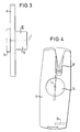
- the height adjustment device according to the invention for the deflection fitting of a seat belt shown in FIG. 1 comprises a rail 1 to be attached vertically, for example to the B-pillar of a motor vehicle, which rail has two lateral legs 2 with a C-shaped cross section, which are connected to one another on the rear side of the rail via a rear wall 3 are connected.
- locking receptacles 4 are provided, for example, as shown can be produced by expressing corresponding sections 5 of the side legs 2.
- a two-part housing 6 is inserted, the lower housing part 7 of which is displaceably guided along the rail 1.
- the housing 6 accommodates a pawl 8 which, together with the upper housing part 9, can be rotated relative to the lower housing part 7 about a central axis I.
- the pawl 8 is provided with recesses 26 into which corresponding projections, not shown here, provided in the upper housing part 9 engage.
- One of the two recesses 26 and the associated projection can be offset with respect to the central axis I in order to prevent incorrect assembly by turning the pawl 8 and upper housing part by 180 ° relative to one another.
- the pawl 8 has a laterally projecting nose 10 and a central bushing 11, in which, as can be seen in FIG. 3, a stepped pin 12 with its narrower section 13 with an interference fit is inserted.
- the narrower section 13 is designed as a threaded bushing which is guided through a central passage 14 in the upper housing part 9 and serves as a bearing for a corresponding threaded bolt of a deflection fitting, not shown here.
- the wider section 15 of the stepped pin 12 has a diameter which is adapted to the diameter of a recess 16 in the lower housing part 7, so that the wider section 15 of the stepped pin 12 with the recess 16 in the lower housing part as a rotary bearing for the pawl 8 and that Upper housing part 9 interacts.
- the upper housing part 9 has a receptacle 17 for the end in its section located above the bushing 14 18 of a Bowden cable 19, which is guided from above to the upper housing part 9 via a deflection device 20.
- the end 18 of the Bowden cable 19 is provided with a thickening 21 which engages behind an associated edge in the receptacle 17 in the upper housing part 9.
- the receptacle 17 for the Bowden cable 19 is arranged horizontally offset with respect to the central axis I, about which the upper housing part 9 can be rotated.
- the end 22 of a spiral spring 23 engages in a recess 24 provided in the lower section of the upper housing part 9 and is anchored at its other end in a spring receptacle 25.
- the spring holder 25 is in turn inserted into the lower end of the rail 1 and anchored to it.
- the deflection device 20 is equipped with a deflection roller 27, over which the Bowden cable 19 is guided. In this way, the friction when the Bowden cable 19 is actuated is reduced.
- the end 28 of the jacket of the Bowden cable 19 is mounted in a receptacle 29 provided laterally on the spring bearing 25.
- the spring bearing 25 has a central passage 30, through which a fastening bolt 31 can be passed with the interposition of a snap ring 32, in order in this way to fasten the lower end of the rail 1 to the motor vehicle.
- the upper end of the rail 1 is provided with two lugs 33 running perpendicular to the rail plane, in each of which an upwardly open slot 34 is formed. With these slots 34, the rail 1 can be inserted into a corresponding receptacle provided on the motor vehicle. Therefore, only a single fastening bolt 31 is required to fasten the rail 1 in the motor vehicle.
- the length of the Bowden cable 19 protruding beyond the jacket end 28 is selected accordingly, this automatically taking place as a function of the position of the associated vehicle seat.
- the connection to the vehicle seat is provided so that when the vehicle seat is in the foremost position the greatest length of the Bowden cable 19 is present, so that the housing 6 with the bearing 12 for the deflection fitting due to the force of the spiral spring 23 into the lowest position in the rail 1 is moved, while in the rearmost position of the vehicle seat the Bowden cable 19 pulls the housing 6 with the bearing 12 on the pawl 8 for the deflection fitting against the force of the coil spring 23 into the uppermost position.
- a translation device can be provided for the Bowden cable.
- the housing 6 is displaced without loading the bearing 12, as stated, the pawl 8 has no resulting torque, so that the pawl 8 remains in its disengaged position when the height is adjusted.
- the pawl 8 In the event of an accident, the pawl 8 is loaded by the seat belt via the deflection fitting and its bearing 12, the force transmitted always having a component directed downward in the direction of the rail. This pulling the pawl 8 down acts the holding force of the Seat position specified Bowden cable 19 opposed, which is transferred offset to the pawl to the central axis I. This results in a resulting torque acting on the pawl 8, which rotates the pawl 8 about the central axis I until the pawl 8 engages with its lateral nose 10 in one of the lateral latching receptacles 4 of the rail 1. As a result, a further movement of the pawl 8 and thus the deflection fitting mounted in the bearing 12 along the rail 1 is blocked.
- the device according to the invention thus represents a simply constructed, automatically height-adjustable device for mounting the upper fastening or deflection fitting for a seat belt, which ensures quick and safe blocking of the deflection fitting in the event of an accident. Few components are necessary which, apart from the upper housing part 9, can also be used for both left-hand and right-hand installation in a motor vehicle, which both lowers the production costs and simplifies storage and assembly.
- the deflection device 20 can be arranged on the top of the rail 1 so that the distance of the deflection roller 27 from the upper end of the rail 1 is manually adjustable .
- the path of the Bowden cable 19 to the receptacle 17 in the upper housing part 9 is extended, so that the housing 6 with the bearing 12 for the deflection fitting is moved upward when the seating position remains unchanged.
- the housing 6 can be moved downwards by reducing the distance.
- FIG. 5 shows such a deflection device 20 with a deflection element for the Bowden cable 19 that is additionally manually adjustable in height.
- a deflection roller 36 which is mounted in a lever element 35 and through which the Bowden cable 19 rotates, is provided as the deflection element.
- the lever element 35 is guided at its one, tapered end 38 by a catch guide 39 and carries an attachable actuating element 37 at this end 38.
- the other end 40 of the lever element 35 is rotatably mounted on a pin 41, which is accommodated in a housing 42 .
- a spring 43 is anchored in the housing 42 at one end, the other end of which engages the lever element 35 and loads it into its lower pivot position.
- the deflection roller 36 mounted in the lever element 35 is raised or lowered.
- the lever element 35 engages in the snap-in positions predetermined by the detent guide 39. Due to the arrangement of the actuating element 37 at the end 38 facing away from the pivot axis of the lever element 35, a large lever arm is available for actuating the lever element 35, so that the deflecting roller 36 mounted closer to the pivot axis can easily be raised together with the deflecting fitting.
- a bracket 44 with two resilient legs 45, 46 is provided in the pawl 8, which is attached to the pawl 8 with its one leg 45 and with its other leg 46 supports the slider 7.
- the bracket 44 is seated in a contact edge 47 for the legs 45, 46 of the bracket 44 forming recess 48 of the pawl 8, which is dimensioned such that the bracket 44 with its two legs 45, 46 between an unspread position in which the Thighs 45, 46 rest on the contact edge 47, and a spread position, in which the two legs 45, 46 are pivoted further apart, is movable.
- the recess 48 opens on one side into a lateral opening 49 in the pawl 8, through which one leg 46 of the bracket 44 can reach out in a spread position and can be supported on the slider 7.
- the recess 48 for the bracket 44 is arranged in the region of the receptacle 17 for the end 18 of the Bowden cable 19 such that the thickening 21 of the Bowden cable 19 comes to rest in the recess 48 when the Bowden cable is inserted.
- the Bowden cable 19 is not only hooked into the receptacle 17 but at the same time in the appropriately designed bracket 44, so that the Bowden cable 19 pulls the bracket 44 against the contact edge 47 formed by the recess 48 in the tensioned state.
- the coil spring 23 acting in the opposite direction on the pawl 8 acts as a counterforce.
- the bracket 44 When the Bowden cable 19 is tensioned and the counterforce of the coil spring 23 is present, the bracket 44 is thus in its position held against the contact edge 47.
- the two legs 45 and 46 of the bracket 44 pivot so far together that the leg 46 is within the pawl 8 and is not supported on the slider 7.
- This open position holds the bracket 44 regardless of the displacement position of the Bowden cable 19 as long as the tension force exerted by the Bowden cable 19 and coil spring 23 on the pawl 8 is present. If the Bowden cable is torn or unhooked, or if the coil spring 23 breaks, this tension force ceases to exist.
- the bracket 44 is then no longer pulled against the contact edge 47, so that it spreads and reaches out with its leg 46 from the opening 49 in the pawl 8.
- This leg 46 is supported on the opposite inner wall of the slider 7, so that a pivoting force is exerted on the pawl 8 via the other leg 45 of the bracket 44.
- This pivoting force acts in the latching direction of the pawl 8, so that the pawl 8 snaps into one of the latching receptacles 4 and the slider with the bearing 12 for the deflection fitting is blocked against further displacement.
Landscapes
- Engineering & Computer Science (AREA)
- Mechanical Engineering (AREA)
- Seats For Vehicles (AREA)
- Automotive Seat Belt Assembly (AREA)
Applications Claiming Priority (4)
| Application Number | Priority Date | Filing Date | Title |
|---|---|---|---|
| DE19615652 | 1996-04-19 | ||
| DE19615652 | 1996-04-19 | ||
| DE19626799 | 1996-07-03 | ||
| DE19626799A DE19626799A1 (de) | 1996-04-19 | 1996-07-03 | Höhenverstellung für den Umlenkbeschlag eines Sicherheitsgurts |
Publications (3)
| Publication Number | Publication Date |
|---|---|
| EP0802094A2 true EP0802094A2 (fr) | 1997-10-22 |
| EP0802094A3 EP0802094A3 (fr) | 2001-01-03 |
| EP0802094B1 EP0802094B1 (fr) | 2004-02-11 |
Family
ID=26024934
Family Applications (1)
| Application Number | Title | Priority Date | Filing Date |
|---|---|---|---|
| EP19970106590 Expired - Lifetime EP0802094B1 (fr) | 1996-04-19 | 1997-04-21 | Réglage en hauteur d'un renvoi de ceinture de sécurité |
Country Status (1)
| Country | Link |
|---|---|
| EP (1) | EP0802094B1 (fr) |
Cited By (3)
| Publication number | Priority date | Publication date | Assignee | Title |
|---|---|---|---|---|
| EP0957014A3 (fr) * | 1998-05-15 | 2002-09-04 | TRW Occupant Restraint Systems GmbH & Co. KG | Ferrure de renvoi à dispositif de réglage automatique |
| CN113109431A (zh) * | 2021-04-19 | 2021-07-13 | 王晓军 | 一种提高检查精准度的金属螺纹管涡流探伤仪辅助装置 |
| US11377066B1 (en) * | 2020-06-08 | 2022-07-05 | Apple Inc. | Safety systems for reclined seats |
Family Cites Families (4)
| Publication number | Priority date | Publication date | Assignee | Title |
|---|---|---|---|---|
| DE3713137A1 (de) * | 1987-04-16 | 1988-11-03 | Trw Repa Gmbh | Sicherheitsgurt-rueckhaltesystem fuer fahrzeuginsassen |
| DE8816522U1 (de) * | 1988-01-27 | 1989-10-19 | Autoflug GmbH & Co Fahrzeugtechnik, 2084 Rellingen | Fernbetätigbare Höhenverstellvorrichtung |
| DE3844258A1 (de) * | 1988-12-29 | 1990-07-12 | Autoliv Kolb Gmbh & Co Kg | Hoehenverstellbarer umlenkbeschlag fuer sicherheitsgurte von kraftfahrzeugen |
| DE3938612A1 (de) * | 1989-11-21 | 1991-05-23 | Daimler Benz Ag | Vorrichtung zur hoehenverstellung des oberen verankerungs- bzw. umlenkpunktes eines sicherheitsgurtsystemes |
-
1997
- 1997-04-21 EP EP19970106590 patent/EP0802094B1/fr not_active Expired - Lifetime
Cited By (5)
| Publication number | Priority date | Publication date | Assignee | Title |
|---|---|---|---|---|
| EP0957014A3 (fr) * | 1998-05-15 | 2002-09-04 | TRW Occupant Restraint Systems GmbH & Co. KG | Ferrure de renvoi à dispositif de réglage automatique |
| US11377066B1 (en) * | 2020-06-08 | 2022-07-05 | Apple Inc. | Safety systems for reclined seats |
| US11987203B1 (en) | 2020-06-08 | 2024-05-21 | Apple Inc. | Restraint systems |
| CN113109431A (zh) * | 2021-04-19 | 2021-07-13 | 王晓军 | 一种提高检查精准度的金属螺纹管涡流探伤仪辅助装置 |
| CN113109431B (zh) * | 2021-04-19 | 2024-05-03 | 中兴海陆工程有限公司 | 一种提高检查精准度的金属螺纹管涡流探伤仪辅助装置 |
Also Published As
| Publication number | Publication date |
|---|---|
| EP0802094B1 (fr) | 2004-02-11 |
| EP0802094A3 (fr) | 2001-01-03 |
Similar Documents
| Publication | Publication Date | Title |
|---|---|---|
| DE3724138C2 (de) | Gleitvorrichtung für einen Fahrzeugsitz | |
| DE102008018321B4 (de) | Mittelkonsole für ein Kraftfahrzeug | |
| DE2655535C3 (de) | Gelenkbeschlag für Kraftfahrzeugsitze | |
| DE19715764C2 (de) | Neigungseinstellbeschlag mit Freischwenkeinrichtung für eine Rückenlehne eines Kraftfahrzeugsitzes | |
| DE10036968A1 (de) | Sitzlehnenverriegelungsvorrichtung | |
| DE2936051C2 (de) | Hebevorrichtung für ein Kraftfahrzeug-Schiebedach | |
| EP3057823B1 (fr) | Siège de véhicule dans lequel est intégré un système d'accès facile | |
| EP1107878B1 (fr) | Dispositif de fixation pour siege enfant | |
| EP1606136A2 (fr) | Dispositif pour raccorder un siege de vehicule a un plancher de vehicule | |
| EP1392545B1 (fr) | Siege de vehicule automobile | |
| DE4040514C2 (de) | Fahrzeugsitzanordnung | |
| DE10014499A1 (de) | Gelenkbeschlag für einen Fahrzeugsitz | |
| DE19939340A1 (de) | Trägheitsverriegelungsbaugruppe für eine Sitzführung | |
| EP0150065B1 (fr) | Dispositif d'ancrage ou de renvoi réglable en hauteur pour ceinture de sécurité de véhicule | |
| EP0802095A2 (fr) | Système de ceinture de sécurité | |
| EP0602361A2 (fr) | Articulation de dossier pour un siège de véhicule | |
| WO2003101776A1 (fr) | Dispositif d'actionnement manuel d'un dispositif de blocage pour systeme de reglage en longueur d'un siege d'automobile sur glissieres | |
| DE1949085C3 (de) | Fahrzeugsitz, insbesondere Kraftfahrzeugsitz | |
| DE10157516B4 (de) | Kraftfahrzeug-Sitz | |
| EP0802094B1 (fr) | Réglage en hauteur d'un renvoi de ceinture de sécurité | |
| DE19729111C2 (de) | Verriegelungsvorrichtung an Längseinstelleinrichtungen für Sitze, insbesondere Kraftfahrzeugsitze | |
| DE19626799A1 (de) | Höhenverstellung für den Umlenkbeschlag eines Sicherheitsgurts | |
| EP1149974A1 (fr) | Dispositif de blocage | |
| DE4402978C2 (de) | Rücksitzlehne für Kraftfahrzeuge | |
| DE29502987U1 (de) | Ausklinkbares Schnappschloß |
Legal Events
| Date | Code | Title | Description |
|---|---|---|---|
| PUAI | Public reference made under article 153(3) epc to a published international application that has entered the european phase |
Free format text: ORIGINAL CODE: 0009012 |
|
| AK | Designated contracting states |
Kind code of ref document: A2 Designated state(s): DE GB |
|
| PUAL | Search report despatched |
Free format text: ORIGINAL CODE: 0009013 |
|
| AK | Designated contracting states |
Kind code of ref document: A3 Designated state(s): DE GB |
|
| 17P | Request for examination filed |
Effective date: 20010627 |
|
| RAP1 | Party data changed (applicant data changed or rights of an application transferred) |
Owner name: TAKATA-PETRI (ULM) GMBH |
|
| 17Q | First examination report despatched |
Effective date: 20021227 |
|
| GRAP | Despatch of communication of intention to grant a patent |
Free format text: ORIGINAL CODE: EPIDOSNIGR1 |
|
| GRAS | Grant fee paid |
Free format text: ORIGINAL CODE: EPIDOSNIGR3 |
|
| GRAA | (expected) grant |
Free format text: ORIGINAL CODE: 0009210 |
|
| AK | Designated contracting states |
Kind code of ref document: B1 Designated state(s): DE GB |
|
| REG | Reference to a national code |
Ref country code: GB Ref legal event code: FG4D Free format text: NOT ENGLISH |
|
| REF | Corresponds to: |
Ref document number: 59711285 Country of ref document: DE Date of ref document: 20040318 Kind code of ref document: P |
|
| GBT | Gb: translation of ep patent filed (gb section 77(6)(a)/1977) |
Effective date: 20040524 |
|
| PLBE | No opposition filed within time limit |
Free format text: ORIGINAL CODE: 0009261 |
|
| STAA | Information on the status of an ep patent application or granted ep patent |
Free format text: STATUS: NO OPPOSITION FILED WITHIN TIME LIMIT |
|
| 26N | No opposition filed |
Effective date: 20041112 |
|
| PGFP | Annual fee paid to national office [announced via postgrant information from national office to epo] |
Ref country code: GB Payment date: 20050412 Year of fee payment: 9 |
|
| PGFP | Annual fee paid to national office [announced via postgrant information from national office to epo] |
Ref country code: DE Payment date: 20060413 Year of fee payment: 10 |
|
| PG25 | Lapsed in a contracting state [announced via postgrant information from national office to epo] |
Ref country code: GB Free format text: LAPSE BECAUSE OF NON-PAYMENT OF DUE FEES Effective date: 20060421 |
|
| GBPC | Gb: european patent ceased through non-payment of renewal fee |
Effective date: 20060421 |
|
| PG25 | Lapsed in a contracting state [announced via postgrant information from national office to epo] |
Ref country code: DE Free format text: LAPSE BECAUSE OF NON-PAYMENT OF DUE FEES Effective date: 20071101 |