EP0802055A2 - Thermal ink-jet printhead with an optimized fluid flow channel impedance - Google Patents
Thermal ink-jet printhead with an optimized fluid flow channel impedance Download PDFInfo
- Publication number
- EP0802055A2 EP0802055A2 EP97302529A EP97302529A EP0802055A2 EP 0802055 A2 EP0802055 A2 EP 0802055A2 EP 97302529 A EP97302529 A EP 97302529A EP 97302529 A EP97302529 A EP 97302529A EP 0802055 A2 EP0802055 A2 EP 0802055A2
- Authority
- EP
- European Patent Office
- Prior art keywords
- taper
- nozzle
- channel
- inlet
- ink
- Prior art date
- Legal status (The legal status is an assumption and is not a legal conclusion. Google has not performed a legal analysis and makes no representation as to the accuracy of the status listed.)
- Granted
Links
- 239000012530 fluid Substances 0.000 title claims abstract description 35
- 239000007788 liquid Substances 0.000 claims abstract description 54
- 238000010438 heat treatment Methods 0.000 claims abstract description 34
- XUIMIQQOPSSXEZ-UHFFFAOYSA-N Silicon Chemical group [Si] XUIMIQQOPSSXEZ-UHFFFAOYSA-N 0.000 description 6
- 238000000034 method Methods 0.000 description 5
- 230000006911 nucleation Effects 0.000 description 5
- 238000010899 nucleation Methods 0.000 description 5
- 230000000717 retained effect Effects 0.000 description 5
- 230000000694 effects Effects 0.000 description 4
- 229910052710 silicon Inorganic materials 0.000 description 4
- 239000010703 silicon Substances 0.000 description 4
- 238000009834 vaporization Methods 0.000 description 3
- 230000008016 vaporization Effects 0.000 description 3
- 239000004642 Polyimide Substances 0.000 description 2
- 238000007641 inkjet printing Methods 0.000 description 2
- 229920001721 polyimide Polymers 0.000 description 2
- 238000010521 absorption reaction Methods 0.000 description 1
- 230000003247 decreasing effect Effects 0.000 description 1
- 238000001312 dry etching Methods 0.000 description 1
- 238000004519 manufacturing process Methods 0.000 description 1
- 239000000463 material Substances 0.000 description 1
- 238000002161 passivation Methods 0.000 description 1
- 238000001020 plasma etching Methods 0.000 description 1
- 229910021420 polycrystalline silicon Inorganic materials 0.000 description 1
- 229920005591 polysilicon Polymers 0.000 description 1
- 230000001681 protective effect Effects 0.000 description 1
- 238000007789 sealing Methods 0.000 description 1
- 239000000758 substrate Substances 0.000 description 1
- 239000002699 waste material Substances 0.000 description 1
Images
Classifications
-
- B—PERFORMING OPERATIONS; TRANSPORTING
- B41—PRINTING; LINING MACHINES; TYPEWRITERS; STAMPS
- B41J—TYPEWRITERS; SELECTIVE PRINTING MECHANISMS, i.e. MECHANISMS PRINTING OTHERWISE THAN FROM A FORME; CORRECTION OF TYPOGRAPHICAL ERRORS
- B41J2/00—Typewriters or selective printing mechanisms characterised by the printing or marking process for which they are designed
- B41J2/005—Typewriters or selective printing mechanisms characterised by the printing or marking process for which they are designed characterised by bringing liquid or particles selectively into contact with a printing material
- B41J2/01—Ink jet
- B41J2/135—Nozzles
- B41J2/14—Structure thereof only for on-demand ink jet heads
- B41J2/14016—Structure of bubble jet print heads
- B41J2/14145—Structure of the manifold
-
- B—PERFORMING OPERATIONS; TRANSPORTING
- B41—PRINTING; LINING MACHINES; TYPEWRITERS; STAMPS
- B41J—TYPEWRITERS; SELECTIVE PRINTING MECHANISMS, i.e. MECHANISMS PRINTING OTHERWISE THAN FROM A FORME; CORRECTION OF TYPOGRAPHICAL ERRORS
- B41J2/00—Typewriters or selective printing mechanisms characterised by the printing or marking process for which they are designed
- B41J2/005—Typewriters or selective printing mechanisms characterised by the printing or marking process for which they are designed characterised by bringing liquid or particles selectively into contact with a printing material
- B41J2/01—Ink jet
- B41J2/015—Ink jet characterised by the jet generation process
- B41J2/04—Ink jet characterised by the jet generation process generating single droplets or particles on demand
- B41J2/045—Ink jet characterised by the jet generation process generating single droplets or particles on demand by pressure, e.g. electromechanical transducers
- B41J2/055—Devices for absorbing or preventing back-pressure
-
- B—PERFORMING OPERATIONS; TRANSPORTING
- B41—PRINTING; LINING MACHINES; TYPEWRITERS; STAMPS
- B41J—TYPEWRITERS; SELECTIVE PRINTING MECHANISMS, i.e. MECHANISMS PRINTING OTHERWISE THAN FROM A FORME; CORRECTION OF TYPOGRAPHICAL ERRORS
- B41J2/00—Typewriters or selective printing mechanisms characterised by the printing or marking process for which they are designed
- B41J2/005—Typewriters or selective printing mechanisms characterised by the printing or marking process for which they are designed characterised by bringing liquid or particles selectively into contact with a printing material
- B41J2/01—Ink jet
- B41J2/135—Nozzles
- B41J2/14—Structure thereof only for on-demand ink jet heads
- B41J2/14016—Structure of bubble jet print heads
- B41J2/14032—Structure of the pressure chamber
- B41J2/1404—Geometrical characteristics
Definitions
- the present invention relates to a printhead for a thermal ink-jet printer, in which the fluid flow channel of each ejector is specially shaped with impedance-controlling tapers, for optimal performance.
- droplets of ink are selectably ejected from a plurality of drop ejectors in a printhead.
- the ejectors are operated in accordance with digital instructions to create a desired image on a print sheet moving past the printhead.
- the printhead may move back and forth relative to the sheet in a typewriter fashion, or the linear array may be of a size extending across the entire width of a sheet, to place the image on a sheet in a single pass.
- the ejectors typically comprise capillary channels, or other ink passageways, which are connected to one or more common ink supply manifolds. Ink is retained within each channel until, in response to an appropriate digital signal, the ink in the channel is rapidly heated by a heating element disposed on a surface within the channel. This rapid vaporization of the ink adjacent the channel creates a bubble which causes a quantity of liquid ink to be ejected through an opening associated with the channel to the print sheet. The process of rapid vaporization creating a bubble is generally known as "nucleation.”
- One patent showing the general configuration of a typical ink-jet printhead is US Patent no. 4,774,530, assigned to the assignee in the present application.
- the capillary channel which retains the liquid ink immediately prior to ejection is typically a simple tube of a uniform cross-section along its entire effective length.
- the channel may be round, square, or triangular in cross-section, but the cross-section does not vary at different points along the axis of the capillary channel.
- nucleation not only causes liquid ink disposed in the channel between the heating element and the nozzle to be pushed out of the nozzle, but also presents a force to liquid ink which is disposed between the heating element and the inlet to the capillary channel.
- nucleation pushes some ink out of the channel, but equally pushes a considerable quantity of ink "backwards" into the ink supply.
- the present invention proposes a design of an ink-jet ejector having a flow rectifier which minimizes the ratio of "backward” versus "forward” flow of liquid ink with each ejection.
- US-A-4,368,477 discloses an ink-jet printhead in which individual ejectors are each provided with a diagonally-extending ink duct. The downstream end of each duct is formed with a wedge-shaped tapered portion, each having a leading edge wall carrying a discharge orifice for ink droplets.
- the present invention provides a thermal ink jet printhead as a thermal ink-jet printhead comprising at least one ejector, the ejector comprising: a structure defining a fluid flow channel for passage of liquid ink therethrough, the fluid flow channel being defined along an axis extending from an inlet to a nozzle; a heating element exposed within the fluid flow channel between the inlet and the nozzle and impedance means, including at least one tapered section in said fluid flow channel, providing an impedance to the flow of liquid ink which is greater between the heater element and the inlet than between the heater element and the nozzle.
- a thermal ink-jet printhead comprising at least one ejector.
- the ejector comprises a structure defining a fluid flow channel for passage of liquid ink therethrough.
- the fluid flow channel is defined along an axis extending from an inlet to a nozzle.
- a heating element is exposed within the fluid flow channel between the inlet and the nozzle.
- the fluid flow channel defines a first taper in at least one dimension along the axis, the first taper being disposed between the heating element and the inlet and opening toward the nozzle.
- a thermal ink-jet printhead comprising at least one ejector.
- the ejector comprises a structure defining a fluid flow channel for passage of liquid ink therethrough, the fluid flow channel being defined along an axis from an inlet to a nozzle.
- a heating element is exposed within the fluid flow channel between the inlet and the nozzle.
- the fluid flow channel defines a rear channel diffuser between the heating element and the inlet.
- the rear channel diffuser comprises a forward taper opening toward the nozzle and a rearward taper opening toward the inlet.
- a cone angle of each of the forward taper and rearward taper is selected so that flow impedance of liquid ink flowing through the rear channel diffuser toward the inlet is greater than flow impedance of liquid ink flowing through the rear channel diffuser toward the nozzle.
- the front channel diffuser comprising a forward taper opening toward the nozzle and a rearward taper opening toward the inlet, a cone angle of each of the forward taper and the rearward taper providing flow impedance of liquid ink flowing through the front channel diffuser toward the inlet greater than flow impedance of liquid ink flowing through the front channel diffuser toward the nozzle.
- Figure 1 is a plan view of a single ejector (channel) as would be found in a thermal ink-jet printhead according to one embodiment of the present invention.
- ink-jet printheads it is typical for ink-jet printheads to include a plurality of ejectors, typically 100 or more such ejectors, spaced at, for example, 300 to 600 ejectors to the linear inch (12 to 24 per mm).
- each printhead is typically formed in a largely silicon structure, such as a silicon chip, having various voids etched therein to form capillary channels for the flow of liquid ink therethrough.
- a portion of a printhead chip here indicated as 10, defines therein a fluid flow channel generally indicated as 12, which is aligned along an axis 14.
- the fluid flow channel 12 extends from an inlet port 16 to a nozzle 18.
- liquid ink from an external supply (not shown) is introduced into fluid flow channel 12 through inlet 16, where it is retained largely by capillary force within the channel 12 until it is ejected through nozzle 18 and directed onto a print sheet.
- heating element 20 The source of energy for ejecting liquid ink retained in channel 12 through nozzle 18 onto a print sheet is a heating element 20 in this embodiment.
- heating element 20 is in the form of an area of polysilicon which has been doped to a specific resistivity and which is covered with various protective passivation layers (not shown).
- the heating element 20 is connected by conductive leads (not shown) to a voltage source, which is activated when it is desired to eject a droplet of ink at a particular moment.
- Heating element 20 thus serves as a resistance heater which, when activated by a voltage, nucleates liquid ink which is immediately adjacent the surface thereof. This nucleation creates a vapor bubble which begins directly on the surface of heating element 20, and then expands as vaporization continues, and effectively pushes out liquid ink retained in the channel 12 between heating element 20 and nozzle 18 until the vapor bubble collapses.
- heating element 20 creates a vapor bubble of liquid ink immediately adjacent thereto, not only will the expanding bubble created by heating element 20 push out liquid ink which is retained between the heating element 20 and nozzle 18, but by virtue of the equilibrium of pressure around the surface of a bubble, also push against liquid ink disposed between heating element 20 and inlet 16.
- this ink is pushed against by the bubble, it follows that the ink will be pushed out of the inlet 16 and back into the ink supply.
- the present invention proposes various flow-rectifying structures which influence the relative impedance to fluid flow along axis 14 to favor the flow of ink toward nozzle 18 as oppose to toward inlet 16.
- the present invention provides various tapers in the cross-section of channel 12 along axis 14.
- the channel 12 defines a rear channel diffuser 30 and a front channel diffuser 32.
- diffuser 30 comprises a first taper 40 and a second taper 42; with reference to front channel diffuser 32, it can be seen that this diffuser comprises a third taper 44 and a fourth taper 46.
- the intention of the two tapers is that the relatively slow first and third tapers toward the direction of the nozzle, and the relatively fast second and fourth tapers toward the direction of the inlet, have the function of creating a high impedance of ink flow from the heater 20 in the direction toward the inlet 16, and a relatively low impedance for the flow of ink from the heater 20 toward the direction of the nozzle 18.
- the rear channel diffuser 30 has a high impedance during the ejection of a droplet of liquid ink through nozzle 18, and a low impedance for ink entering the channel 12 through inlet 16 during re-fill.
- front channel diffuser 32 With respect to front channel diffuser 32, it will be seen that there will be a low impedance for ink being pushed through the diffuser toward the nozzle 18, but a higher impedance for any ink being drawn inward from nozzle 18, which may occur in a manner to be described in detail below.
- the preferred angles for the high-impedance tapers such as 40, 44 is not more than 30 degrees in total "cone angle," that is, from one wall of channel 12 to the other.
- 30 degrees has been found to be above the critical angle for the desired impedance effect, this being the angle at which the liquid ink releases from the wall of channel 12 at a given velocity.
- an optimum cone angle has been found to be about 10 degrees for the forward-facing tapers.
- the preferred cone angles for these tapers should be greater than 30 degrees but may be as high as 90 degrees or more.
- each of the rear channel diffuser 30 and front channel diffuser 32 are described as having forward facing and rearward facing tapers, forward facing tapers opening toward the nozzle and rearward-facing tapers opening toward the inlet.
- an extended portion generally indicated as 50, between the taper 44 of front channel diffuser 32 and nozzle 18.
- extension 50 will cause a small quantity of liquid ink to remain in channel 12 even after ejection.
- This small quantity of liquid ink which will remain generally in the area of extended portion 50 can serve as a liquid seal to enhance the speed and efficiency of the re-fill of liquid ink from inlet 16.
- extended portion 50 also prevents the undesirable intake of air during the re-fill stage: if any air is sucked back during the re-fill stage beyond front channel diffuser 32, the presence of this stray air bubble before ejection will have an undesirable effect on the amount of ink ejected in the next ejection, and may also damage the printhead, if in the next ejection the heating element 20 has no liquid ink thereagainst to absorb heat energy.
- the extent of extended portion 50 relative to the rest of the channel 12 will vary by specific design, but as a general guideline, it is desirable that the extra volume to channel 12 provided by extended portion 50 be approximately equal to one-half the volume encompassed between heating element 20 and taper 46. As a practical matter, what is important is that extended portion 50 be long enough to cause a "bridge" of liquid ink, effectively sealing nozzle 18, to remain therein after each ejection.
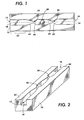
- Figure 2 is a perspective view, not to scale, of the channel 12 formed in section 10 as shown in the plan view of Figure 1.
- the channel of the present invention is formed in the surface of a substrate, such as a silicon chip, leading to a channel 12 having a rectangular cross-section.
- a substrate such as a silicon chip
- the use of a rectangular cross-section as shown in Figure 2 is effective at obtaining the desired impedances.
- the cross-sectional area of the flow path through fluid flow channel 12 can be kept constant despite the constrictions of channel diffusers 30 and 32, by using deeper channels with a rectanqular cross-section.
- dry-etching techniques such as reactive ion etching, on silicon or other materials.
- Channels can be formed in the surface of a silicon chip, as shown in Figure 2, and then another layer can be added over the main surface 60 of the chip as shown in Figure 2, in order to enclose the channel 12.
- An alternate technique is to form the desired profiles of channels 12 in a layer of polyimide, and sandwich this layer of polyimide between two silicon chips, one or both of which may include a heating element 20 defined therein in an appropriate place.
Landscapes
- Physics & Mathematics (AREA)
- Geometry (AREA)
- Particle Formation And Scattering Control In Inkjet Printers (AREA)
Abstract
Description
- The present invention relates to a printhead for a thermal ink-jet printer, in which the fluid flow channel of each ejector is specially shaped with impedance-controlling tapers, for optimal performance.
- In thermal ink-jet printing, droplets of ink are selectably ejected from a plurality of drop ejectors in a printhead. The ejectors are operated in accordance with digital instructions to create a desired image on a print sheet moving past the printhead. The printhead may move back and forth relative to the sheet in a typewriter fashion, or the linear array may be of a size extending across the entire width of a sheet, to place the image on a sheet in a single pass.
- The ejectors typically comprise capillary channels, or other ink passageways, which are connected to one or more common ink supply manifolds. Ink is retained within each channel until, in response to an appropriate digital signal, the ink in the channel is rapidly heated by a heating element disposed on a surface within the channel. This rapid vaporization of the ink adjacent the channel creates a bubble which causes a quantity of liquid ink to be ejected through an opening associated with the channel to the print sheet. The process of rapid vaporization creating a bubble is generally known as "nucleation." One patent showing the general configuration of a typical ink-jet printhead is US Patent no. 4,774,530, assigned to the assignee in the present application.
- In most designs of ejectors in ink-jet printheads currently in common use, the capillary channel which retains the liquid ink immediately prior to ejection is typically a simple tube of a uniform cross-section along its entire effective length. The channel may be round, square, or triangular in cross-section, but the cross-section does not vary at different points along the axis of the capillary channel. When a vapor bubble of liquid ink nucleates in such a channel, by the nature of the physics of nucleation, the expanding vapor bubble expands in all available directions. As a practical matter, such nucleation not only causes liquid ink disposed in the channel between the heating element and the nozzle to be pushed out of the nozzle, but also presents a force to liquid ink which is disposed between the heating element and the inlet to the capillary channel. In other words, in a standard-design ejector, nucleation pushes some ink out of the channel, but equally pushes a considerable quantity of ink "backwards" into the ink supply.
- This backward flow of liquid ink is a source of many practical disadvantages. First, the fact that one-half of the kinetic energy provided by the heating element is not used to eject toward the print sheet represents a waste of energy and a loss of drop velocity and drop volume. Further, the fact that liquid ink is pushed back into the ink supply with every ejection causes a requirement of more time for the capillary channel to re-fill with liquid ink, and therefore puts a significant constraint on the operating frequency of an individual ejector. In brief, this two-direction flow of ink with every ejection in the standard ejector introduces a trade-off between drop velocity and/or drop volume on one hand and re-fill speed on the other hand.
- The present invention proposes a design of an ink-jet ejector having a flow rectifier which minimizes the ratio of "backward" versus "forward" flow of liquid ink with each ejection.
- In the prior art, the article by Stemme and Stemme, "A Novel Piezoelectric Valveless Fluid Pump," The Seventh International Conference on Process Transducers. Yokohama, Japan (1993) pp. 110-113, which relates to PCT application WO-A-94/19609, discloses a diaphragm-type piezoelectric pump wherein fluid inlets and outlets include a constricting element having a larger pressure drop in one flow direction than in the opposite flow direction.
- US-A-4,368,477 discloses an ink-jet printhead in which individual ejectors are each provided with a diagonally-extending ink duct. The downstream end of each duct is formed with a wedge-shaped tapered portion, each having a leading edge wall carrying a discharge orifice for ink droplets.
- The present invention provides a thermal ink jet printhead as a thermal ink-jet printhead comprising at least one ejector, the ejector comprising: a structure defining a fluid flow channel for passage of liquid ink therethrough, the fluid flow channel being defined along an axis extending from an inlet to a nozzle; a heating element exposed within the fluid flow channel between the inlet and the nozzle and impedance means, including at least one tapered section in said fluid flow channel, providing an impedance to the flow of liquid ink which is greater between the heater element and the inlet than between the heater element and the nozzle.
- According to one embodiment of the present invention, there is provided a thermal ink-jet printhead comprising at least one ejector. The ejector comprises a structure defining a fluid flow channel for passage of liquid ink therethrough. The fluid flow channel is defined along an axis extending from an inlet to a nozzle. A heating element is exposed within the fluid flow channel between the inlet and the nozzle. The fluid flow channel defines a first taper in at least one dimension along the axis, the first taper being disposed between the heating element and the inlet and opening toward the nozzle.
- According to another embodiment of the present invention, there is provided a thermal ink-jet printhead comprising at least one ejector. The ejector comprises a structure defining a fluid flow channel for passage of liquid ink therethrough, the fluid flow channel being defined along an axis from an inlet to a nozzle. A heating element is exposed within the fluid flow channel between the inlet and the nozzle. The fluid flow channel defines a rear channel diffuser between the heating element and the inlet. The rear channel diffuser comprises a forward taper opening toward the nozzle and a rearward taper opening toward the inlet. A cone angle of each of the forward taper and rearward taper is selected so that flow impedance of liquid ink flowing through the rear channel diffuser toward the inlet is greater than flow impedance of liquid ink flowing through the rear channel diffuser toward the nozzle. According to another aspect of the invention, there is provided within the fluid flow channel a front channel diffuser between the heating element and the nozzle, the front channel diffuser comprising a forward taper opening toward the nozzle and a rearward taper opening toward the inlet, a cone angle of each of the forward taper and the rearward taper providing flow impedance of liquid ink flowing through the front channel diffuser toward the inlet greater than flow impedance of liquid ink flowing through the front channel diffuser toward the nozzle.
- However, it will be appreciated that other sources of energy may be used for causing ejection of liquid ink drops from the
channel 12. - Figure 1 is a plan view of a single ejector, as would be found in an ink-jet printhead, according to one embodiment of the present invention; and
- Figure 2 is a perspective view of the structure of a single ejector of Fig. 1.
- Figure 1 is a plan view of a single ejector (channel) as would be found in a thermal ink-jet printhead according to one embodiment of the present invention. As is well known, it is typical for ink-jet printheads to include a plurality of ejectors, typically 100 or more such ejectors, spaced at, for example, 300 to 600 ejectors to the linear inch (12 to 24 per mm). Also as is well known, each printhead is typically formed in a largely silicon structure, such as a silicon chip, having various voids etched therein to form capillary channels for the flow of liquid ink therethrough.
- With reference to Figure 1, a portion of a printhead chip, here indicated as 10, defines therein a fluid flow channel generally indicated as 12, which is aligned along an
axis 14. Thefluid flow channel 12 extends from aninlet port 16 to anozzle 18. As is known in the art of thermal ink-jet printheads, liquid ink from an external supply (not shown) is introduced intofluid flow channel 12 throughinlet 16, where it is retained largely by capillary force within thechannel 12 until it is ejected throughnozzle 18 and directed onto a print sheet. - The source of energy for ejecting liquid ink retained in
channel 12 throughnozzle 18 onto a print sheet is aheating element 20 in this embodiment. However, it will be appreciated that other sources of energy may be used for causing ejection of liquid ink drops from thechannel 12. In common designs of thermal ink-jet printheads,heating element 20 is in the form of an area of polysilicon which has been doped to a specific resistivity and which is covered with various protective passivation layers (not shown). Theheating element 20 is connected by conductive leads (not shown) to a voltage source, which is activated when it is desired to eject a droplet of ink at a particular moment.Heating element 20 thus serves as a resistance heater which, when activated by a voltage, nucleates liquid ink which is immediately adjacent the surface thereof. This nucleation creates a vapor bubble which begins directly on the surface ofheating element 20, and then expands as vaporization continues, and effectively pushes out liquid ink retained in thechannel 12 betweenheating element 20 andnozzle 18 until the vapor bubble collapses. - As mentioned above, when
heating element 20 creates a vapor bubble of liquid ink immediately adjacent thereto, not only will the expanding bubble created byheating element 20 push out liquid ink which is retained between theheating element 20 andnozzle 18, but by virtue of the equilibrium of pressure around the surface of a bubble, also push against liquid ink disposed betweenheating element 20 andinlet 16. When this ink is pushed against by the bubble, it follows that the ink will be pushed out of theinlet 16 and back into the ink supply. In order to minimize this undesirable back flow of liquid ink, the present invention proposes various flow-rectifying structures which influence the relative impedance to fluid flow alongaxis 14 to favor the flow of ink towardnozzle 18 as oppose to towardinlet 16. - In order to perform this adjustment of impedance, the present invention provides various tapers in the cross-section of
channel 12 alongaxis 14. According to the present invention, thechannel 12 defines arear channel diffuser 30 and afront channel diffuser 32. With reference torear channel diffuser 30, it can be seen thatdiffuser 30 comprises afirst taper 40 and asecond taper 42; with reference tofront channel diffuser 32, it can be seen that this diffuser comprises athird taper 44 and afourth taper 46. - For each of the rear channel diffuser 30 and the front channel diffuser 32, the intention of the two tapers is that the relatively slow first and third tapers toward the direction of the nozzle, and the relatively fast second and fourth tapers toward the direction of the inlet, have the function of creating a high impedance of ink flow from the
heater 20 in the direction toward theinlet 16, and a relatively low impedance for the flow of ink from theheater 20 toward the direction of thenozzle 18. Thus, therear channel diffuser 30 has a high impedance during the ejection of a droplet of liquid ink throughnozzle 18, and a low impedance for ink entering thechannel 12 throughinlet 16 during re-fill. With respect tofront channel diffuser 32, it will be seen that there will be a low impedance for ink being pushed through the diffuser toward thenozzle 18, but a higher impedance for any ink being drawn inward fromnozzle 18, which may occur in a manner to be described in detail below. - In one practical embodiment of the present invention, the preferred angles for the high-impedance tapers such as 40, 44 is not more than 30 degrees in total "cone angle," that is, from one wall of
channel 12 to the other. In general, in the context of ink-jet printing, 30 degrees has been found to be above the critical angle for the desired impedance effect, this being the angle at which the liquid ink releases from the wall ofchannel 12 at a given velocity. Under commonly-expected conditions of ink composition and ejection frequency, an optimum cone angle has been found to be about 10 degrees for the forward-facing tapers. With respect to thetapers - (As used in the claims herein, it will be understood that the "cone angle" refers to a taper of the fluid flow channel in at least one dimension, in the case of a fluid flow channel of rectangular cross-section; it will be understood that such a cone angle concept can apply equally to a semicircular or circular cross-section as well. Further, in certain of the claims, each of the
rear channel diffuser 30 andfront channel diffuser 32 are described as having forward facing and rearward facing tapers, forward facing tapers opening toward the nozzle and rearward-facing tapers opening toward the inlet.) - Thus, for a nucleating bubble of vaporized ink originating from
heating element 20, the liquid ink being pushed out from this bubble will face a high impedance fromtaper 40, and a relatively low impedance fromtaper 46. This lower impedance throughfront channel diffuser 32 will cause more ink to be pushed throughnozzle 18 than backwards towardsinlet 16, in the finite time of ejection before the vapor bubble collapses. In this way, the back flow towardinlet 16 is reduced with every ejection. - After the ejection of liquid ink from
nozzle 18, a new supply of liquid ink must be loaded intochannel 12 throughinlet 16. The nature oftaper 42 ofrear diffuser 30 creates a low-impedance flow into the bulk ofchannel 12. During the vapor bubble collapse, the high-impedance property oftaper 44 presents a high impedance for liquid ink to flow from the space inchannels 12 betweenfront channel diffuser 32 andnozzle 18, hence maximizing the re-use of bubble collapse energy for refill of the fluid flow channel throughinlet 16 anddiffuser 30. It follows that less liquid ink needs to be supplied by slow capillary refill action throughinlet 16, hence reducing the refill time and increasing the maximum print speed. - According to a preferred embodiment of the present invention, there is further provided within
channel 12 an extended portion generally indicated as 50, between thetaper 44 offront channel diffuser 32 andnozzle 18. Following the ejection of a droplet of liquid ink throughnozzle 18, the presence ofextension 50 will cause a small quantity of liquid ink to remain inchannel 12 even after ejection. This small quantity of liquid ink which will remain generally in the area ofextended portion 50 can serve as a liquid seal to enhance the speed and efficiency of the re-fill of liquid ink frominlet 16. The small remainder of liquid ink facilitated byextended portion 50 also prevents the undesirable intake of air during the re-fill stage: if any air is sucked back during the re-fill stage beyondfront channel diffuser 32, the presence of this stray air bubble before ejection will have an undesirable effect on the amount of ink ejected in the next ejection, and may also damage the printhead, if in the next ejection theheating element 20 has no liquid ink thereagainst to absorb heat energy. The extent ofextended portion 50 relative to the rest of thechannel 12 will vary by specific design, but as a general guideline, it is desirable that the extra volume to channel 12 provided byextended portion 50 be approximately equal to one-half the volume encompassed betweenheating element 20 andtaper 46. As a practical matter, what is important is thatextended portion 50 be long enough to cause a "bridge" of liquid ink, effectively sealingnozzle 18, to remain therein after each ejection. - With the channel design of the present invention, two key advantages are obtained: first, more ink is ejected through
nozzle 18 than throughinlet 16 with every ejection, and the flow of liquid ink to re-fill thechannel 12 after an ejection is enhanced. In the ongoing operation of a particular ejector, these two advantages have the effects of (a) increasing the kinetic energy of each droplet emitted through the nozzle; and (b) increasing the speed of re-fill, thereby increasing the maximum possible frequency of operation, which is the time between ejections. - The various trade-offs involved in designing a specific version of the ejector of the present invention can be summarized by the following equation:

- In general, it has been found that the design trade-off between droplet volume and droplet velocity summarized by the above equation can be manifest by the selection of neck width between the forward- and rearward-facing tapers for each diffuser. The presence of a front channel diffuser such as 32 may have the effect of decreasing the size of an ejected droplet relative to a straight-
sided channel 12 of similar dimensions. However, in some contexts, the emission of a smaller droplet of ink may be desirable from a standpoint of ink absorption by paper. - Figure 2 is a perspective view, not to scale, of the
channel 12 formed insection 10 as shown in the plan view of Figure 1. It will be noted that, according to presently-practical techniques of fabrication of ink-jet printheads, that the channel of the present invention is formed in the surface of a substrate, such as a silicon chip, leading to achannel 12 having a rectangular cross-section. Although it may be preferable to provide a nozzle having circular cross-section or semicircular cross-sections, the use of a rectangular cross-section as shown in Figure 2 is effective at obtaining the desired impedances. The cross-sectional area of the flow path throughfluid flow channel 12 can be kept constant despite the constrictions ofchannel diffusers - In order to obtain the desired profile of the
fluid flow channels 12 according to the present invention, it is preferred to use dry-etching techniques, such as reactive ion etching, on silicon or other materials. Channels can be formed in the surface of a silicon chip, as shown in Figure 2, and then another layer can be added over themain surface 60 of the chip as shown in Figure 2, in order to enclose thechannel 12. An alternate technique is to form the desired profiles ofchannels 12 in a layer of polyimide, and sandwich this layer of polyimide between two silicon chips, one or both of which may include aheating element 20 defined therein in an appropriate place.
Claims (10)
- A thermal ink-jet printhead comprising at least one ejector, the ejector comprising:a structure (10) defining a fluid flow channel (12) for passage of liquid ink therethrough, the fluid flow channel being defined along an axis (14) extending from an inlet (16) to a nozzle (18);a heating element (20) exposed within the fluid flow channel (12) between the inlet (16) and the nozzle (18); andimpedance means, including at least one tapered section (40-46) in said fluid flow channel, providing an impedance to the flow of liquid ink which is greater between the heater element (20) and the inlet (16) than between the heater element (20) and the nozzle (18).
- The printhead of claim 1, where said impedance means comprises in the fluid flow channel a first taper (40) in at least one dimension along the axis (14), the first taper (40) disposed between the heating element (20) and the inlet (16) and opening toward the nozzle (18).
- The printhead of claim 1 or 2, wherein the impedance means further comprises a second taper (46) in the fluid flow channel in at least one dimension along the axis (14), the second taper being disposed between the heating element (20) and the nozzle (18) and opening toward the inlet (16).
- The printhead of claim 1, 2 or 3, wherein the impedance means further comprises a third taper (42) in the fluid flow channel (12) in at least one dimension along the axis (14), the third taper being disposed between the heating element (20) and the inlet and opening toward the inlet (16).
- The printhead of any of claims 1 to 4, wherein the impedance means further comprises a fourth taper (44) in at least one dimension along the axis (14), the fourth taper being disposed between the heating element (20) and the nozzle (18) and opening toward the nozzle (18).
- The thermal ink-jet printhead of any of the preceding claims, wherein said impedance means comprises:
a rear channel diffuser (30) between the heating element (20) and the inlet (16), the rear channel diffuser comprising a forward taper (40) opening toward the nozzle (18) and a rearward taper (42) opening toward the inlet, a cone angle of each of the forward taper and the rearward taper being selected so that flow impedance of liquid ink flowing through the rear channel diffuser toward the inlet is greater than flow impedance of liquid ink flowing through the rear channel diffuser toward the nozzle. - The printhead of any of the preceding claims, wherein the impedance means further comprises a front channel diffuser (32) between the heating element (20) and the nozzle (18), the front channel diffuser comprising a forward taper (44) opening toward the nozzle and a rearward taper (46) opening toward the inlet, a cone angle of each of the forward taper and the rearward taper being selected so that flow impedance of liquid ink flowing through the front channel diffuser toward the inlet is greater than flow impedance of liquid ink flowing through the front channel diffuser toward the nozzle.
- The printhead of any of 5 to 7 claims, further comprising an extended portion between the fourth taper (44) or the forward taper of the front channel diffuser (32) and the nozzle (18), the extended portion encompassing a volume at least equal to one-half a volume encompassed by the fluid flow channel between the heating element (20) and the second taper (46) or the rearward taper of the front channel diffuser (32).
- The printhead of any of the preceding claims, wherein the cone angle of the first taper, fourth taper or forward taper is not more than 30 degrees.
- The printhead of any of the preceding claims, wherein the cone angle of the second taper, third taper or rearward taper of the front channel diffuser being not less than 30 degrees.
Applications Claiming Priority (2)
| Application Number | Priority Date | Filing Date | Title |
|---|---|---|---|
| US632293 | 1996-04-15 | ||
| US08/632,293 US5751317A (en) | 1996-04-15 | 1996-04-15 | Thermal ink-jet printhead with an optimized fluid flow channel in each ejector |
Publications (3)
| Publication Number | Publication Date |
|---|---|
| EP0802055A2 true EP0802055A2 (en) | 1997-10-22 |
| EP0802055A3 EP0802055A3 (en) | 1997-11-05 |
| EP0802055B1 EP0802055B1 (en) | 2001-10-04 |
Family
ID=24534927
Family Applications (1)
| Application Number | Title | Priority Date | Filing Date |
|---|---|---|---|
| EP97302529A Expired - Lifetime EP0802055B1 (en) | 1996-04-15 | 1997-04-14 | Thermal ink-jet printhead with an optimized fluid flow channel impedance |
Country Status (4)
| Country | Link |
|---|---|
| US (1) | US5751317A (en) |
| EP (1) | EP0802055B1 (en) |
| JP (1) | JPH1029311A (en) |
| DE (1) | DE69707043T2 (en) |
Cited By (1)
| Publication number | Priority date | Publication date | Assignee | Title |
|---|---|---|---|---|
| EP3322590A4 (en) * | 2015-07-14 | 2019-02-13 | Hewlett-Packard Development Company, L.P. | ANTIRETRET CHECK VALVE OF EJECTION CHAMBER OF SPRAYABLE MATERIAL |
Families Citing this family (18)
| Publication number | Priority date | Publication date | Assignee | Title |
|---|---|---|---|---|
| CN1274499C (en) * | 1998-01-23 | 2006-09-13 | 明碁电通股份有限公司 | A device that uses air bubbles as actual valves in micro-injectors that eject liquids |
| US6062681A (en) * | 1998-07-14 | 2000-05-16 | Hewlett-Packard Company | Bubble valve and bubble valve-based pressure regulator |
| US6322208B1 (en) * | 1998-08-12 | 2001-11-27 | Eastman Kodak Company | Treatment for improving properties of ink images |
| US6527378B2 (en) | 2001-04-20 | 2003-03-04 | Hewlett-Packard Company | Thermal ink jet defect tolerant resistor design |
| US6869273B2 (en) * | 2002-05-15 | 2005-03-22 | Hewlett-Packard Development Company, L.P. | Microelectromechanical device for controlled movement of a fluid |
| US6540337B1 (en) | 2002-07-26 | 2003-04-01 | Hewlett-Packard Company | Slotted substrates and methods and systems for forming same |
| US6672712B1 (en) * | 2002-10-31 | 2004-01-06 | Hewlett-Packard Development Company, L.P. | Slotted substrates and methods and systems for forming same |
| KR100499141B1 (en) * | 2003-01-15 | 2005-07-04 | 삼성전자주식회사 | Micro-pump driven by phase transformation of fluid |
| CN100446977C (en) * | 2004-08-11 | 2008-12-31 | 明基电通股份有限公司 | Fluid ejection device |
| US7591548B2 (en) * | 2005-09-29 | 2009-09-22 | Brother Kogyo Kabushiki Kaisha | Ink cartridge |
| KR100754392B1 (en) * | 2005-12-27 | 2007-08-31 | 삼성전자주식회사 | Ink flow structure of the inkjet printhead and the inkjet printhead having the same |
| KR20070097178A (en) * | 2006-03-28 | 2007-10-04 | 삼성전자주식회사 | Inkjet Printheads with Backflow Suppression Means |
| US20080061471A1 (en) * | 2006-09-13 | 2008-03-13 | Spin Master Ltd. | Decorative moulding toy |
| US7914125B2 (en) | 2006-09-14 | 2011-03-29 | Hewlett-Packard Development Company, L.P. | Fluid ejection device with deflective flexible membrane |
| US7651204B2 (en) * | 2006-09-14 | 2010-01-26 | Hewlett-Packard Development Company, L.P. | Fluid ejection device |
| US8042913B2 (en) * | 2006-09-14 | 2011-10-25 | Hewlett-Packard Development Company, L.P. | Fluid ejection device with deflective flexible membrane |
| US11685108B2 (en) * | 2018-08-06 | 2023-06-27 | Universiteit Twente | Method of 3D printing a cellular solid |
| CN115592948B (en) * | 2021-07-07 | 2026-03-03 | 上海傲睿科技有限公司 | Printhead containing internal micro-fluidic channel |
Family Cites Families (18)
| Publication number | Priority date | Publication date | Assignee | Title |
|---|---|---|---|---|
| JPS55100169A (en) * | 1979-01-25 | 1980-07-30 | Canon Inc | Liquid injection recording head |
| DE3019822A1 (en) * | 1980-05-23 | 1981-12-03 | Siemens AG, 1000 Berlin und 8000 München | ARRANGEMENT FOR A WRITING HEAD IN INK MOSAIC WRITING DEVICES |
| US4514742A (en) * | 1980-06-16 | 1985-04-30 | Nippon Electric Co., Ltd. | Printer head for an ink-on-demand type ink-jet printer |
| JPS5729463A (en) * | 1980-07-30 | 1982-02-17 | Nec Corp | Liquid jet head |
| DE3170016D1 (en) * | 1980-10-15 | 1985-05-23 | Hitachi Ltd | Ink jet printing apparatus |
| JPS57167273A (en) * | 1981-04-09 | 1982-10-15 | Nec Corp | Printing head |
| US4496960A (en) * | 1982-09-20 | 1985-01-29 | Xerox Corporation | Ink jet ejector utilizing check valves to prevent air ingestion |
| DE3402683C2 (en) * | 1983-01-28 | 1994-06-09 | Canon Kk | Ink jet recording head |
| US4550326A (en) * | 1983-05-02 | 1985-10-29 | Hewlett-Packard Company | Fluidic tuning of impulse jet devices using passive orifices |
| EP0145130B1 (en) * | 1983-08-31 | 1990-04-11 | Nec Corporation | On-demand type ink-jet print head having fluid control means |
| IT1178828B (en) * | 1984-01-20 | 1987-09-16 | Olivetti & Co Spa | SELECTIVE INK JET PRINTING DEVICE |
| US4723136A (en) * | 1984-11-05 | 1988-02-02 | Canon Kabushiki Kaisha | Print-on-demand type liquid jet printing head having main and subsidiary liquid paths |
| JPS62135378A (en) * | 1985-12-09 | 1987-06-18 | Nec Corp | Ink jet printing head |
| DE69130591T2 (en) * | 1990-06-15 | 1999-05-12 | Canon K.K., Tokio/Tokyo | Ink jet recorder and control method |
| US5041844A (en) * | 1990-07-02 | 1991-08-20 | Xerox Corporation | Thermal ink jet printhead with location control of bubble collapse |
| DE69214489T2 (en) * | 1991-03-20 | 1997-03-20 | Canon Kk | A liquid jet recording head and a liquid jet recording apparatus having the same |
| JP3083887B2 (en) * | 1991-10-17 | 2000-09-04 | キヤノン株式会社 | Ink jet recording head and recording device |
| US5278585A (en) * | 1992-05-28 | 1994-01-11 | Xerox Corporation | Ink jet printhead with ink flow directing valves |
-
1996
- 1996-04-15 US US08/632,293 patent/US5751317A/en not_active Expired - Lifetime
-
1997
- 1997-04-07 JP JP9087791A patent/JPH1029311A/en active Pending
- 1997-04-14 DE DE69707043T patent/DE69707043T2/en not_active Expired - Lifetime
- 1997-04-14 EP EP97302529A patent/EP0802055B1/en not_active Expired - Lifetime
Cited By (1)
| Publication number | Priority date | Publication date | Assignee | Title |
|---|---|---|---|---|
| EP3322590A4 (en) * | 2015-07-14 | 2019-02-13 | Hewlett-Packard Development Company, L.P. | ANTIRETRET CHECK VALVE OF EJECTION CHAMBER OF SPRAYABLE MATERIAL |
Also Published As
| Publication number | Publication date |
|---|---|
| DE69707043T2 (en) | 2002-02-14 |
| DE69707043D1 (en) | 2001-11-08 |
| US5751317A (en) | 1998-05-12 |
| JPH1029311A (en) | 1998-02-03 |
| EP0802055B1 (en) | 2001-10-04 |
| EP0802055A3 (en) | 1997-11-05 |
Similar Documents
| Publication | Publication Date | Title |
|---|---|---|
| EP0802055B1 (en) | Thermal ink-jet printhead with an optimized fluid flow channel impedance | |
| US5119116A (en) | Thermal ink jet channel with non-wetting walls and a step structure | |
| JP3706671B2 (en) | Liquid ejection head, head cartridge using liquid ejection head, liquid ejection apparatus, and liquid ejection method | |
| EP0694398B1 (en) | Ink jet printhead with tuned firing chambers and multiple inlets | |
| CN1274500C (en) | A device that uses air bubbles as actual valves in micro-injectors that eject liquids | |
| KR100554807B1 (en) | Method and apparatus for ink chamber evacuation | |
| US6481832B2 (en) | Fluid-jet ejection device | |
| JPH1052916A (en) | Inkjet printhead assembly with non-emission orifice | |
| JP3102324B2 (en) | INK JET PRINT HEAD, INK JET PRINTER, AND INK JET PRINT HEAD MAINTENANCE METHOD | |
| US10611144B2 (en) | Fluid ejection devices with reduced crosstalk | |
| EP0709212A1 (en) | Pen-based degassing scheme for ink jet pens | |
| JP3113123B2 (en) | Ink jet recording device | |
| US6508541B1 (en) | Thin front channel photopolymer drop ejector | |
| JP3093323B2 (en) | Ink jet recording head and ink jet recording apparatus using the head | |
| US6283580B1 (en) | Method of operation of an acoustic ink jet droplet emitter utilizing high liquid flow rates | |
| EP0873871A2 (en) | Thermal ink jet printhead suitable for viscous inks | |
| JP2883924B2 (en) | Thermal inkjet head | |
| JP3372826B2 (en) | Liquid ejection head and liquid ejection device | |
| JP3507421B2 (en) | Liquid discharge head, liquid discharge device, and liquid discharge method | |
| JP3459803B2 (en) | Recovery method and liquid ejection head | |
| JP2866261B2 (en) | Inkjet recording head | |
| JPH05278225A (en) | Ink jet recording apparatus | |
| JPH071729A (en) | Thermal ink jet print head | |
| HK1032564B (en) | Apparatus and method for using bubble as virtual valve in microinjector to eject fluid |
Legal Events
| Date | Code | Title | Description |
|---|---|---|---|
| PUAI | Public reference made under article 153(3) epc to a published international application that has entered the european phase |
Free format text: ORIGINAL CODE: 0009012 |
|
| PUAL | Search report despatched |
Free format text: ORIGINAL CODE: 0009013 |
|
| AK | Designated contracting states |
Kind code of ref document: A2 Designated state(s): DE FR GB |
|
| AK | Designated contracting states |
Kind code of ref document: A3 Designated state(s): DE FR GB |
|
| 17P | Request for examination filed |
Effective date: 19980506 |
|
| 17Q | First examination report despatched |
Effective date: 19990507 |
|
| GRAG | Despatch of communication of intention to grant |
Free format text: ORIGINAL CODE: EPIDOS AGRA |
|
| GRAG | Despatch of communication of intention to grant |
Free format text: ORIGINAL CODE: EPIDOS AGRA |
|
| GRAH | Despatch of communication of intention to grant a patent |
Free format text: ORIGINAL CODE: EPIDOS IGRA |
|
| GRAH | Despatch of communication of intention to grant a patent |
Free format text: ORIGINAL CODE: EPIDOS IGRA |
|
| GRAA | (expected) grant |
Free format text: ORIGINAL CODE: 0009210 |
|
| AK | Designated contracting states |
Kind code of ref document: B1 Designated state(s): DE FR GB |
|
| REF | Corresponds to: |
Ref document number: 69707043 Country of ref document: DE Date of ref document: 20011108 |
|
| REG | Reference to a national code |
Ref country code: GB Ref legal event code: IF02 |
|
| ET | Fr: translation filed | ||
| PLBE | No opposition filed within time limit |
Free format text: ORIGINAL CODE: 0009261 |
|
| STAA | Information on the status of an ep patent application or granted ep patent |
Free format text: STATUS: NO OPPOSITION FILED WITHIN TIME LIMIT |
|
| 26N | No opposition filed | ||
| PG25 | Lapsed in a contracting state [announced via postgrant information from national office to epo] |
Ref country code: FR Free format text: LAPSE BECAUSE OF NON-PAYMENT OF DUE FEES Effective date: 20041231 |
|
| REG | Reference to a national code |
Ref country code: FR Ref legal event code: ST |
|
| PGFP | Annual fee paid to national office [announced via postgrant information from national office to epo] |
Ref country code: DE Payment date: 20110406 Year of fee payment: 15 |
|
| REG | Reference to a national code |
Ref country code: FR Ref legal event code: D3 Effective date: 20120509 |
|
| PGRI | Patent reinstated in contracting state [announced from national office to epo] |
Ref country code: FR Effective date: 20120101 |
|
| REG | Reference to a national code |
Ref country code: DE Ref legal event code: R119 Ref document number: 69707043 Country of ref document: DE Effective date: 20121101 |
|
| PGFP | Annual fee paid to national office [announced via postgrant information from national office to epo] |
Ref country code: GB Payment date: 20140327 Year of fee payment: 18 |
|
| PGFP | Annual fee paid to national office [announced via postgrant information from national office to epo] |
Ref country code: FR Payment date: 20140422 Year of fee payment: 18 |
|
| PG25 | Lapsed in a contracting state [announced via postgrant information from national office to epo] |
Ref country code: DE Free format text: LAPSE BECAUSE OF NON-PAYMENT OF DUE FEES Effective date: 20121101 |
|
| GBPC | Gb: european patent ceased through non-payment of renewal fee |
Effective date: 20150414 |
|
| PG25 | Lapsed in a contracting state [announced via postgrant information from national office to epo] |
Ref country code: GB Free format text: LAPSE BECAUSE OF NON-PAYMENT OF DUE FEES Effective date: 20150414 |
|
| REG | Reference to a national code |
Ref country code: FR Ref legal event code: ST Effective date: 20151231 |
|
| PG25 | Lapsed in a contracting state [announced via postgrant information from national office to epo] |
Ref country code: FR Free format text: LAPSE BECAUSE OF NON-PAYMENT OF DUE FEES Effective date: 20150430 |