EP0802018A1 - Dispositif pour la rectification d'une face d'extrémité, particulièrement d'une face frontale, au bord d'un alésage d'une pièce - Google Patents
Dispositif pour la rectification d'une face d'extrémité, particulièrement d'une face frontale, au bord d'un alésage d'une pièce Download PDFInfo
- Publication number
- EP0802018A1 EP0802018A1 EP97106045A EP97106045A EP0802018A1 EP 0802018 A1 EP0802018 A1 EP 0802018A1 EP 97106045 A EP97106045 A EP 97106045A EP 97106045 A EP97106045 A EP 97106045A EP 0802018 A1 EP0802018 A1 EP 0802018A1
- Authority
- EP
- European Patent Office
- Prior art keywords
- shaft
- grinding tool
- grinding
- guide pin
- workpiece
- Prior art date
- Legal status (The legal status is an assumption and is not a legal conclusion. Google has not performed a legal analysis and makes no representation as to the accuracy of the status listed.)
- Granted
Links
- 239000004575 stone Substances 0.000 claims description 12
- 239000011248 coating agent Substances 0.000 claims description 10
- 238000000576 coating method Methods 0.000 claims description 10
- 230000006835 compression Effects 0.000 claims description 4
- 238000007906 compression Methods 0.000 claims description 4
- 230000037431 insertion Effects 0.000 claims 1
- 238000003780 insertion Methods 0.000 claims 1
- 230000000737 periodic effect Effects 0.000 abstract description 4
- 238000006073 displacement reaction Methods 0.000 description 7
- 238000003754 machining Methods 0.000 description 7
- 238000004519 manufacturing process Methods 0.000 description 3
- 230000001419 dependent effect Effects 0.000 description 2
- 238000002485 combustion reaction Methods 0.000 description 1
- 238000002347 injection Methods 0.000 description 1
- 239000007924 injection Substances 0.000 description 1
- 239000000463 material Substances 0.000 description 1
- 239000002184 metal Substances 0.000 description 1
- 239000003973 paint Substances 0.000 description 1
- 238000007789 sealing Methods 0.000 description 1
- 239000000725 suspension Substances 0.000 description 1
Images

Classifications
-
- B—PERFORMING OPERATIONS; TRANSPORTING
- B24—GRINDING; POLISHING
- B24B—MACHINES, DEVICES, OR PROCESSES FOR GRINDING OR POLISHING; DRESSING OR CONDITIONING OF ABRADING SURFACES; FEEDING OF GRINDING, POLISHING, OR LAPPING AGENTS
- B24B33/00—Honing machines or devices; Accessories therefor
- B24B33/055—Honing machines or devices; Accessories therefor designed for working plane surfaces
-
- B—PERFORMING OPERATIONS; TRANSPORTING
- B24—GRINDING; POLISHING
- B24B—MACHINES, DEVICES, OR PROCESSES FOR GRINDING OR POLISHING; DRESSING OR CONDITIONING OF ABRADING SURFACES; FEEDING OF GRINDING, POLISHING, OR LAPPING AGENTS
- B24B15/00—Machines or devices designed for grinding seat surfaces; Accessories therefor
- B24B15/02—Machines or devices designed for grinding seat surfaces; Accessories therefor in valve housings
-
- B—PERFORMING OPERATIONS; TRANSPORTING
- B24—GRINDING; POLISHING
- B24B—MACHINES, DEVICES, OR PROCESSES FOR GRINDING OR POLISHING; DRESSING OR CONDITIONING OF ABRADING SURFACES; FEEDING OF GRINDING, POLISHING, OR LAPPING AGENTS
- B24B33/00—Honing machines or devices; Accessories therefor
- B24B33/02—Honing machines or devices; Accessories therefor designed for working internal surfaces of revolution, e.g. of cylindrical or conical shapes
- B24B33/025—Internal surface of conical shape
Definitions
- the invention relates to a grinding device according to the preamble of claim 1.
- a known device of this type (DE 44 41 623 A1) is used for the fine machining of a bevel which is ground on the edge of the workpiece bore and which serves as a sealing seat for a valve needle.
- Such valve bores are provided, for example, in injection pumps for internal combustion engines. They have a very small diameter of only a few millimeters and have to be machined with high precision.
- the end face of the workpiece forming the edge of the bore or surrounding it must also be machined precisely; When sanding or when machining a chamfer, it must also be ensured that the frustoconical surface is exactly concentric to the axis of the hole.
- the known device For the surface processing of the chamfer, the known device has a conical grinding surface on the grinding tool, which is driven to rotate about the bore axis.
- the shape of the chamfer is directly dependent on the shape of the grinding surface of the grinding surface, which often has to be dressed in series production. Since grinding surfaces are generally inhomogeneous, the shape accuracy and the surface quality the chamfer in series production is inadequate for very high requirements.
- Plan honing devices are also known in which the honing tool with its abrasive coating is displaced on the surface to be machined. However, because of their relatively large dimensions, these devices cannot be used in confined spaces.
- the object of the invention is to implement the device with the smallest possible space requirement so that even small end faces, in particular ring faces at the edge of a bore, can be produced or machined with very high accuracy.
- the periodic shifting of the grinding tool transversely to the axis of the guide pin enables the surface of the end face of the workpiece and also the creation of a chamfer on the edge of the hole with a flat grinding surface, the shape of which is not changed by wear and dressing, so that a very high level in series production Accuracy and quality of the finished surface can be achieved.
- the displacement movement can be realized in a very small space, which results in a small size of the entire device.
- the grinding tool is expediently driven in rotation via a drive shaft, for example at 2000 to 6000 rpm, the periodic displacement being able to be generated by means of an eccentric, which is preferably part of a driven one Hollow shaft with an eccentric bore.
- the hollow shaft is preferably driven in the opposite direction to the drive shaft at a speed of 500 to 2000 rpm.
- the path of the transverse displacement is dimensioned such that the grinding surface completely sweeps over the end face to be machined, the distance when machining the surrounding area of very thin bores being, for example, 0.5 to 3 mm.
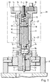
- the device according to FIGS. 1 to 3 has a grinding tool 1, which is designed as a honing stone 3 with a grinding coating 23 and is fastened to a holder 22.
- the holder 22 is a cylindrical slide, in which the honing stone 3 is inserted parallel to its axis, and which is arranged displaceably in a through opening 21 of a shaft 17.
- the shaft 17 is in one piece with a guide pin 7 executed, which dips into the finished honed bore 5 of a workpiece 6.
- the workpiece 6 is arranged in a known manner in a holding device 8 with a cardanic suspension of the workpiece clamping device, so that it is aligned precisely with its axis 2 by means of the guide pin 7, which axis coincides with the axis of the shaft 17.
- the shaft 17 forms the inner member of a telescopic drive shaft, the outer tube 10 of which is supported in a hollow shaft 9 by means of bearings 11 and 12.
- the shaft 17 is positively connected to the outer tube 10 in the direction of rotation of the drive shaft 10, 17 via a transverse bolt 19 which passes through the shaft 17 and has its ends in a longitudinal slot 18 of the outer tube 10.
- a compression spring 20 located within the outer tube loads the shaft 17 in the direction of the workpiece 6; its pretension is adjustable by means of an adjusting screw 30 which is inserted into the upper end of the outer tube 10.
- the shaft 17 is axially displaceable in the outer tube 10 when the compression spring 20 is loaded, the displacement path being limited by the length of the longitudinal slot 18.
- the drive shaft 10, 17 and the hollow shaft 9 are driven in opposite directions.
- the outer tube 10 of the drive shaft has an external toothing 15 at the upper end, and this upper end lies within a cup-shaped section 13 of the hollow shaft 9, which has an internal toothing 14 there.
- a drive pinion 16 engages in both toothings 14 and 15.
- the hollow shaft 9 has a bore 24 eccentric to the common axis 2 of the shafts and the guide pin within its lower section 9a, which thus forms an eccentric.
- the cylindrical slide 22 is in the through hole 21 of the shaft 17 arranged so that it rests with its two convex end faces 25 flat against the wall 26 of the eccentric bore 24 and is thus supported there in a sliding manner.
- the through-opening 21 is keyhole-shaped through a slot 21a extending into the guide pin 7, the slide 22 slidingly abutting the cylindrical wall of the through-opening 21, while the honing stone 3 lies within the slot 21a (FIG. 2).
- the honing stone 3 with the abrasive coating 23 projects outwards at both ends of the slot 21a (FIG. 1).
- the abrasive coating 23 can therefore completely paint over the end face 4 of the workpiece 6 to be machined with its abrasive surface 23a.
- the hollow shaft 9 is supported by means of bearings 27 in a device carrier 28 indicated by dash-dotted lines, which can be advanced axially in the direction of the workpiece 6 on guides (not shown).
- the carrier 28 and the holding device 8 are aligned with one another in such a way that the guide pin 7 is coaxial with the workpiece bore 5.
- the carrier 28 is then advanced in the direction of the workpiece 6, the guide pin 7 being immersed in the workpiece bore 5 which has been pre-machined or finished by honing.
- the gimbal-mounted workpiece 6 is aligned precisely with the axis 2, which then coincides with the axis of the bore.
- the guide pin 7 can be coated with a wear-resistant coating or also have guide strips 29 which are made of wear-resistant material, for example hard metal.
- the infeed can be controlled in a known manner depending on the route and also in a force-dependent manner, one gradual or continuous delivery is possible.
- the abrasive coating 23 of the honing stone 3 comes into contact with the annular surface 4 of the workpiece, the counter-rotating movements of the drive shaft 10, 17 and the hollow shaft 9 are initiated via the drive pinion 16.
- the delivery movement can be slowed down or briefly interrupted.
- the grinding surface 23a of the abrasive coating 23 bears against the workpiece surface 4, which is then machined by rotating movement and at the same time approximately radial, periodic displacement movements of the tool 1.
- the compression spring 20 is increasingly tensioned due to the further, continuous or step-by-step infeed.
- the feed movement is stopped as soon as the abrasive coating 23 of the honing stone 3 bears against the workpiece surface 4 under the pressure of the spring 20 with a predetermined machining force.
- the machining force to be specified can be set by specifying the infeed path, or - in the case of continuous infeed - by adjusting the spring force by means of the adjusting screw 30.
- Known path and / or force measuring devices can be provided to switch off the infeed when the predetermined final dimension is reached.
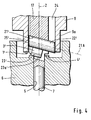
- Fig. 4 shows the device in the region of the machining zone in an enlarged partial axial section.
- a grinding tool 1 ' is provided with which a chamfer in the form of a conical ring surface 4' is ground at the edge of the workpiece bore 5.
- the chamfer 4 ' can be produced by means of the grinding tool 1' by removing the edge of the bore; However, the surface of an existing, previously created chamfer can also be finished to an exact dimension and exactly concentric to axis 2.
- the grinding tool 1 ' consists of a honing stone 3' provided with a grinding coating 23 ', which is inserted into a slide 22' as shown in FIG. 2.
- a through opening 21 'of the shaft 17 also extends into the guide pin 7, but extends with its central axis 21A of the upper region obliquely to the axis 2 of the guide pin 7.
- the cylindrical slide 22' is accordingly arranged obliquely in the shaft 17, so that its convex end faces 25 'are correspondingly beveled in axial section.
- the central axis of the slider 22 ' coincides with the axis 21A of the through opening, and the grinding surface 23a' of the grinding pad 23 'lies parallel to this axis 21A.
- the angle between the grinding surface 23a 'and the axis 2 corresponds to the target angle of the chamfer 4'.
- the honing stone 3 ' is dimensioned and arranged on the slide 22' in such a way that it extends partly into the workpiece bore 5 and completely covers the conical ring surface or chamfer 4 'during the turning and sliding movements of the tool 1'.
- the rotary and sliding movements are generated as described by means of the drive shaft and the outer hollow shaft 9.
Landscapes
- Engineering & Computer Science (AREA)
- Mechanical Engineering (AREA)
- Physics & Mathematics (AREA)
- Geometry (AREA)
- Finish Polishing, Edge Sharpening, And Grinding By Specific Grinding Devices (AREA)
- Grinding And Polishing Of Tertiary Curved Surfaces And Surfaces With Complex Shapes (AREA)
Applications Claiming Priority (2)
| Application Number | Priority Date | Filing Date | Title |
|---|---|---|---|
| DE29607203U | 1996-04-20 | ||
| DE29607203U DE29607203U1 (de) | 1996-04-20 | 1996-04-20 | Vorrichtung zum Schleifen einer Stirnfläche, insbesondere einer Ringfläche, am Rand einer Werkstück-Bohrung |
Publications (2)
| Publication Number | Publication Date |
|---|---|
| EP0802018A1 true EP0802018A1 (fr) | 1997-10-22 |
| EP0802018B1 EP0802018B1 (fr) | 2000-07-19 |
Family
ID=8022876
Family Applications (1)
| Application Number | Title | Priority Date | Filing Date |
|---|---|---|---|
| EP97106045A Expired - Lifetime EP0802018B1 (fr) | 1996-04-20 | 1997-04-12 | Dispositif pour la rectification d'une face d'extrémité, particulièrement d'une face frontale, au bord d'un alésage d'une pièce |
Country Status (4)
| Country | Link |
|---|---|
| US (1) | US6267653B1 (fr) |
| EP (1) | EP0802018B1 (fr) |
| JP (1) | JP3749777B2 (fr) |
| DE (2) | DE29607203U1 (fr) |
Cited By (2)
| Publication number | Priority date | Publication date | Assignee | Title |
|---|---|---|---|---|
| WO2000002705A1 (fr) * | 1998-07-10 | 2000-01-20 | Lidköping Machine Tools AB | Machine d'usinage par abrasion |
| WO2001008847A1 (fr) * | 1999-07-29 | 2001-02-08 | Prochniewicz Zbigniew | Tete d'outil conçue en particulier pour usiner des sieges de soupapes incorpores dans des moteurs a combustion |
Families Citing this family (9)
| Publication number | Priority date | Publication date | Assignee | Title |
|---|---|---|---|---|
| DE20311716U1 (de) | 2003-07-30 | 2003-10-30 | Hans Joachim Sauer (GmbH & Co), 22339 Hamburg | Vorrichtung zum Schleifen der Dichtfläche eines Dichtsitzes |
| DE102006012516A1 (de) * | 2006-03-18 | 2007-09-20 | Bayerische Motoren Werke Ag | Werkzeug zur Bearbeitung einer Dichtfase |
| JP4990643B2 (ja) * | 2007-02-13 | 2012-08-01 | トーヨーエイテック株式会社 | ホーニング加工装置 |
| US7861738B2 (en) * | 2008-03-04 | 2011-01-04 | Caterpillar Inc. | Remanufactured machine component and remanufacturing process |
| ES2332568B1 (es) * | 2008-07-23 | 2011-04-18 | Airbus Operations, S.L. | Sistema de repasado orbital post-afeitado de remaches. |
| JP5078971B2 (ja) * | 2009-11-13 | 2012-11-21 | 株式会社フジエ | 表面加工作業工具ユニット |
| CN102601730B (zh) * | 2012-03-28 | 2016-08-17 | 常州博瑞油泵油嘴有限公司 | 高压共轨喷油器针阀体精准定位夹紧装置 |
| CN102601729B (zh) * | 2012-03-28 | 2016-08-17 | 常州博瑞油泵油嘴有限公司 | 针阀体类零件轴向弹性精准定位夹紧装置 |
| CN115256211A (zh) * | 2022-08-17 | 2022-11-01 | 江苏威马悦达智能装备有限公司 | 一种阀体类零件专用珩磨刀具及其组装方法 |
Citations (4)
| Publication number | Priority date | Publication date | Assignee | Title |
|---|---|---|---|---|
| JPS59182055A (ja) * | 1983-03-31 | 1984-10-16 | Japan Electronic Control Syst Co Ltd | バルブシ−ト面の研削方法 |
| DE3627541A1 (de) * | 1986-08-13 | 1988-02-18 | Gehring Gmbh Maschf | Schleifvorrichtung |
| EP0399088A2 (fr) * | 1989-05-24 | 1990-11-28 | Alfredo Suarez Menendez | Dispositif de rodage |
| DE4441623A1 (de) * | 1993-12-15 | 1995-06-22 | Kopp Kadia Maschinenbau | Verfahren zum Feinschleifen einer Fase am Anfang einer Bohrung |
Family Cites Families (7)
| Publication number | Priority date | Publication date | Assignee | Title |
|---|---|---|---|---|
| US2226207A (en) * | 1938-07-22 | 1940-12-24 | Nomar Louis Nolan | Magazine rifle |
| US2443489A (en) * | 1946-05-06 | 1948-06-15 | Weynand Paul | Grinding tool |
| US2525119A (en) * | 1947-04-09 | 1950-10-10 | S & D Engineering Company | Valve-seat grinding means |
| US2754642A (en) * | 1952-05-14 | 1956-07-17 | Soulet Armand | Carrier for grindwheels for the truing of valve seats |
| US2809482A (en) * | 1953-04-10 | 1957-10-15 | Soulet Armand | Valve seat grinder |
| US2769287A (en) * | 1955-08-31 | 1956-11-06 | Tobin Arp Mfg Company | Valve seat grinder |
| US4467566A (en) * | 1982-01-29 | 1984-08-28 | Sunnen Products Company | Valve seat grinding device and tool for using same |
-
1996
- 1996-04-20 DE DE29607203U patent/DE29607203U1/de not_active Expired - Lifetime
-
1997
- 1997-04-12 DE DE59702039T patent/DE59702039D1/de not_active Expired - Lifetime
- 1997-04-12 EP EP97106045A patent/EP0802018B1/fr not_active Expired - Lifetime
- 1997-04-18 JP JP10198597A patent/JP3749777B2/ja not_active Expired - Fee Related
- 1997-04-18 US US08/844,706 patent/US6267653B1/en not_active Expired - Fee Related
Patent Citations (4)
| Publication number | Priority date | Publication date | Assignee | Title |
|---|---|---|---|---|
| JPS59182055A (ja) * | 1983-03-31 | 1984-10-16 | Japan Electronic Control Syst Co Ltd | バルブシ−ト面の研削方法 |
| DE3627541A1 (de) * | 1986-08-13 | 1988-02-18 | Gehring Gmbh Maschf | Schleifvorrichtung |
| EP0399088A2 (fr) * | 1989-05-24 | 1990-11-28 | Alfredo Suarez Menendez | Dispositif de rodage |
| DE4441623A1 (de) * | 1993-12-15 | 1995-06-22 | Kopp Kadia Maschinenbau | Verfahren zum Feinschleifen einer Fase am Anfang einer Bohrung |
Non-Patent Citations (1)
| Title |
|---|
| PATENT ABSTRACTS OF JAPAN vol. 009, no. 042 (M - 359) 22 February 1985 (1985-02-22) * |
Cited By (4)
| Publication number | Priority date | Publication date | Assignee | Title |
|---|---|---|---|---|
| WO2000002705A1 (fr) * | 1998-07-10 | 2000-01-20 | Lidköping Machine Tools AB | Machine d'usinage par abrasion |
| US6350187B2 (en) | 1998-07-10 | 2002-02-26 | Lidkoping Machine Tools Ab | Abrasive machine |
| CN1129505C (zh) * | 1998-07-10 | 2003-12-03 | 利德雪平机器工具公司 | 研磨机 |
| WO2001008847A1 (fr) * | 1999-07-29 | 2001-02-08 | Prochniewicz Zbigniew | Tete d'outil conçue en particulier pour usiner des sieges de soupapes incorpores dans des moteurs a combustion |
Also Published As
| Publication number | Publication date |
|---|---|
| DE59702039D1 (de) | 2000-08-24 |
| JPH1044010A (ja) | 1998-02-17 |
| JP3749777B2 (ja) | 2006-03-01 |
| US6267653B1 (en) | 2001-07-31 |
| EP0802018B1 (fr) | 2000-07-19 |
| DE29607203U1 (de) | 1997-08-14 |
Similar Documents
| Publication | Publication Date | Title |
|---|---|---|
| DE19830903B4 (de) | Einrichtung sowie Verfahren zur Bearbeitung von Bohrungen in einem Werkstück unter Verwendung einer solchen Einrichtung | |
| DE10234707A1 (de) | Verfahren und Vorrichtung zum Schleifen eines rotationssymmetrischen Maschinenbauteils | |
| DE2460997A1 (de) | Bearbeitungswerkzeug und -verfahren fuer bohrungen | |
| EP3921118B1 (fr) | Outil de rodage et procédé d'usinage de précision reposant sur l'utilisation de l'outil de rodage | |
| DE3227924C2 (fr) | ||
| EP0802018B1 (fr) | Dispositif pour la rectification d'une face d'extrémité, particulièrement d'une face frontale, au bord d'un alésage d'une pièce | |
| DE69506474T2 (de) | Vorrichtung zum Planen oder Polieren von steinigen Materialen | |
| EP0237790B1 (fr) | Dispositif de rodage | |
| DE4423422A1 (de) | Verfahren zur Außen-Feinstbearbeitung, insbesondere rotationssymmetrischer Körper | |
| DE3208536C2 (de) | Schleifmaschine | |
| EP0144786A1 (fr) | Dispositif de séparation | |
| DE29608877U1 (de) | Halterung für optische Linsen | |
| AT517140B1 (de) | Schleifwerkzeug | |
| DE2731554A1 (de) | Innenschleifvorrichtung | |
| DE102010036470A1 (de) | Vorrichtung zum universellen Honen von Laufflächen an Wälzlagerringen und Honsteinhalter für diese Vorrichtung | |
| EP0841116A2 (fr) | Méthode de travail de surfaces de pièces symétriques en rotation et outil employé | |
| DE20120294U1 (de) | Werkzeug | |
| DE2462847C2 (de) | Verfahren und Honmaschine zur Honbearbeitung von Bohrungen | |
| DE1279500B (de) | Innenschleifvorrichtung fuer lange Bohrungen | |
| EP4271538B1 (fr) | Procédé et dispositif d'usinage de précision de lentilles axicon, machine d'usinage de précision appropriée et utilisation y relative | |
| DE102004047520A1 (de) | Werkzeug zum Honen von Bohrungen mit absatzweise unterschiedlichem Durchmesser (Stufenbohrungen) | |
| DE2120519A1 (de) | Honwerkzeug | |
| DE3837172A1 (de) | Werkzeuganordnung zur bearbeitung von innenliegenden werkstueckoberflaechen | |
| DE102022207805A1 (de) | Honverfahren, Reinigungseinheit, Reinigungseinrichtung und Honmaschine | |
| EP0549820A1 (fr) | Tête de pierrage |
Legal Events
| Date | Code | Title | Description |
|---|---|---|---|
| PUAI | Public reference made under article 153(3) epc to a published international application that has entered the european phase |
Free format text: ORIGINAL CODE: 0009012 |
|
| AK | Designated contracting states |
Kind code of ref document: A1 Designated state(s): DE FR GB IT |
|
| 17P | Request for examination filed |
Effective date: 19970911 |
|
| 17Q | First examination report despatched |
Effective date: 19990326 |
|
| GRAG | Despatch of communication of intention to grant |
Free format text: ORIGINAL CODE: EPIDOS AGRA |
|
| GRAG | Despatch of communication of intention to grant |
Free format text: ORIGINAL CODE: EPIDOS AGRA |
|
| GRAH | Despatch of communication of intention to grant a patent |
Free format text: ORIGINAL CODE: EPIDOS IGRA |
|
| GRAH | Despatch of communication of intention to grant a patent |
Free format text: ORIGINAL CODE: EPIDOS IGRA |
|
| ITF | It: translation for a ep patent filed | ||
| GRAA | (expected) grant |
Free format text: ORIGINAL CODE: 0009210 |
|
| AK | Designated contracting states |
Kind code of ref document: B1 Designated state(s): DE FR GB IT |
|
| REF | Corresponds to: |
Ref document number: 59702039 Country of ref document: DE Date of ref document: 20000824 |
|
| ET | Fr: translation filed | ||
| GBT | Gb: translation of ep patent filed (gb section 77(6)(a)/1977) |
Effective date: 20000928 |
|
| PLBE | No opposition filed within time limit |
Free format text: ORIGINAL CODE: 0009261 |
|
| STAA | Information on the status of an ep patent application or granted ep patent |
Free format text: STATUS: NO OPPOSITION FILED WITHIN TIME LIMIT |
|
| 26N | No opposition filed | ||
| REG | Reference to a national code |
Ref country code: GB Ref legal event code: IF02 |
|
| PGFP | Annual fee paid to national office [announced via postgrant information from national office to epo] |
Ref country code: IT Payment date: 20080426 Year of fee payment: 12 |
|
| PGFP | Annual fee paid to national office [announced via postgrant information from national office to epo] |
Ref country code: FR Payment date: 20080418 Year of fee payment: 12 |
|
| PGFP | Annual fee paid to national office [announced via postgrant information from national office to epo] |
Ref country code: GB Payment date: 20080423 Year of fee payment: 12 |
|
| GBPC | Gb: european patent ceased through non-payment of renewal fee |
Effective date: 20090412 |
|
| REG | Reference to a national code |
Ref country code: FR Ref legal event code: ST Effective date: 20091231 |
|
| PG25 | Lapsed in a contracting state [announced via postgrant information from national office to epo] |
Ref country code: GB Free format text: LAPSE BECAUSE OF NON-PAYMENT OF DUE FEES Effective date: 20090412 Ref country code: FR Free format text: LAPSE BECAUSE OF NON-PAYMENT OF DUE FEES Effective date: 20091222 |
|
| PG25 | Lapsed in a contracting state [announced via postgrant information from national office to epo] |
Ref country code: IT Free format text: LAPSE BECAUSE OF NON-PAYMENT OF DUE FEES Effective date: 20090412 |
|
| PGFP | Annual fee paid to national office [announced via postgrant information from national office to epo] |
Ref country code: DE Payment date: 20110628 Year of fee payment: 15 |
|
| REG | Reference to a national code |
Ref country code: DE Ref legal event code: R119 Ref document number: 59702039 Country of ref document: DE Effective date: 20121101 |
|
| PG25 | Lapsed in a contracting state [announced via postgrant information from national office to epo] |
Ref country code: DE Free format text: LAPSE BECAUSE OF NON-PAYMENT OF DUE FEES Effective date: 20121101 |