EP0801243A2 - Hydrodynamic coupling - Google Patents
Hydrodynamic coupling Download PDFInfo
- Publication number
- EP0801243A2 EP0801243A2 EP97105665A EP97105665A EP0801243A2 EP 0801243 A2 EP0801243 A2 EP 0801243A2 EP 97105665 A EP97105665 A EP 97105665A EP 97105665 A EP97105665 A EP 97105665A EP 0801243 A2 EP0801243 A2 EP 0801243A2
- Authority
- EP
- European Patent Office
- Prior art keywords
- storage chamber
- housing
- working medium
- coupling according
- turbine wheel
- Prior art date
- Legal status (The legal status is an assumption and is not a legal conclusion. Google has not performed a legal analysis and makes no representation as to the accuracy of the status listed.)
- Granted
Links
- 230000008878 coupling Effects 0.000 title claims abstract description 28
- 238000010168 coupling process Methods 0.000 title claims abstract description 28
- 238000005859 coupling reaction Methods 0.000 title claims abstract description 28
- 238000003860 storage Methods 0.000 claims description 31
- 238000000034 method Methods 0.000 claims description 4
- 238000012544 monitoring process Methods 0.000 claims description 2
- 230000002093 peripheral effect Effects 0.000 claims 1
- 239000003570 air Substances 0.000 description 9
- 238000005192 partition Methods 0.000 description 4
- 238000001816 cooling Methods 0.000 description 3
- 238000009423 ventilation Methods 0.000 description 3
- 210000000078 claw Anatomy 0.000 description 2
- 230000017525 heat dissipation Effects 0.000 description 2
- 244000089486 Phragmites australis subsp australis Species 0.000 description 1
- 239000012080 ambient air Substances 0.000 description 1
- 230000006399 behavior Effects 0.000 description 1
- 230000005540 biological transmission Effects 0.000 description 1
- 230000003111 delayed effect Effects 0.000 description 1
- 239000012530 fluid Substances 0.000 description 1
- 238000007654 immersion Methods 0.000 description 1
- 238000005461 lubrication Methods 0.000 description 1
- 238000004519 manufacturing process Methods 0.000 description 1
- 238000005259 measurement Methods 0.000 description 1
- 239000000155 melt Substances 0.000 description 1
- 238000007493 shaping process Methods 0.000 description 1
- 229910000679 solder Inorganic materials 0.000 description 1
- 238000010408 sweeping Methods 0.000 description 1
Images


Classifications
-
- F—MECHANICAL ENGINEERING; LIGHTING; HEATING; WEAPONS; BLASTING
- F16—ENGINEERING ELEMENTS AND UNITS; GENERAL MEASURES FOR PRODUCING AND MAINTAINING EFFECTIVE FUNCTIONING OF MACHINES OR INSTALLATIONS; THERMAL INSULATION IN GENERAL
- F16D—COUPLINGS FOR TRANSMITTING ROTATION; CLUTCHES; BRAKES
- F16D33/00—Rotary fluid couplings or clutches of the hydrokinetic type
- F16D33/06—Rotary fluid couplings or clutches of the hydrokinetic type controlled by changing the amount of liquid in the working circuit
- F16D33/08—Rotary fluid couplings or clutches of the hydrokinetic type controlled by changing the amount of liquid in the working circuit by devices incorporated in the fluid coupling, with or without remote control
- F16D33/10—Rotary fluid couplings or clutches of the hydrokinetic type controlled by changing the amount of liquid in the working circuit by devices incorporated in the fluid coupling, with or without remote control consisting of controllable supply and discharge openings
Definitions
- the invention relates to a hydrodynamic coupling with a pump wheel and a turbine wheel, which form a toroidal working space with one another and which have a storage chamber.
- Hydrodynamic couplings with constant filling are generally used as start-up and overload clutches.
- the transmittable torque for a given slip is determined by the amount of oil filled and the drive speed.
- the starting torque can be reduced, for example, by a deceleration chamber.
- Working space and delay chamber are connected to each other via nozzles.
- working medium gets more or less quickly out of the delay chamber into the working area. In this way, the increase in torque over time can be influenced.
- This type of coupling offers the advantage of heat dissipation over the surface, since the parts surrounding the circuit rotate in air and can be optimized for cooling by suitable shaping.
- the invention has for its object to design a hydrodynamic coupling of the type defined in such a way that it fulfills its functions perfectly with little structural effort and low manufacturing costs, that the degree of filling of the work space can be controlled quickly and reliably, and that no external oil supply system is necessary .
- the transmissible torque of the clutch should be able to be changed arbitrarily during operation.
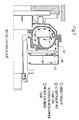
- Figure 1 shows a hydrodynamic coupling in an axial section.
- a pump wheel 1 and a turbine wheel 2 together form a toroidal working space.
- An inner housing 3 encloses part of the turbine wheel 2 with a trough-shaped wall 3.1.
- a first storage space 3.2 is provided at the radially inner end of the wall part 3.1. This is limited by an annular disc 3.3 against the turbine wheel.
- the inner housing also has a wall part 3.4. This is bulged so that it has the shape of an annular trough.
- a storage chamber 3.5 can also be seen. This is formed from a further wall part 3.6 and a partition 3.7. At the radially outer end of the partition 3.7 there is a bore 3.8. This creates a conductive connection between the tub and the storage chamber 3.5.
- a dynamic pressure pump 5 This has the shape of a pipe socket. At the radially outer end there is a mouthpiece 5.1. In the present case, the pipe socket runs perpendicular to the machine axis. He
- the dynamic pressure pump 5 is at its radially inner end in a conductive connection with the working space, which is formed from the pump wheel 1 and the turbine wheel 2. This is illustrated by the strongly drawn arrow. In this case, the conductive connection is established by a corresponding position of a rotary valve 6. Of course, any other type of valve could also be used.
- the housing 3 is surrounded by an outer housing 7.
- the entire hydrodynamic coupling is designed such that it can be connected to a drive motor 8 by being plugged on. From this one can see a housing 8.1 and a flywheel 8.2, to which an annular driver 8.3 is screwed.
- a plurality of driver claws 3.9 are formed on wall part 3.1.
- the outer housing 7 has special ventilation.
- an air inlet 9 between the motor 8 and the turbine wheel 2. This is formed from two annular disks 9.1 and 9.2, which form an annular, radial inlet channel.
- the inlet duct is connected to the outside environment through a plurality of bores, not shown, so that air can enter from the outside.
- the air flows around the radially inner edge of the annular disk 9.2, along the wall part 3.1, on which the air scoops are formed, and then exits the outer housing 7 through bores 9.3 to 9.7.
- Intensive cooling of the internal components of the hydrodynamic coupling takes place, namely by sweeping the cold air past the surface of the housing 3.
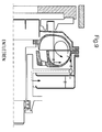
- FIGS. 4 to 9 illustrate further important embodiments of couplings according to the invention in a schematic representation.
- the essential parts of the coupling can also be seen here, namely the pump wheel 1, the turbine wheel 2, the dynamic pressure pump 5, the working chamber 21 and the pump chamber 22.
- the pump chamber 22 is here dimensioned such that the filling in the working space 21 is greatly reduced in the start-up state.
- the oil in the pump chamber 22 is skimmed off by the dynamic pressure pump 5 and fed to the working chamber 21 radially on the inside.
- the pump wheel 1 has nozzle bores 23, 24, via which a conductive connection between the working chamber 21 and the pump chamber 22 is established. By adjusting the nozzle bores accordingly and adjusting the valve accordingly (not shown here), the chronological course of the increase in torque can be determined until the working space 21 is completely filled.
- an additional storage space 25 is provided. This is delimited against the pump chamber 22 by a partition 3.7. Pump chamber 22 and additional storage chamber 25 are in conductive connection with one another via nozzle bores 26.
- the valve (not shown) in the pitot tube can optionally be switched such that the oil flows from the pump chamber 22 to the work chamber or to the additional storage space.
- the transferable torque of the clutch can be reduced - apart from the air ventilation torque - by suitable adjustment of the nozzle bores and the valve cross-section.
- a further storage space 1.1 is formed, which also serves to delay the start-up and thus to make it gentle.
- Motor 8 drives the flywheel 8.2. This takes the driver 8.3. From there, a torque is transmitted to the driving claws 3.9, and thus to the pump wheel 1. From the pump wheel 1, the torque is transmitted hydrodynamically to the turbine wheel 2, and from there to a shaft 10 and a V-belt pulley 11.
- the hydrodynamic coupling according to the invention works completely independently, that is, without an external oil supply system.
- the receiving volume of the storage chamber 3.5 is dimensioned according to the volume of the work area.
- the valve can be switched as desired from the outside, on the one hand in the two extreme positions, which are shown here, in order to establish a conductive connection between the dynamic pressure pump either with the working space or with the storage chamber 3.5.
- the valve 6 can also be set in intermediate positions, so that very different operating behaviors can be generated.
- Storage space 3.2 is in a conductive connection with the working space via an annular gap 12 between the turbine wheel 2 and the wall part 3.1. Since this is the only conductive connection between the storage space 3.2 and the work space, cooling of the work space after the standstill takes place is greatly delayed via the annular gap 12.
- the temperature of the working medium itself is measured.
- it is an oil. This means that a sensor is placed in the oil flow.
Abstract
Description
Die Erfindung betrifft eine hydrodynamische Kupplung mit einem Pumpenrad und einem Turbinenrad, die einen torusförmigen Arbeitsraum miteinander bilden, und die eine Speicherkammer aufweisen.The invention relates to a hydrodynamic coupling with a pump wheel and a turbine wheel, which form a toroidal working space with one another and which have a storage chamber.
Kupplungen dieser Art sind aus einer Vielzahl von Veröffentlichungen bekannt geworden. Arbeitsraum und Speicherkammer sind hierbei leitend miteinander verbunden. Die Speicherkammer gibt beim Anlaufen des Antriebsmotors mit einer gewissen Verzögerung Betriebsmittel an den Arbeitsraum ab, so daß die Drehmomentübertragung im Anfangsbereich sehr sanft stattfindet, so daß die beteiligten Komponenten, vor allem der Antriebsmotor, geschont werden. Auf die folgenden Dokumente wird verwiesen:
- (1) GB-A-922 415
- (2) GB-A-1 000 565
- (3) EP 062 274 A3
- (1) GB-A-922 415
- (2) GB-A-1 000 565
- (3) EP 062 274 A3
Hydrodynamische Kupplungen mit konstanter Füllung (Bauart T) werden in der Regel als Anfahr- und Überlastkupplung eingesetzt.Hydrodynamic couplings with constant filling (type T) are generally used as start-up and overload clutches.
Es besteht, entsprechend der Kennlinie der Turbokupplung, eine Abhängigkeit zwischen dem übertragenen Moment und dem sich zwischen Pumpenrad und Turbinenrad einstellenden Schlupf. Das übertragbare Moment bei einem vorgegebenen Schlupf wird durch die eingefüllte Ölmenge und die Antriebsdrehzahl bestimmt.There is, depending on the characteristic of the turbo coupling, a dependency between the transmitted torque and the slip that occurs between the pump wheel and the turbine wheel. The transmittable torque for a given slip is determined by the amount of oil filled and the drive speed.
Eine Änderung der Kupplungsfüllung im Betrieb um eine Änderung des Verhältnisses Moment/Schlupf bei gleichbleibender Antriebsdrehzahl sowie die Abkoppelung des Abtriebs ist nicht möglich.It is not possible to change the clutch charge during operation by changing the torque / slip ratio while the input speed remains the same or to disconnect the output.
Das Anfahrmoment kann beispielsweise durch eine Verzögerungskammer reduziert werden. Arbeitsraum und Verzögerungskammer stehen über Düsen miteinander in Verbindung. Je nach Dimensionierung der Düsen gelangt Arbeitsmedium mehr oder minder schnell aus der Verzögerungskammer in den Arbeitsraum. Hierdurch läßt sich der zeitliche Anstieg des Drehmomentes beeinflussen.The starting torque can be reduced, for example, by a deceleration chamber. Working space and delay chamber are connected to each other via nozzles. Depending on the dimensioning of the nozzles, working medium gets more or less quickly out of the delay chamber into the working area. In this way, the increase in torque over time can be influenced.
Diese Kupplungsbauart bietet den Vorteil der Wärmeabfuhr über die Oberfläche, da die kreislaufumschließenden Teile in Luft rotieren und durch geeignete Ausformung für die Kühlung optimiert werden können.This type of coupling offers the advantage of heat dissipation over the surface, since the parts surrounding the circuit rotate in air and can be optimized for cooling by suitable shaping.
Im Gegensatz zu Kupplungen mit konstanter Füllung an Arbeitsmedium gibt es auch Kupplungen, bei denen das Arbeitsmedium einem externen Behälter entnommen wird. Dabei sind die umlaufenden Kupplungsteile durch ein feststehendes, öldichtes Gehäuse umschlossen. Damit läßt sich der Füllungsgrad der Kupplung bei gleichbleibender Antriebsdrehzahl verändern, und damit auch das Moment-Schlupf-Verhältnis.In contrast to couplings with a constant filling of working medium, there are also couplings in which the working medium is taken from an external container. The circumferential coupling parts are enclosed in a fixed, oil-tight housing. This allows the degree of filling of the clutch to be changed while the drive speed remains the same, and with it the torque-slip ratio.
Diese Anwendungen werden in der Regel zur Verstellung der Abtriebsdrehzahl benutzt. Die entstehende Wärme wird über einen Externkühler abgeführt.These applications are usually used to adjust the output speed. The heat generated is dissipated via an external cooler.
Der Erfindung liegt die Aufgabe zugrunde, eine hydrodynamische Kupplung der eingangs definierten Art derart zu gestalten, daß sie bei geringem baulichen Aufwand und niedrigen Herstellungskosten ihre Funktionen einwandfrei erfüllt, daß der Füllungsgrad des Arbeitsraumes schnell und zuverlässig beherrschbar ist, und daß keine externe Ölversorgungsanlage notwendig ist. Insbesondere soll das übertragbare Moment der Kupplung während des Betriebes willkürlich verändert werden können.The invention has for its object to design a hydrodynamic coupling of the type defined in such a way that it fulfills its functions perfectly with little structural effort and low manufacturing costs, that the degree of filling of the work space can be controlled quickly and reliably, and that no external oil supply system is necessary . In particular, the transmissible torque of the clutch should be able to be changed arbitrarily during operation.
Diese Aufgabe wird durch die Merkmale von Anspruch 1 gelöst.This object is solved by the features of
Die Erfindung ist anhand der Zeichnungen näher erläutert.The invention is explained in more detail with reference to the drawings.
Figur 1 zeigt eine hydrodynamische Kupplung in einem Axialschnitt. Ein Pumpenrad 1 und ein Turbinenrad 2 bilden miteinander einen torusförmigen Arbeitsraum. Ein Innengehäuse 3 umschließt mit einer wannenförmigen Wandung 3.1 einen Teil des Turbinenrades 2. Am radial inneren Ende des Wandungsteiles 3.1 ist ein erster Stauraum 3.2 vorgesehen. Dieser ist durch eine Ringscheibe 3.3 gegen das Turbinenrad hin begrenzt. Das Innengehäuse weist ferner einen Wandteil 3.4 auf. Dieser ist ausgebaucht, so daß er die Gestalt einer ringförmigen Wanne hat. Man erkennt weiterhin eine Speicherkammer 3.5. Diese ist aus einem weiteren Wandteil 3.6 und einer Trennwand 3.7 gebildet. Am radial äußeren Ende der Trennwand 3.7 befindet sich eine Bohrung 3.8. Diese stellt eine leitende Verbindung her zwischen der genannten Wanne und der Speicherkammer 3.5.Figure 1 shows a hydrodynamic coupling in an axial section. A
Im Zwischenraum 4 zwischen dem Pumpenrad 1 und der Trennwand 3.7 befindet sich eine Staudruckpumpe 5. Diese hat die Gestalt eines Rohrstutzens. Am radial äußeren Ende befindet sich ein Mundstück 5.1. Im vorliegenden Falle verläuft der Rohrstutzen senkrecht zur Maschinenachse. ErIn the space 4 between the
könnte aber auch gegen die Senkrechte geneigt sein. Die Staudruckpumpe 5 steht an ihrem radial inneren Ende in leitender Verbindung mit dem Arbeitsraum, der aus dem Pumpenrad 1 und dem Turbinenrad 2 gebildet ist. Dies ist veranschaulicht durch den stark ausgezogenen Pfeil. Die leitende Verbindung ist in diesem Falle hergestellt durch eine entsprechende Position eines Drehventiles 6. Natürlich käme auch jede andere Art von Ventil in Betracht.but could also be inclined against the vertical. The
In den Figuren 2 und 3 hat das Drehventil eine andere Drehposition. Hierbei ist eine leitende Verbindung hergestellt zwischen der Staudruckpumpe 5 einerseits und der Speicherkammer 3.5 andererseits. Auch hier zeigt wiederum der stark ausgezogene Pfeil den Strömungsverlauf an. In Figur 3 erkennt man einen Drehmagneten 6.1, der das Ventil 6 betätigt.In Figures 2 and 3, the rotary valve has a different rotational position. Here, a conductive connection is established between the
Das Gehäuse 3 ist umgeben von einem Außengehäuse 7. Die gesamte hydrodynamische Kupplung ist derart gestaltet, daß sie durch aufstecken an einen Antriebsmotor 8 anschließbar ist. Von diesem erkennt man ein Gehäuse 8.1 sowie eine Schwungscheibe 8.2, an der ein ringförmiger Mitnehmer 8.3 angeschraubt ist. An Wandteil 3.1 sind eine Mehrzahl von Mitnehmerklauen 3.9 angeformt.The
Das Außengehäuse 7 weist eine besondere Belüftung auf. Zwischen dem Motor 8 und dem Turbinenrad 2 befindet sich Lufteinlaß 9. Dieser ist aus zwei Ringscheiben 9.1 und 9.2 gebildet, die einen ringförmigen, radialen Einlaßkanal bilden. Der Einlaßkanal ist durch eine Vielzahl von nicht dargestellten Bohrungen an die Außenumgebung angeschlossen, so daß von außen her Luft eintreten kann. Die Luft strömt um die radial innere Kante der Ringscheibe 9.2 herum, entlang dem Wandteil 3.1, dem Luftforderschaufeln angeformt sind, und tritt sodann durch Bohrungen 9.3 bis 9.7 aus dem Außengehäuse 7 wieder aus. Dabei findet eine intensive Kühlung der inneren Bauteile der hydrodynamischen Kupplung statt, und zwar durch Vorbeistreichen der kalten Luft an der Oberfläche des Gehäuses 3.The
Die Figuren 4 bis 9 veranschaulichen in schematischer Darstellung weitere wichtige Ausführungsformen von erfindungsgemäßen Kupplungen.FIGS. 4 to 9 illustrate further important embodiments of couplings according to the invention in a schematic representation.
Man erkennt auch hierbei wieder die wesentlichen Teile der Kupplung, nämlich das Pumpenrad 1, das Turbinenrad 2, die Staudruckpumpe 5, den Arbeitsraum 21 und den Pumpenraum 22. Der Pumpenraum 22 ist hierbei derart dimensioniert, daß die Füllung im Arbeitsraum 21 im Anfahrzustand stark reduziert ist. Das im Pumpenraum 22 befindliche Öl wird durch die Staudruckpumpe 5 abgeschöpft und dem Arbeitsraum 21 radial innen zugeführt. Das Pumpenrad 1 weist Düsenbohrungen 23, 24 auf, über die eine leitende Verbindung zwischen Arbeitsraum 21 und Pumpenraum 22 hergestellt wird. Durch die entsprechende Abstimmung der Düsenbohrungen sowie durch eine entsprechende Einstellung des Ventiles (hier nicht dargestellt) läßt sich der zeitliche Verlauf des Momentenanstieges bis zur völligen Füllung des Arbeitsraumes 21 festlegen.The essential parts of the coupling can also be seen here, namely the
Bei den Ausführungsformen gemäß der Figuren 7 bis 9 ist ein zusätzlicher Speicherraum 25 vorgesehen. Dieser ist gegen den Pumpenraum 22 durch eine Trennwand 3.7 abgegrenzt. Pumpenraum 22 und zusätzlicher Speicherraum 25 stehen über Düsenbohrungen 26 in leitender Verbindung miteinander. Das Ventil (nicht dargestellt) im Staurohr kann wahlweise derart geschaltet werden, daß das Öl aus dem Pumpenraum 22 zum Arbeitsraum oder zum zusätzlichen Speicherraum strömt.In the embodiments according to FIGS. 7 to 9, an
Durch geeignete Abstimmung der Düsenbohrungen und des Ventilquerschnittes kann das übertragbare Moment der Kupplung - bis auf das Luftventilationsmoment - reduziert werden.The transferable torque of the clutch can be reduced - apart from the air ventilation torque - by suitable adjustment of the nozzle bores and the valve cross-section.
Folgende weitere Merkmale sind wichtig oder gar wesentlich:
- * die Staudruckpumpe ist so ausgeführt, daß es auch bei größerer Eintauchtiefe einen geringen Strömungswiderstand bietet
- * die Staudruckpumpe ist als Rohr mit Rohrbogen oder als ringförmige Scheibe mit im Außendurchmesser tangental eingebrachten Öffnungen ausgeführt
- * die Staudruckpumpe ist mit zwei um 180° zueinander verdrehten Öffnungen ausgestattet, um eine Drehrichtungsunabhängigkeit zu erreichen
- * die Staudruckpumpe ist so dimensioniert, daß im ungedrosselten Zustand in jedem Betriebszustand die durch die verschiedenen Düsen angebotenen Ölmengen abgeschöpft werden können
- * die Schöpfschale und der Speicherraum sind für bessere Wärmeabfuhr an der Außenfläche verrippt
- * der Arbeitsraum, die Schöpfschale und der Speicherraum sind im Stillstand kommunizierende Gefäße
- * durch Lage und Größe von Speicherraum und Schöpfschale wird die Anfahrfüllung im Arbeitsraum und damit das Anfahrmoment bestimmt
- * durch geeignete Maßnahmen (WDR zwischen Schöpfschale und Speicherraum, radial nach oben gerichtete Staudruckpumpe, zum Arbeitsraum und Schöpfschale dicht schließendes Ventil, im Stillstand geschlossene Kugelventile in den radial außenliegenden Düsen zwischen Speicherraum und Schöpfschale) kann das Anfahrmoment auf das Niveau der Luftventilation reduziert werden
- * alternativ zu Düsen kann die Entleerung des Speicherraumes durch eine Staudruckpumpe erfolgen, die durch ein Ventil geschaltet werden kann
- * die Not-Aus-Funktion durch Schnellentleerventile zwischen Arbeitsraum und Pumpschale (Funktion "Arbeitsraum gefüllt" = SEV geschlossen durch Öl aus der Staudruckpumpe bewirkt)
- * die Lagerschmierung durch von der Staudruckpumpe versorgte Bohrungen
- * die Ventilfunktion schwarz-weiß, proportional oder getaktet
- * die Ventilausführung: Schieber-, Drehschieber-, Sitz-, Kolbenventil, Ventilklappe, einstellbare Drossel, Blende
- * die Ventilbetätigung: elektrisch, hydraulisch, pneumatisch, manuell, beliebige Kombination
- * die Temperaturüberwachung
- * dynamische Rückfüllung in die Schöpfschale und/oder den Speicherraum bei hohem Schlupf durch geeignete Bohrungen
- * stufenlose Verstellung der Abtriebsdrehzahl durch Änderung des Ventilquerschnitts
- * Anschlußmöglichkeit für externen Wärmetauscher.
- * the dynamic pressure pump is designed so that it offers a low flow resistance even with a greater immersion depth
- * the dynamic pressure pump is designed as a pipe with a pipe bend or as an annular disc with openings made tangentially in the outside diameter
- * the dynamic pressure pump is equipped with two openings rotated by 180 ° to one another in order to achieve a direction of rotation independence
- * The dynamic pressure pump is dimensioned so that in the unthrottled state, the oil quantities offered by the various nozzles can be skimmed off in any operating state
- * The scoop and the storage space are ribbed on the outer surface for better heat dissipation
- * The work area, the scoop and the storage area are communicating vessels when stationary
- * The position and size of the storage space and the scoop determine the start-up charge in the work area and thus the start-up torque
- * The starting torque can be reduced to the level of the air ventilation by means of suitable measures (WDR between the scoop and the storage space, a radially upward dynamic pressure pump, a valve that closes tightly to the work space and the scoop, ball valves closed at a standstill in the radially external nozzles between the storage space and the scoop)
- * As an alternative to nozzles, the storage space can be emptied using a dynamic pressure pump that can be switched by a valve
- * the emergency stop function thanks to quick drain valves between the work area and the pump bowl ("work area filled" function = SEV closed by oil from the dynamic pressure pump)
- * Bearing lubrication through holes supplied by the dynamic pressure pump
- * the valve function black and white, proportional or clocked
- * the valve design: slide valve, rotary slide valve, seat valve, piston valve, valve flap, adjustable throttle, orifice
- * Valve actuation: electrical, hydraulic, pneumatic, manual, any combination
- * temperature monitoring
- * Dynamic backfilling into the scoop and / or the storage space in case of high slip through suitable holes
- * Infinitely variable adjustment of the output speed by changing the valve cross section
- * Connection option for external heat exchanger.
Im radial inneren Bereich des Pumpenrades 1 ist ein weiterer Stauraum 1.1 gebildet, der ebenfalls dazu dient, das Anfahren zu verzögern und damit sanft zu gestalten.In the radially inner region of the
Der Kraftfluß verläuft wie folgt:
Motor 8 treibt die Schwungscheibe 8.2 an. Diese nimmt den Mitnehmer 8.3 mit. Von dort aus wird ein Drehmoment auf die Mitnehmerklauen 3.9 übertragen, und damit auf das Pumpenrad 1. Von Pumpenrad 1 erfolgt die Drehmomentübertragung hydrodynamisch auf das Turbinenrad 2, und von dort auf eine Welle 10 und eine Keilriemenscheibe 11.The power flow is as follows:
Motor 8 drives the flywheel 8.2. This takes the driver 8.3. From there, a torque is transmitted to the driving claws 3.9, and thus to the
Die hydrodynamische Kupplung gemäß der Erfindung arbeitet völlig autark, das heißt ohne eine externe Ölversorgungsanlage. Das Aufnahmevolumen der Speicherkammer 3.5 ist entsprechend dem Volumen des Arbeitsraumes bemessen.The hydrodynamic coupling according to the invention works completely independently, that is, without an external oil supply system. The receiving volume of the storage chamber 3.5 is dimensioned according to the volume of the work area.
Das Ventil läßt sich von außen her beliebig schalten, und zwar zum einen in den beiden Extrempositionen, die hier dargestellt sind, um eine leitende Verbindung zwischen der Staudruckpumpe entweder mit dem Arbeitsraum oder mit der Speicherkammer 3.5 herzustellen. Das Ventil 6 läßt sich aber auch in Zwischenpositionen einstellen, so daß sehr feinfühlig unterschiedliche Betriebsverhalten erzeugt werden können.The valve can be switched as desired from the outside, on the one hand in the two extreme positions, which are shown here, in order to establish a conductive connection between the dynamic pressure pump either with the working space or with the storage chamber 3.5. The
Stauraum 3.2 steht über einen Ringspalt 12 zwischen dem Turbinenrad 2 und dem Wandteil 3.1 mit dem Arbeitsraum in leitender Verbindung. Da dies die einzige leitende Verbindung zwischen dem Stauraum 3.2 und dem Arbeitsraum ist, findet über Ringspalt 12 eine sehr stark verzögerte Kühlung des Arbeitsraumes nach dem Stillstand statt.Storage space 3.2 is in a conductive connection with the working space via an
Bei geschlossenen hydrodynamischen Kupplungen mit konstanter Füllung ist es bekannt, Maßnahmen zu treffen, um Übertemperaturen des Arbeitsmediums nicht entstehen zu lassen, und damit eine Schädigung der Kupplung zu verhindern. Im allgemeinen verwendet man hierbei Schmelzsicherungsschrauben. Das eingebrachte Lot schmilzt bei einer definierten Temperatur; hierdurch wird das Arbeitsmedium aus dem Arbeitsraum entlassen.In the case of closed hydrodynamic couplings with constant filling, it is known to take measures in order not to allow excess temperatures of the working medium to arise, and thus to prevent damage to the coupling. In general, fuse screws are used. The solder introduced melts at a defined temperature; this releases the working fluid from the work area.
Bei den bekannten Kupplungen wird nicht etwa die Temperatur des Arbeitsmediums selbst gemessen, sondern diejenige der Umgebungsluft im Bereich der rotierenden Teile der Kupplung. Ein bestimmter Lufttemperaturwert wird dabei als Abschaltsignal ausgenutzt. Dieses Verfahren hat den Nachteil einer hohen Meßungenauigkeit sowie einer großen Trägheit. Außerdem erfordert dieses Verfahren in der Regel ein Abschalten des Antriebsmotors.In the known couplings, it is not the temperature of the working medium itself that is measured, but that of the ambient air in the area of the rotating parts of the coupling. A certain air temperature value is used as a shutdown signal. This method has the disadvantage of high measurement inaccuracy and great inertia. In addition, this method usually requires the drive motor to be switched off.
Gemäß der Erfindung wird die Temperatur des Arbeitsmediums selbst gemessen. Im allgemeinen handelt es sich, wie bekannt, um ein Öl. Dies bedeutet, daß ein Sensor im Ölstrom plaziert wird.According to the invention, the temperature of the working medium itself is measured. In general, as is known, it is an oil. This means that a sensor is placed in the oil flow.
Weiterhin wird gemäß der Erfindung bei Überschreiten eines bestimmten Temperaturwertes des Arbeitsmediums Arbeitsmedium aus dem Arbeitsraum abgezogen und in die Speicherkammer überführt. Ein Abschalten des Antriebsmotors ist somit nicht erforderlich. Dies hat den großen Vorteil, daß am Antrieb gegebenenfalls angebaute Nebenabtriebe unbeeinflußt weiterlaufen können.Furthermore, according to the invention, when a certain temperature value of the working medium is exceeded, working medium is withdrawn from the working space and transferred into the storage chamber. It is therefore not necessary to switch off the drive motor. This has the great advantage that if necessary, power take-offs installed on the drive can continue to run unaffected.
Claims (9)
Applications Claiming Priority (2)
| Application Number | Priority Date | Filing Date | Title |
|---|---|---|---|
| DE19614589A DE19614589A1 (en) | 1996-04-12 | 1996-04-12 | Hydrodynamic clutch |
| DE19614589 | 1996-04-12 |
Publications (3)
| Publication Number | Publication Date |
|---|---|
| EP0801243A2 true EP0801243A2 (en) | 1997-10-15 |
| EP0801243A3 EP0801243A3 (en) | 1998-07-01 |
| EP0801243B1 EP0801243B1 (en) | 2002-07-17 |
Family
ID=7791151
Family Applications (1)
| Application Number | Title | Priority Date | Filing Date |
|---|---|---|---|
| EP97105665A Expired - Lifetime EP0801243B1 (en) | 1996-04-12 | 1997-04-05 | Hydrodynamic coupling |
Country Status (3)
| Country | Link |
|---|---|
| US (1) | US6101810A (en) |
| EP (1) | EP0801243B1 (en) |
| DE (2) | DE19614589A1 (en) |
Cited By (4)
| Publication number | Priority date | Publication date | Assignee | Title |
|---|---|---|---|---|
| CN1331713C (en) * | 2003-12-23 | 2007-08-15 | 沃易斯涡轮股份有限公司 | Packaged unit with thermal fuse function |
| US7716925B2 (en) | 2003-12-23 | 2010-05-18 | Voith Turbo Gmbh & Co. | Closure with a thermal safeguard function |
| EP2479448A1 (en) * | 2011-01-18 | 2012-07-25 | Siemens Aktiengesellschaft | Hydrodynamic coupling with multi-stage pre-chamber |
| WO2018224428A1 (en) * | 2017-06-08 | 2018-12-13 | Voith Patent Gmbh | Hydrodynamic coupling |
Families Citing this family (12)
| Publication number | Priority date | Publication date | Assignee | Title |
|---|---|---|---|---|
| DE19802524B4 (en) | 1998-01-26 | 2005-12-22 | Voith Turbo Gmbh & Co. Kg | Hydrodynamic coupling |
| DE19902296A1 (en) * | 1999-01-21 | 2000-08-17 | Voith Turbo Kg | Hydrodynamic coupling comprises pump wheel and turbine wheel forming toroidal working space, sensors collecting data for operation of machine connected to coupling, and processor which lowers degree of filling of working space |
| DE102004006358B4 (en) * | 2004-02-09 | 2012-11-15 | Voith Turbo Gmbh & Co. Kg | Temperature controlled hydrodynamic machine |
| DE102004059833A1 (en) * | 2004-12-10 | 2006-06-14 | Voith Turbo Gmbh & Co. Kg | Method for controlling the maximum speed of a work machine and hydrodynamic coupling therefor |
| DE102005004524B3 (en) | 2005-01-31 | 2006-05-18 | Voith Turbo Gmbh & Co. Kg | Hydrodynamic clutch/brake for e.g. fan, has radially positioned dynamic pressure pump, which revolves with drive shaft of pump impeller and empties medium e.g. oil, from operating space such that propeller is in standstill |
| DE102007005429B4 (en) * | 2007-01-30 | 2009-06-25 | Voith Patent Gmbh | Hydrodynamic machine |
| KR100885549B1 (en) | 2007-06-14 | 2009-02-26 | 최쌍석 | Variable speed driving apparatus using water as working fluid |
| DE102007056495A1 (en) * | 2007-11-22 | 2009-04-23 | Voith Patent Gmbh | Hydrodynamic clutch, has impeller and turbine, which form torus-shaped work space with one another, and drawing disk provided with channels and arranged perpendicular to rotation axis of clutch |
| DE102008007046A1 (en) * | 2008-01-31 | 2009-08-06 | Voith Patent Gmbh | Method for controlling the power transmission of a hydrodynamic machine in a drive train and drive train |
| US20110054240A1 (en) * | 2009-09-03 | 2011-03-03 | Bender Eddie L | Induced Relaxation And Therapeutic Apparatus And Method |
| RU2523338C2 (en) * | 2012-01-27 | 2014-07-20 | Общество с ограниченной ответственностью "Конструкторское технологическое бюро "Техно-прогресс" | Hydrodynamic clutch controlled by filling change |
| DE102013219180A1 (en) * | 2013-09-24 | 2015-03-26 | Voith Patent Gmbh | Method for operating a drive train with a hydrodynamic coupling |
Citations (9)
| Publication number | Priority date | Publication date | Assignee | Title |
|---|---|---|---|---|
| US1859607A (en) * | 1928-10-17 | 1932-05-24 | Sinclair Harold | Hydraulic transmission gear and brake |
| DE867030C (en) * | 1943-11-23 | 1953-02-16 | Harold Sinclair | Flow clutch or friction clutch operated by centrifugal force of a fluid |
| DE874712C (en) * | 1940-02-17 | 1953-04-27 | Gen Motors Corp | Device for cooling the fluid coupling according to the Foettinger design that is connected between the engine and the transmission of motor vehicles |
| DE883377C (en) * | 1939-04-30 | 1953-07-16 | Voith Gmbh J M | Outlet control for flow circuits |
| GB747392A (en) * | 1951-02-28 | 1956-04-04 | Voith Gmbh J M | Improvements relating to hydraulic couplings |
| DE1037779B (en) * | 1954-09-25 | 1958-08-28 | Maschf Augsburg Nuernberg Ag | Fluid coupling |
| US3075354A (en) * | 1953-09-03 | 1963-01-29 | Sinclair Harold | Hydraulic turbo couplings |
| DE2305539A1 (en) * | 1972-02-11 | 1973-08-16 | Eclipse Consult | VALVE CONTROLLED HYDRAULIC CLUTCH |
| DE3047361A1 (en) * | 1980-12-16 | 1982-07-15 | Klöckner-Humboldt-Deutz AG, 5000 Köln | Air-cooled engine fan - has fluid coupling scoop outlet determined by thermostat controlled valve |
Family Cites Families (21)
| Publication number | Priority date | Publication date | Assignee | Title |
|---|---|---|---|---|
| US29928A (en) * | 1860-09-04 | Improvement in presses | ||
| DE7024735U (en) * | Fabbrica Automobili Isotta Fraschini E Motori Breda Spa | Fluid coupling and transmission | ||
| US2202243A (en) * | 1938-06-09 | 1940-05-28 | American Blower Corp | Cooling ribs-scoop controlled coupling |
| DE909272C (en) * | 1943-10-21 | 1954-04-15 | Voith Gmbh J M | Flow coupling with variable filling level |
| GB667565A (en) * | 1947-06-11 | 1952-03-05 | Ljungstroms Angturbin Ab | Improvements in the cooling of rotating bodies |
| DE1194207B (en) * | 1956-01-18 | 1965-06-03 | Harold Sinclair | Hydrodynamic coupling with changeable working chamber filling |
| US2831323A (en) * | 1956-09-13 | 1958-04-22 | American Radiator & Standard | Scoop and jet pump fluid regulating means for fluid couplings |
| GB922415A (en) * | 1958-09-22 | 1963-04-03 | American Radiator & Standard | Improvements in or relating to fluid couplings |
| US3045430A (en) * | 1960-09-20 | 1962-07-24 | John E Becker | Fluid couplings |
| US3157999A (en) * | 1962-09-05 | 1964-11-24 | Liquid Drive Corp | Fluid coupling |
| GB1000565A (en) * | 1963-04-02 | 1965-08-04 | American Radiator & Standard | Improvements in or relating to fluid couplings |
| US3405524A (en) * | 1967-02-13 | 1968-10-15 | American Radiator & Standard | Liquid level sensing and control means for fluid drives |
| DE2035539A1 (en) * | 1970-07-17 | 1972-01-20 | Kopo Apparatebau GmbH, 5630 Remscheid | Container |
| DE2757252C2 (en) * | 1977-12-22 | 1983-08-04 | Voith-Turbo Gmbh & Co Kg, 7180 Crailsheim | Fluid coupling |
| IT1145067B (en) * | 1981-04-06 | 1986-11-05 | Valeriano Fiorentini | HYDRODYNAMIC HYDRAULIC JOINT EQUIPPED WITH CONTROL MEANS |
| CA1209440A (en) * | 1982-06-22 | 1986-08-12 | John Elderton | Scoop-controlled fluid couplings |
| DE3240334C2 (en) * | 1982-10-30 | 1985-01-24 | Voith-Turbo Gmbh & Co Kg, 7180 Crailsheim | Hydrodynamic coupling |
| GB2156051B (en) * | 1984-02-03 | 1988-01-06 | Fluidrive Eng Co Ltd | Fluid couplings |
| DE3743292A1 (en) * | 1987-12-19 | 1989-06-29 | Porsche Ag | CLUTCH |
| DE4224728C2 (en) * | 1992-07-27 | 1998-01-15 | Voith Turbo Kg | Hydrodynamic clutch |
| US5426939A (en) * | 1993-06-28 | 1995-06-27 | Cottrell; Harold L. | Torque converter having automatic power control |
-
1996
- 1996-04-12 DE DE19614589A patent/DE19614589A1/en not_active Withdrawn
-
1997
- 1997-04-05 EP EP97105665A patent/EP0801243B1/en not_active Expired - Lifetime
- 1997-04-05 DE DE59707703T patent/DE59707703D1/en not_active Expired - Lifetime
- 1997-04-10 US US08/827,653 patent/US6101810A/en not_active Expired - Lifetime
Patent Citations (9)
| Publication number | Priority date | Publication date | Assignee | Title |
|---|---|---|---|---|
| US1859607A (en) * | 1928-10-17 | 1932-05-24 | Sinclair Harold | Hydraulic transmission gear and brake |
| DE883377C (en) * | 1939-04-30 | 1953-07-16 | Voith Gmbh J M | Outlet control for flow circuits |
| DE874712C (en) * | 1940-02-17 | 1953-04-27 | Gen Motors Corp | Device for cooling the fluid coupling according to the Foettinger design that is connected between the engine and the transmission of motor vehicles |
| DE867030C (en) * | 1943-11-23 | 1953-02-16 | Harold Sinclair | Flow clutch or friction clutch operated by centrifugal force of a fluid |
| GB747392A (en) * | 1951-02-28 | 1956-04-04 | Voith Gmbh J M | Improvements relating to hydraulic couplings |
| US3075354A (en) * | 1953-09-03 | 1963-01-29 | Sinclair Harold | Hydraulic turbo couplings |
| DE1037779B (en) * | 1954-09-25 | 1958-08-28 | Maschf Augsburg Nuernberg Ag | Fluid coupling |
| DE2305539A1 (en) * | 1972-02-11 | 1973-08-16 | Eclipse Consult | VALVE CONTROLLED HYDRAULIC CLUTCH |
| DE3047361A1 (en) * | 1980-12-16 | 1982-07-15 | Klöckner-Humboldt-Deutz AG, 5000 Köln | Air-cooled engine fan - has fluid coupling scoop outlet determined by thermostat controlled valve |
Cited By (4)
| Publication number | Priority date | Publication date | Assignee | Title |
|---|---|---|---|---|
| CN1331713C (en) * | 2003-12-23 | 2007-08-15 | 沃易斯涡轮股份有限公司 | Packaged unit with thermal fuse function |
| US7716925B2 (en) | 2003-12-23 | 2010-05-18 | Voith Turbo Gmbh & Co. | Closure with a thermal safeguard function |
| EP2479448A1 (en) * | 2011-01-18 | 2012-07-25 | Siemens Aktiengesellschaft | Hydrodynamic coupling with multi-stage pre-chamber |
| WO2018224428A1 (en) * | 2017-06-08 | 2018-12-13 | Voith Patent Gmbh | Hydrodynamic coupling |
Also Published As
| Publication number | Publication date |
|---|---|
| DE19614589A1 (en) | 1997-10-16 |
| US6101810A (en) | 2000-08-15 |
| DE59707703D1 (en) | 2002-08-22 |
| EP0801243A3 (en) | 1998-07-01 |
| EP0801243B1 (en) | 2002-07-17 |
Similar Documents
| Publication | Publication Date | Title |
|---|---|---|
| EP0801243B1 (en) | Hydrodynamic coupling | |
| DE3130871C3 (en) | Torque transmission device with a drive shaft rotating with superimposed torque vibrations | |
| DE602004001102T2 (en) | Hydraulically controlled propeller drive with integrated cooling | |
| DE2809847C2 (en) | Thermostat controlled clutch | |
| DE1922508A1 (en) | Control for an automatic gearbox | |
| EP1819932A1 (en) | Method for regulating the maximum speed of a working machine and associated hydrodynamic coupling | |
| DE102012219182B4 (en) | Transfer case device with a differential gear device | |
| DE102016116993A1 (en) | TRANSMISSION WITH FLUID DISTRIBUTION CLUTCH HUB | |
| EP2640618B1 (en) | Drive train with hydrodynamic retarder and brake torque setting method | |
| DE102006040506B4 (en) | Coupling device, in particular wet-running multi-plate clutch for a motor vehicle | |
| DE69913452T2 (en) | Graduated seal and bushing | |
| DE60011537T2 (en) | ARRANGEMENT OF A VEHICLE DRIVE SYSTEM | |
| DE3240334C2 (en) | Hydrodynamic coupling | |
| DE102011086376B4 (en) | Oil supply device for a multi-disc brake | |
| DE3322779C2 (en) | Fluid friction clutch | |
| DE4128791C2 (en) | Fluid friction clutch | |
| DE102007026141A1 (en) | Torque transfer device | |
| EP2861891B1 (en) | Method and device for lubricating fluid temperature control | |
| DE3504001A1 (en) | CONTROL SYSTEM FOR A DIRECT CLUTCH MECHANISM IN A DIRECT CLUTCH MECHANISM OF A HYDRAULIC POWER TRANSMISSION DEVICE OF A VEHICLE TRANSMISSION | |
| DE102011008250A1 (en) | Clutch control for a transmission | |
| EP1682790B1 (en) | Starting unit | |
| DE1425351B2 (en) | Synchronization control of a hydraulically operated friction clutch for a gearbox, in particular for motor vehicles | |
| DE102006011987A1 (en) | Drive train for commercial vehicle, has opening arranged in housing shell in such manner that during reversed power flow residual volume of fluid remains between impeller and housing shell | |
| DE2504057A1 (en) | DEVICE FOR HYDROKINETIC TORQUE TRANSMISSION | |
| DE112014006717B4 (en) | LOCK-UP CLUTCH FOR A TORQUE CONVERTER |
Legal Events
| Date | Code | Title | Description |
|---|---|---|---|
| PUAI | Public reference made under article 153(3) epc to a published international application that has entered the european phase |
Free format text: ORIGINAL CODE: 0009012 |
|
| AK | Designated contracting states |
Kind code of ref document: A2 Designated state(s): DE FR GB IT |
|
| PUAL | Search report despatched |
Free format text: ORIGINAL CODE: 0009013 |
|
| AK | Designated contracting states |
Kind code of ref document: A3 Designated state(s): DE FR GB IT |
|
| 17P | Request for examination filed |
Effective date: 19980714 |
|
| 17Q | First examination report despatched |
Effective date: 20001227 |
|
| GRAG | Despatch of communication of intention to grant |
Free format text: ORIGINAL CODE: EPIDOS AGRA |
|
| GRAG | Despatch of communication of intention to grant |
Free format text: ORIGINAL CODE: EPIDOS AGRA |
|
| GRAH | Despatch of communication of intention to grant a patent |
Free format text: ORIGINAL CODE: EPIDOS IGRA |
|
| GRAH | Despatch of communication of intention to grant a patent |
Free format text: ORIGINAL CODE: EPIDOS IGRA |
|
| GRAA | (expected) grant |
Free format text: ORIGINAL CODE: 0009210 |
|
| AK | Designated contracting states |
Kind code of ref document: B1 Designated state(s): DE FR GB IT |
|
| REG | Reference to a national code |
Ref country code: GB Ref legal event code: FG4D Free format text: NOT ENGLISH |
|
| GBT | Gb: translation of ep patent filed (gb section 77(6)(a)/1977) |
Effective date: 20020717 |
|
| REF | Corresponds to: |
Ref document number: 59707703 Country of ref document: DE Date of ref document: 20020822 |
|
| ET | Fr: translation filed | ||
| PLBE | No opposition filed within time limit |
Free format text: ORIGINAL CODE: 0009261 |
|
| STAA | Information on the status of an ep patent application or granted ep patent |
Free format text: STATUS: NO OPPOSITION FILED WITHIN TIME LIMIT |
|
| 26N | No opposition filed |
Effective date: 20030422 |
|
| PGFP | Annual fee paid to national office [announced via postgrant information from national office to epo] |
Ref country code: IT Payment date: 20130420 Year of fee payment: 17 |
|
| PG25 | Lapsed in a contracting state [announced via postgrant information from national office to epo] |
Ref country code: IT Free format text: LAPSE BECAUSE OF NON-PAYMENT OF DUE FEES Effective date: 20140405 |
|
| REG | Reference to a national code |
Ref country code: FR Ref legal event code: PLFP Year of fee payment: 19 |
|
| PGFP | Annual fee paid to national office [announced via postgrant information from national office to epo] |
Ref country code: GB Payment date: 20150420 Year of fee payment: 19 Ref country code: DE Payment date: 20150421 Year of fee payment: 19 |
|
| PGFP | Annual fee paid to national office [announced via postgrant information from national office to epo] |
Ref country code: FR Payment date: 20150421 Year of fee payment: 19 |
|
| REG | Reference to a national code |
Ref country code: DE Ref legal event code: R119 Ref document number: 59707703 Country of ref document: DE |
|
| GBPC | Gb: european patent ceased through non-payment of renewal fee |
Effective date: 20160405 |
|
| REG | Reference to a national code |
Ref country code: FR Ref legal event code: ST Effective date: 20161230 |
|
| PG25 | Lapsed in a contracting state [announced via postgrant information from national office to epo] |
Ref country code: FR Free format text: LAPSE BECAUSE OF NON-PAYMENT OF DUE FEES Effective date: 20160502 Ref country code: GB Free format text: LAPSE BECAUSE OF NON-PAYMENT OF DUE FEES Effective date: 20160405 Ref country code: DE Free format text: LAPSE BECAUSE OF NON-PAYMENT OF DUE FEES Effective date: 20161101 |