EP0801019A2 - Verfahren und Apparat zum Stapeln und Sammeln von Beuteln - Google Patents
Verfahren und Apparat zum Stapeln und Sammeln von Beuteln Download PDFInfo
- Publication number
- EP0801019A2 EP0801019A2 EP97302284A EP97302284A EP0801019A2 EP 0801019 A2 EP0801019 A2 EP 0801019A2 EP 97302284 A EP97302284 A EP 97302284A EP 97302284 A EP97302284 A EP 97302284A EP 0801019 A2 EP0801019 A2 EP 0801019A2
- Authority
- EP
- European Patent Office
- Prior art keywords
- fingers
- stacking
- path
- travel
- stack
- Prior art date
- Legal status (The legal status is an assumption and is not a legal conclusion. Google has not performed a legal analysis and makes no representation as to the accuracy of the status listed.)
- Withdrawn
Links
Images


Classifications
-
- B—PERFORMING OPERATIONS; TRANSPORTING
- B65—CONVEYING; PACKING; STORING; HANDLING THIN OR FILAMENTARY MATERIAL
- B65H—HANDLING THIN OR FILAMENTARY MATERIAL, e.g. SHEETS, WEBS, CABLES
- B65H31/00—Pile receivers
- B65H31/32—Auxiliary devices for receiving articles during removal of a completed pile
-
- B—PERFORMING OPERATIONS; TRANSPORTING
- B65—CONVEYING; PACKING; STORING; HANDLING THIN OR FILAMENTARY MATERIAL
- B65H—HANDLING THIN OR FILAMENTARY MATERIAL, e.g. SHEETS, WEBS, CABLES
- B65H31/00—Pile receivers
- B65H31/24—Pile receivers multiple or compartmented, e.d. for alternate, programmed, or selective filling
-
- B—PERFORMING OPERATIONS; TRANSPORTING
- B65—CONVEYING; PACKING; STORING; HANDLING THIN OR FILAMENTARY MATERIAL
- B65H—HANDLING THIN OR FILAMENTARY MATERIAL, e.g. SHEETS, WEBS, CABLES
- B65H2701/00—Handled material; Storage means
- B65H2701/10—Handled articles or webs
- B65H2701/19—Specific article or web
- B65H2701/191—Bags, sachets and pouches or the like
Definitions
- the present invention relates generally to the art of bag making equipment. More specifically, it relates to equipment for stacking and accumulating folded bags.
- Plastic or poly bags are currently made using high speed equipment that can form, perforate, separate, fold stack and wrap bags.
- the present invention is directed to stacking and temporarily accumulating the bags after they have been folded.
- bags After bags have been folded (typically single, double or triple folded) they are often stacked and then packaged. The stack ranges from five to twenty-five bags. The bags should be uniformly folded and stacked to work well with downstream automated wrapping equipment.
- One prior art stacker operates in conjunction with a triple folder, such as CMD Corporation's model 3013 triple folder.
- the bags are discharged from the triple folder with corrugating rolls.
- the corrugating rolls have upper discs that mesh with lower discs.
- the bag is given a corrugated shape. Bags with such a corrugated shape travel farther without support than do un-corrugated bags.
- a stacker hand is comprised of a number of fingers that catch the bags. After a few bags are caught, the hand retracts, dumping the bags on a conveyor where the remainder of the stack is formed. The hand then returns to a resting position, until it moves to begin catching the first few bags of the next stack. All bags after the first few are dropped from the folder to the stack on the conveyor. Diverters (vertical separators) on the conveyors separate adjacent stacks.
- a stacker that reduces the distance bags travel unsupported is desired.
- the stacker should be able to operate at a high rate of speed, preferably using pneumatics (rather than servo motors) to reduce the cost.
- the design will preferably have hands that catch the bags and travel different paths, so that a second hand can quickly move into position to catch bags after another hand has left that position. It is also desirable to have the hands that support the folded bags be capable of moving at multiple speeds so that they can travel as slow as possible, given the time constraints of the process.
- the stacker would preferably include an inspection device to reject improperly folded bags before the stack is made.
- the inspection should be adjustable for various widths and lengths of bags.
- a machine which can take stacks of folded bags from the stacker and accumulate the stacks to create a buffer for downstream equipment (such as a wrapper or automatic packager).
- the accumulator will preferably sense the number of stacks present and control the speed of the downstream equipment.
- Such a stacker and accumulator should preferably be capable of creating neat, proper stacks that are conveyed to downstream equipment such as an automatic packager.
- the stacks should be of a selectable count, and the bags should be allowed to be a variety of heights, lengths, and widths, film types, gauges, colors, fold configurations, and styles.
- a stacker will be modular, so different downstream equipment can be used with it.
- An apparatus for stacking objects is comprised of a first and second set of fingers in one embodiment of the invention.
- the fingers each have their own paths of travel, and move into and out of resting and stacking positions.
- the stacking position is formed by guides on 4 sides of the position.
- a pneumatic mover (such as an air cylinder) is coupled to the first set and/or second set of fingers.
- the first and second sets of fingers approach the stacking position from different directions.
- a conveyor is provided to transport the objects to the stacking position.
- a sensor is provided along the conveyor to detect objects that should be rejected.
- a height sensor is placed near the stacking station and senses when the stack of objects reaches a predetermined height. One set of fingers are then moved in-response to the stack reaching the predetermined height.
- a third set of fingers having a third path of travel are provided.
- the third path of travel is the same as the first path of travel.
- the first, second and third sets of fingers may be moved independently.
- the third set of fingers may be pneumatically moved.
- the second set of fingers are prestacking fingers, and the second path of travel is shorter than the other path of travel.
- Means for moving the first set of fingers into the stacking station after a stack has been started and for removing the second set of fingers from the stacking station before the stack is completed are provided.
- the first set of fingers may be moved at a plurality of speeds by a pneumatic mover.
- a method for stacking objects includes moving a first set of fingers into and out of a stacking position from a first direction. Also, a second set of fingers are moved into and out of a stacking position from a second direction. In one embodiment the steps of moving include the step of directing air into and out of an air cylinder.
- Another aspect of the invention includes the step of conveying the objects to the stacking position and detecting objects to be rejected. Also, in an alternative the height of the stack is sensed and one set of fingers is lowered when the stack reaches a predetermined height.
- a third set of fingers are moved into and out of the stacking position.
- the first and third sets fingers are moved along the same path.
- the first, second and third sets of fingers may be moved independently, and at a number of speeds.
- the second set of fingers are prestacking fingers and they are moved into the stacking position when a stack is to be started. They are then moved out before the stack is completed. The first or third sets of fingers are moved into the stacking position after the new stack is to be started. The movements may be accomplished pneumatically.
- Figures 1 and 2 show a stacker 101 and an accumulator 102 from a perspective view and side view, respectively.
- stacker 101 receives bags from a folding device 201 ( Figure 2) such as CMD Corporation's model 3013 triple folder.
- Stacker 101 stacks the bags, and when the stack reaches a predetermined number, the stacker is transferred to accumulator 102.
- the stack is held in accumulator 102 and then transferred to a downstream device, such as a Hayssen® wrapper.
- the bags may be folded in any style, and be comprised of a wide variety of materials. Also, a wide variety of dimensions of bags may be used.
- stacker 102 The operation of stacker 102 will be described in detail below with respect to Figures 1 and 2. It should be noted that the views are from opposite sides of the machine. Thus, in Figure 1 the bags to be stacked travel from right to left, while in Figure 2 the bags to be stacked travel from left to right.
- Stacker 101 includes a frame 105 ( Figure 1) that allows for adjusting the height of a pair of infeed rolls 106 and 107 (preferably from 43 to 48 inches from the floor).
- the adjustability allows infeed rolls 106 and 107 to be aligned with a pair of outfeed rolls 203 and 204 of folder 201.
- Ropes or belts 205 and 206 are guided by discharge rolls 203 and 204, respectively.
- corrugating rolls may be used to put a corrugation into each bag. This will help the bag travel in a straight line when unsupported.
- Infeed rolls 106 and 107 form a nip to receive an incoming bag 231 from folder 201.
- roll 106 may be slightly offset from roll 107.
- the position of roll 106 may be adjusted to open or close the nip, to allow for flexibility for variations in different bags.
- the nip will allow a bag 1/4 inch thick to pass through, in the preferred embodiment.
- Infeed rolls 106 and 107 each drive a set of ropes 108 and 109, respectively.
- Ropes 108 and 109 are preferably poly-urethane hollow tubes. The ends are spliced together with a steel barb for easy replacement. Ropes 108 are returned by a roll 112, and ropes 109 are returned by rolls 216 and 217.
- a folded bag 231 is discharged by folder 201 and caught in the nip between rolls 106 and 107 and transferred by ropes 108 and 109, past sensors 207 - 209 ( Figure 2).
- the preferred embodiment uses Sick brand, retro-reflective, photo eyes. The eyes emit a signal that is reflected back and sensed. When an object is between the eye and the reflector it will block that light and a signal is sent to a controller (such as a microprocessor). The eyes used have a lens that allows the detection of clear plastic material.
- the controller is not shown, but would include the necessary input and output connections in a manner well known in the art.
- Sensors 207-209 are used to detect improperly folded bags. When a bag is improperly folded it is too long in either the direction of travel, or two wide (perpendicular to but in the same horizontal plane as the direction of travel). Sensors 207 and 209 cooperate to detect bags that are too long. If the folded bag covers both sensors 207 and 209, then it is too long, and the controller causes the bag to be rejected. Sensors 207 and 209 are preferably located in the center of the bag.
- Sensor 208 cooperates with another sensor directly behind it (not shown).
- the sensors are offset from the center of the bag by equal amounts determined by the tolerance of the width. If sensor 208 or the other sensor detects the bag, then the bag is too wide, and subsequently rejected.
- the locations of the sensors are adjustable, so that bags of different lengths and widths may be accommodated.
- Rejected bags are disposed of along a path shown by arrow 213 ( Figure 2).
- Ropes 109 make a downward turn at roll 216, and cooperate with a set of ropes 114 to form the rejection path. Both ropes 114 and 109 have a downward direction along the rejection path.
- the rejected bags are directed into the rejection path by a blast of air from an air pipe 214.
- Air pipe 214 can be located either upstream or downstream of roll 112, and need only be positioned to insure that rejected bags will follow the rejection path.
- the rejection of bags can be continuous (if the user so desires) or automatic as described above. Also, if the downstream equipment (such as a Hayssen® wrapper) cannot keep up with the incoming bags, then even good bags can be rejected. Because the rejected bags are discharged toward the floor, access is preferably provided between framing 105 to allow access to the rejected bags.
- Ropes 116 and 218 are carried between two sets of ropes 116 and 218.
- Ropes 116 travel around roll 112 and a roll 117
- ropes 218 travel around roll 212 and a roll 219.
- Ropes 114 and 218 share a common roll 212, even though they travel in opposite directions.
- Roll or shaft 212 has some pulleys that are driven (and cooperate with ropes 218) and others that are idlers (and cooperate with ropes 114) to allow for the opposite directions of travel.
- Roll 112 is shown to be driven by a gear reducer 222 and motor 223. All the rolls that are driven, are done so by motor 223, although the connections are not shown for clarity. Of course, other arrangements of rolls, ropes, belts, motors, gear reducers and pulleys could be used.
- Sensor 221 is also a photo eye and is used to count bags. The number of bags that are not rejected, and thus stacked, is kept track of. The user can select the number of bags in each stack (from 5 to 25 in the preferred embodiment, although other ranges may be used). When the selected number of bags are counted by sensor 221 the trailing edge of the last bag is sensed, and based on that the stacking operations (described later) are initiated. Sensor 221 is located close to rolls 117 and 219 to allow accurate initiation of the stacking operations. In alternative embodiments one of sensors 207-209 is used to count the bags and sense the trailing edge.
- the preferred embodiment uses three sets of fingers, 226, 227 and 229. Fingers 226 and 227 are used for stacking and fingers 229 are used for prestacking. Stacking fingers 226 and 227 follow a single clockwise rectangular path, as shown by arrows 230A-230D. In an alternative embodiment fingers 226 and 227 follow different paths. Stacking fingers 226 are shown in a stacking position and fingers 227 are shown in a resting position. Other positions 235 and 236 for stacking fingers 226 and 227 are shown with dashed lines.
- Fingers 229 are shown in a resting position. Prestacking fingers 229 follow a counter-clockwise rectangular path, (different from that of stacking fingers 226 and 227) as shown by arrows. The arrows indicate that, in the preferred embodiment, not only do fingers 229 follow a different path than fingers 226 and 227, they approach the stacking position from different directions, and thus fingers 226 and 227 do not interfere with the movements of fingers 229.
- the three sets of fingers interact to insure that bags are always supported, and that the incoming bags can operate at high speeds.
- stacking fingers 226 catch the bags (shown as 231) as they leave ropes 116 and 218.
- the fingers are in the positions shown in figure 2 in the middle of a cycle, i.e. after a stack has been started, but before it is completed.
- the bags 231 are guided into a proper position by a set of vertical bars 233 at the downstream end of stacking fingers 226.
- a set of vertical bars 234 contain the upstream end of the bags.
- a pair of side plates prevent the bags from being displaced in the cross direction.
- Bars 233 and 234 are used rather than plates to allow the fingers to travel through them.
- Another sensor is positioned to sense bags 231 stacked on fingers 226, at a height near (preferably less than two inches below) that of roll 219 and detects the top of the stack of bags.
- the controller causes fingers 231 to be lowered.
- the controller requires that the eye be blocked for greater than a predetermined time to distinguish bags falling past the sensor.
- fingers 226 are lowered until the eye stops detecting a bag. This arrangement reduces the distance the bags fall before being stacked on fingers 226 and keeps the top of the stack at about the same height to give consistent stacking.
- the stack typically increments by about one half inch to one inch, and the distance each bag has to fall to the stack is preferably 2 inches or less.
- the stack is incremented down a predetermined amount for each bag (or some number of bags). The process continues until the user-set number of bags have been stacked (as counted with sensor 221).
- prestacking fingers 229 move directly down from the resting position to catch bags to be stacked (the prestacking position).
- the prestacking position is at or near the position in which fingers 226 are shown in Figure 2.
- the distance prestacking fingers 229 move is relatively little (about two inches in the preferred embodiment). Because they travel such a short distance fingers 229 can be in position to catch bags before the first bag in each stack arrives. The short distance also allows use of pneumatics to move the fingers, rather than a costly and complex servo motor.
- an air pipe is provided to direct a blast of air straight down on the last bag of a stack, to insure the tail of the bag is onto the stack before the prestacking fingers move into position.
- prestacking fingers 229 When prestacking fingers 229 reach the prestacking position, stacking fingers 227 (in the resting position) begin to move to the stacking position. After a slight delay prestacking fingers 229 are retracted to the right, leaving stacking fingers 227 holding the bag(s). The slight delay is provided so that the bags are always supported. Prestacking fingers 229 then complete the travel to the right, clearing the bags, and move up, and then return to the resting position (shown in Figure 2).
- prestacking fingers 229 move quickly and catch the first bags of each stack while the stacking fingers are moving into position. This reduces the need for servo motors to move the fingers.
- servo motors are used to move one or more sets of fingers.
- Another alternative is to use only two sets of fingers that either follow different paths or they follow the same path and one set always acts as a prestacker and catches the first few bags in each stack.
- the prestacking fingers cooperate with the stacking fingers and because they follow a different path, they do not interfere with each others movements.
- Stacking fingers 226 and 227 follow a clockwise path, while prestacking fingers 229 follow a counter-clockwise path.
- fingers 226 move to position 236, which places the stack of bags on a set of ropes 240, which are guided by a pair of rolls 241 and 242. Fingers 226 then retract to position 235, and then travel to the resting position, assuming it has been cleared by the other stacking fingers.
- a complete cycle for one set bf stacking fingers would be to begin at rest in the position occupied by fingers 227 in Figure 2, and then move to the stacking position when the previous stack is completed.
- the stacking fingers travel about 12 inches to reach the stacking position (much more than the two inches the prestacker has to travel).
- the fingers increment down as bags are added to the stack.
- the bags are deposited on ropes 240, and the fingers return to the rest position.
- prestacking fingers 229 have made two complete cycles, one for each set of stacking fingers.
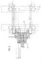
- Figure 3 is a side view of the fingers mounted on frame 105.
- Stacking fingers 226 are shown in a position below prestacking fingers 229.
- Vertical bars 233 and 234 are shown, and one side plate 301, that form the space within which the bags are stacked.
- the distances between the side plates and vertical bars may be adjustable, to accommodate a wide range of bag sizes.
- Figure 4 shows that fingers 229 are comprised of a plurality of bars having spaces therebetween.
- Figure 5 shows a top view of fingers 226 and 229 mounted on frame 105. Fingers 229 and 226 follow different paths and, as shown, do not interfere with the other's movements.
- the fingers are controlled with an XY pneumatic positioner. This avoids using a costly and complex servo motor.
- the speed of each motion is controlled by flow control.
- the piping and flow control for the stacking fingers is such that they can move up or down, and the down motion can be in increments or at three different speeds.
- Three speeds are obtained by using a 4-way, double solenoid 3 position, 5 port valve, such as model H243 available from Humphrey.
- the valve has a holding position in the center so that when its unactuated, it will hold a mid-stroke position (for incrementing).
- the exhaust port of that valve is diverted to three additional parallel valves.
- Each of the three additional valves have a flow control associated with its exhaust.
- the valve selected (and associated flow control) determines the speed of the movement.
- 2 or 3-way valves or valves that control the flow themselves may be used.
- the valves are operated such that when a stack of bags is incrementing down towards position 236 the fingers move slowly.
- the fingers move at one of three speeds: low, medium or high, to set that stack down onto ropes 240.
- the speed is determined by the number of bags the user selected to place in each stack. For larger stacks (and lesser distances) the speed is slower. Alternatively, the speed of the downstroke may be directly selected by the user. After depositing the stack the fingers move at high speed back to the rest position.
- a 4-way valve 801 has output ports connected to an air cylinder 802 through hoses 804 and 805. Air cylinder 802 is linked to and moves one set of stacking fingers. Valve 801 has an exhaust port with a muffler 806 when the speed at which fingers travel does not need to be limited (for example when the fingers return to the resting position from position 235). An input port is connected to an air supply through a hose 807.
- An exhaust port is connected to hose 808, for controlling the speed of the fingers when they are carrying a stack of bags.
- a hose 809 is connected to hose 808 and leads to a valve 810.
- Valve 810 has a flow control 811 on its exhaust, and a muffler 812 is attached to flow control 811.
- Flow control 811 is set to provide a slow speed, thus valve 810 is opened when a slow speed is desired.
- valve 815 is connected to hose 808 and leads to a valve 815.
- Valve 815 has a flow control 816 on its exhaust, and a muffler 817 is attached to flow control 816.
- flow control 816 is set to provide a medium speed, thus valve 815 is opened when a medium speed is desired.
- a hose 819, valve 820, flow control 821 and muffler 822 are similarly arranged. However flow control 821 is selected for high speed operation.
- ropes 240 are intermittently moved, in cooperation with a set of ropes 243 which are guided by a pair of rolls 244 and 245. After a stack of bags have been deposited on ropes 240, ropes 240 and 243 begin moving and the stack of bags is advanced to position 250. If a stack had been at position 250 it is advanced to accumulator 102.
- the bags When the bags are at position 250 they are directly beneath a pneumatic squasher 251.
- Pneumatic squasher 251 moves downward and applies pressure to the top of the stack.
- a plate 252 underneath the ropes supports the stack so squasher 251 creases the bags, thus creating a cradle which is perpendicular to the direction of travel.
- the cradle makes the stack more stable so that as it is intermittently moved it has less tendency to tip over or so the bags have less tendency to slide and create a sloppy stack.
- the squasher includes fingers which shape the cradle.
- the fingers may be curved to control the arc of the cradle, or the fingers may be flat to flatten the stack.
- Accumulator 102 includes rolls 602-611 mounted on framing 601. Rolls 602-611 each have a motor shown therewith, and each drive ropes which form a conveyor leading from squasher 251 to a packager 615.
- packager 615 is a Hayssen® IL-11P wrapper.
- each section of accumulator 102 may be operated independently of the other sections.
- the accumulator includes ten sections as shown, although there could be more or less than ten.
- Each section acts cooperatively with the other sections to transfer the stacked bags from squasher 251 to the end of accumulator 102.
- the use of numerous sections gives the ability to back up stacks of bags or purge them out, depending on the in-feeding rate and the out-feeding rate.
- each motor provides a smooth acceleration and deceleration so the stacks are not disturbed.
- the speed may be selectable from a number of preset speeds (five e.g.).
- Each section includes one of sensors 622-631, so the number of stacks located within the accumulator may be determined.
- One advantage of the accumulator is it creates a buffer between the intermittent motion stacker and the downstream continuous motion wrapper or packager. This is advantageous since many types of continuous motion wrappers need to be held at close to a constant speed.
- the ten sections in accumulator 102 use feedback with sensors to detect how many stacks have accumulated. If there are only a few stacks (two or three, e.g.) the downstream wrapper would be operated at a slow speed (ten percent under normal e.g.). Conversely, if the accumulator gets close to being full, the downstream equipment can be run at a higher speed (ten percent over normal e.g.). If the accumulator remains full even at the higher speed, the controller can cause good bags to be rejected using airpipe 214, thereby slowing down the stacking speed. If the number of stacks falls to one or two the downstream wrapper could be stopped, rather than have it wrap poorly. After stacks begin to back up in the accumulator the wrapper can be restarted.
- the stacker and accumulator described above are of a modular design and thus may be used with any downstream equipment.
- the stacker may be used without any downstream equipment.
Landscapes
- Engineering & Computer Science (AREA)
- Mechanical Engineering (AREA)
- Making Paper Articles (AREA)
- Pile Receivers (AREA)
- Stacking Of Articles And Auxiliary Devices (AREA)
- Sheets, Magazines, And Separation Thereof (AREA)
Applications Claiming Priority (2)
| Application Number | Priority Date | Filing Date | Title |
|---|---|---|---|
| US63144796A | 1996-04-12 | 1996-04-12 | |
| US631447 | 1996-04-12 |
Publications (2)
| Publication Number | Publication Date |
|---|---|
| EP0801019A2 true EP0801019A2 (de) | 1997-10-15 |
| EP0801019A3 EP0801019A3 (de) | 1998-08-12 |
Family
ID=24531247
Family Applications (1)
| Application Number | Title | Priority Date | Filing Date |
|---|---|---|---|
| EP97302284A Withdrawn EP0801019A3 (de) | 1996-04-12 | 1997-04-03 | Verfahren und Apparat zum Stapeln und Sammeln von Beuteln |
Country Status (2)
| Country | Link |
|---|---|
| EP (1) | EP0801019A3 (de) |
| CA (1) | CA2199921A1 (de) |
Cited By (3)
| Publication number | Priority date | Publication date | Assignee | Title |
|---|---|---|---|---|
| ES2182606A1 (es) * | 1998-04-24 | 2003-03-01 | Metso Paper Inc | Distribuidor para una cortadora de hojas en una maquina secadora de pulpa. |
| WO2003051753A1 (en) * | 2001-12-13 | 2003-06-26 | General Binding Corporation | Transportation system for sheet delivery between sheet or sheet stack processing equipment |
| WO2011057919A1 (de) * | 2009-11-10 | 2011-05-19 | Windmöller & Hölscher Kg | Vorrichtung und verfahren zur bildung von stapeln aus beuteln |
Families Citing this family (1)
| Publication number | Priority date | Publication date | Assignee | Title |
|---|---|---|---|---|
| US7587665B2 (en) | 2005-03-15 | 2009-09-08 | Microsoft Corporation | Method and computer-readable medium for providing spreadsheet-driven key performance indicators |
Citations (5)
| Publication number | Priority date | Publication date | Assignee | Title |
|---|---|---|---|---|
| US3892168A (en) * | 1974-01-14 | 1975-07-01 | Molins Machine Co Inc | Counter ejector |
| DE2725267B1 (de) * | 1977-06-03 | 1978-11-09 | Bielomatik Leuze & Co | Stapelvorrichtung zum Ablegen von Bogen |
| US4281828A (en) * | 1978-03-30 | 1981-08-04 | Union Carbide Corporation | Plastic bag handling system |
| JPS57131663A (en) * | 1981-02-03 | 1982-08-14 | Mitsubishi Heavy Ind Ltd | Small-sized bundle stacking device in stacker for printed material |
| US5388746A (en) * | 1990-11-09 | 1995-02-14 | Fmc Corporation | Separator/folder bag machine |
-
1997
- 1997-03-13 CA CA 2199921 patent/CA2199921A1/en not_active Abandoned
- 1997-04-03 EP EP97302284A patent/EP0801019A3/de not_active Withdrawn
Patent Citations (5)
| Publication number | Priority date | Publication date | Assignee | Title |
|---|---|---|---|---|
| US3892168A (en) * | 1974-01-14 | 1975-07-01 | Molins Machine Co Inc | Counter ejector |
| DE2725267B1 (de) * | 1977-06-03 | 1978-11-09 | Bielomatik Leuze & Co | Stapelvorrichtung zum Ablegen von Bogen |
| US4281828A (en) * | 1978-03-30 | 1981-08-04 | Union Carbide Corporation | Plastic bag handling system |
| JPS57131663A (en) * | 1981-02-03 | 1982-08-14 | Mitsubishi Heavy Ind Ltd | Small-sized bundle stacking device in stacker for printed material |
| US5388746A (en) * | 1990-11-09 | 1995-02-14 | Fmc Corporation | Separator/folder bag machine |
Non-Patent Citations (1)
| Title |
|---|
| PATENT ABSTRACTS OF JAPAN vol. 6, no. 232 (M-172) [1110] , 18 November 1982 -& JP 57 131663 A (MITSUBISHI JUKOGYO K.K.), 14 August 1982, * |
Cited By (6)
| Publication number | Priority date | Publication date | Assignee | Title |
|---|---|---|---|---|
| ES2182606A1 (es) * | 1998-04-24 | 2003-03-01 | Metso Paper Inc | Distribuidor para una cortadora de hojas en una maquina secadora de pulpa. |
| WO2003051753A1 (en) * | 2001-12-13 | 2003-06-26 | General Binding Corporation | Transportation system for sheet delivery between sheet or sheet stack processing equipment |
| GB2398559A (en) * | 2001-12-13 | 2004-08-25 | Gen Binding Corp | Transportation system for sheet delivery between sheet or sheet stack processing equipment |
| GB2398559B (en) * | 2001-12-13 | 2005-12-21 | Gen Binding Corp | Transportation system for sheet delivery between sheet or sheet stack processing equipment |
| WO2011057919A1 (de) * | 2009-11-10 | 2011-05-19 | Windmöller & Hölscher Kg | Vorrichtung und verfahren zur bildung von stapeln aus beuteln |
| US9427927B2 (en) | 2009-11-10 | 2016-08-30 | Windmoeller & Hoelscher Kg | Apparatus and method for forming stacks of bags |
Also Published As
| Publication number | Publication date |
|---|---|
| EP0801019A3 (de) | 1998-08-12 |
| CA2199921A1 (en) | 1997-10-12 |
Similar Documents
| Publication | Publication Date | Title |
|---|---|---|
| US4683708A (en) | Method and apparatus for wrapping printed sheets | |
| US6164045A (en) | Device for packaging groups of (Individual) packages | |
| US4161092A (en) | Flat article handling system | |
| FI71111B (fi) | Anordning foer kontinuerlig stapling av efter varandra matat arkmaterial | |
| CN1217693A (zh) | 以不同的排列包装系列物品的方法和设备 | |
| CN110154448B (zh) | 用于从管状袋体生产袋子的方法和装置 | |
| US7877965B2 (en) | Method and device packaging flat objects | |
| EP2376356B1 (de) | Bogenbremsvorrichtung, verfahren zur bogenbremsung, und bogenableger | |
| US5388746A (en) | Separator/folder bag machine | |
| CN114616183A (zh) | 用于纸产品加工生产线的包装机 | |
| US3766701A (en) | Method of and apparatus for packaging flexible articles | |
| EP0801019A2 (de) | Verfahren und Apparat zum Stapeln und Sammeln von Beuteln | |
| US4134330A (en) | Method and apparatus for stacking blanks | |
| US4909779A (en) | Bag stacking machine | |
| US6612570B1 (en) | High speed stacking apparatus | |
| GB2074990A (en) | Sheet delivery and stacking method and apparatus | |
| JPS6315224B2 (de) | ||
| JP5427289B1 (ja) | ワーク積段装置 | |
| US6612098B1 (en) | High speed envelope packing apparatus | |
| US4624095A (en) | Folding and packaging system | |
| RU2616419C2 (ru) | Динамический буфер для системы непрерывного заполнения конвертов | |
| JP2022527238A (ja) | 紙ロールを包装するためのシステム及び操作方法。 | |
| WO2009110979A1 (en) | Transporting system for packaging machine | |
| GB2277924A (en) | Separator/folder bag machine | |
| US6508464B2 (en) | Method and device for intermediate storage of documents |
Legal Events
| Date | Code | Title | Description |
|---|---|---|---|
| PUAI | Public reference made under article 153(3) epc to a published international application that has entered the european phase |
Free format text: ORIGINAL CODE: 0009012 |
|
| AK | Designated contracting states |
Kind code of ref document: A2 Designated state(s): BE DE ES FR GB IT |
|
| RHK1 | Main classification (correction) |
Ipc: B65H 31/32 |
|
| PUAL | Search report despatched |
Free format text: ORIGINAL CODE: 0009013 |
|
| AK | Designated contracting states |
Kind code of ref document: A3 Designated state(s): BE DE ES FR GB IT |
|
| STAA | Information on the status of an ep patent application or granted ep patent |
Free format text: STATUS: THE APPLICATION IS DEEMED TO BE WITHDRAWN |
|
| 18D | Application deemed to be withdrawn |
Effective date: 19990213 |