EP0800809A2 - Wheelchair frame - Google Patents
Wheelchair frame Download PDFInfo
- Publication number
- EP0800809A2 EP0800809A2 EP97202024A EP97202024A EP0800809A2 EP 0800809 A2 EP0800809 A2 EP 0800809A2 EP 97202024 A EP97202024 A EP 97202024A EP 97202024 A EP97202024 A EP 97202024A EP 0800809 A2 EP0800809 A2 EP 0800809A2
- Authority
- EP
- European Patent Office
- Prior art keywords
- wheelchair frame
- spring
- wheels
- wheelchair
- frame part
- Prior art date
- Legal status (The legal status is an assumption and is not a legal conclusion. Google has not performed a legal analysis and makes no representation as to the accuracy of the status listed.)
- Granted
Links
- 235000004443 Ricinus communis Nutrition 0.000 claims description 4
- 230000008878 coupling Effects 0.000 claims description 4
- 238000010168 coupling process Methods 0.000 claims description 4
- 238000005859 coupling reaction Methods 0.000 claims description 4
- 238000010276 construction Methods 0.000 description 2
- 230000002349 favourable effect Effects 0.000 description 1
- 238000012423 maintenance Methods 0.000 description 1
- 230000007935 neutral effect Effects 0.000 description 1
- 239000000725 suspension Substances 0.000 description 1
Images
Classifications
-
- A—HUMAN NECESSITIES
- A61—MEDICAL OR VETERINARY SCIENCE; HYGIENE
- A61G—TRANSPORT, PERSONAL CONVEYANCES, OR ACCOMMODATION SPECIALLY ADAPTED FOR PATIENTS OR DISABLED PERSONS; OPERATING TABLES OR CHAIRS; CHAIRS FOR DENTISTRY; FUNERAL DEVICES
- A61G5/00—Chairs or personal conveyances specially adapted for patients or disabled persons, e.g. wheelchairs
- A61G5/04—Chairs or personal conveyances specially adapted for patients or disabled persons, e.g. wheelchairs motor-driven
- A61G5/041—Chairs or personal conveyances specially adapted for patients or disabled persons, e.g. wheelchairs motor-driven having a specific drive-type
- A61G5/042—Front wheel drive
-
- A—HUMAN NECESSITIES
- A61—MEDICAL OR VETERINARY SCIENCE; HYGIENE
- A61G—TRANSPORT, PERSONAL CONVEYANCES, OR ACCOMMODATION SPECIALLY ADAPTED FOR PATIENTS OR DISABLED PERSONS; OPERATING TABLES OR CHAIRS; CHAIRS FOR DENTISTRY; FUNERAL DEVICES
- A61G5/00—Chairs or personal conveyances specially adapted for patients or disabled persons, e.g. wheelchairs
- A61G5/10—Parts, details or accessories
- A61G5/1056—Arrangements for adjusting the seat
- A61G5/1059—Arrangements for adjusting the seat adjusting the height of the seat
-
- A—HUMAN NECESSITIES
- A61—MEDICAL OR VETERINARY SCIENCE; HYGIENE
- A61G—TRANSPORT, PERSONAL CONVEYANCES, OR ACCOMMODATION SPECIALLY ADAPTED FOR PATIENTS OR DISABLED PERSONS; OPERATING TABLES OR CHAIRS; CHAIRS FOR DENTISTRY; FUNERAL DEVICES
- A61G5/00—Chairs or personal conveyances specially adapted for patients or disabled persons, e.g. wheelchairs
- A61G5/10—Parts, details or accessories
- A61G5/1078—Parts, details or accessories with shock absorbers or other suspension arrangements between wheels and frame
-
- A—HUMAN NECESSITIES
- A61—MEDICAL OR VETERINARY SCIENCE; HYGIENE
- A61G—TRANSPORT, PERSONAL CONVEYANCES, OR ACCOMMODATION SPECIALLY ADAPTED FOR PATIENTS OR DISABLED PERSONS; OPERATING TABLES OR CHAIRS; CHAIRS FOR DENTISTRY; FUNERAL DEVICES
- A61G7/00—Beds specially adapted for nursing; Devices for lifting patients or disabled persons
- A61G7/05—Parts, details or accessories of beds
- A61G7/0528—Steering or braking devices for castor wheels
-
- B—PERFORMING OPERATIONS; TRANSPORTING
- B60—VEHICLES IN GENERAL
- B60B—VEHICLE WHEELS; CASTORS; AXLES FOR WHEELS OR CASTORS; INCREASING WHEEL ADHESION
- B60B33/00—Castors in general; Anti-clogging castors
- B60B33/0002—Castors in general; Anti-clogging castors assembling to the object, e.g. furniture
- B60B33/0005—Castors in general; Anti-clogging castors assembling to the object, e.g. furniture characterised by mounting method
- B60B33/0007—Castors in general; Anti-clogging castors assembling to the object, e.g. furniture characterised by mounting method by screwing
-
- B—PERFORMING OPERATIONS; TRANSPORTING
- B60—VEHICLES IN GENERAL
- B60B—VEHICLE WHEELS; CASTORS; AXLES FOR WHEELS OR CASTORS; INCREASING WHEEL ADHESION
- B60B33/00—Castors in general; Anti-clogging castors
- B60B33/0002—Castors in general; Anti-clogging castors assembling to the object, e.g. furniture
- B60B33/0015—Castors in general; Anti-clogging castors assembling to the object, e.g. furniture characterised by adaptations made to castor
- B60B33/0021—Castors in general; Anti-clogging castors assembling to the object, e.g. furniture characterised by adaptations made to castor in the form of a mounting pin
-
- B—PERFORMING OPERATIONS; TRANSPORTING
- B60—VEHICLES IN GENERAL
- B60B—VEHICLE WHEELS; CASTORS; AXLES FOR WHEELS OR CASTORS; INCREASING WHEEL ADHESION
- B60B33/00—Castors in general; Anti-clogging castors
- B60B33/0036—Castors in general; Anti-clogging castors characterised by type of wheels
- B60B33/0042—Double or twin wheels
-
- B—PERFORMING OPERATIONS; TRANSPORTING
- B60—VEHICLES IN GENERAL
- B60B—VEHICLE WHEELS; CASTORS; AXLES FOR WHEELS OR CASTORS; INCREASING WHEEL ADHESION
- B60B33/00—Castors in general; Anti-clogging castors
- B60B33/0047—Castors in general; Anti-clogging castors characterised by details of the rolling axle
- B60B33/0049—Castors in general; Anti-clogging castors characterised by details of the rolling axle the rolling axle being horizontal
-
- B—PERFORMING OPERATIONS; TRANSPORTING
- B60—VEHICLES IN GENERAL
- B60B—VEHICLE WHEELS; CASTORS; AXLES FOR WHEELS OR CASTORS; INCREASING WHEEL ADHESION
- B60B33/00—Castors in general; Anti-clogging castors
- B60B33/0047—Castors in general; Anti-clogging castors characterised by details of the rolling axle
- B60B33/0057—Castors in general; Anti-clogging castors characterised by details of the rolling axle the rolling axle being offset from swivel axis
-
- B—PERFORMING OPERATIONS; TRANSPORTING
- B60—VEHICLES IN GENERAL
- B60B—VEHICLE WHEELS; CASTORS; AXLES FOR WHEELS OR CASTORS; INCREASING WHEEL ADHESION
- B60B33/00—Castors in general; Anti-clogging castors
- B60B33/006—Castors in general; Anti-clogging castors characterised by details of the swivel mechanism
- B60B33/0065—Castors in general; Anti-clogging castors characterised by details of the swivel mechanism characterised by details of the swivel axis
- B60B33/0068—Castors in general; Anti-clogging castors characterised by details of the swivel mechanism characterised by details of the swivel axis the swivel axis being vertical
-
- B—PERFORMING OPERATIONS; TRANSPORTING
- B60—VEHICLES IN GENERAL
- B60B—VEHICLE WHEELS; CASTORS; AXLES FOR WHEELS OR CASTORS; INCREASING WHEEL ADHESION
- B60B33/00—Castors in general; Anti-clogging castors
- B60B33/006—Castors in general; Anti-clogging castors characterised by details of the swivel mechanism
- B60B33/0065—Castors in general; Anti-clogging castors characterised by details of the swivel mechanism characterised by details of the swivel axis
- B60B33/0073—Castors in general; Anti-clogging castors characterised by details of the swivel mechanism characterised by details of the swivel axis the swivel axis being symmetrical to wheel or wheels
-
- B—PERFORMING OPERATIONS; TRANSPORTING
- B62—LAND VEHICLES FOR TRAVELLING OTHERWISE THAN ON RAILS
- B62K—CYCLES; CYCLE FRAMES; CYCLE STEERING DEVICES; RIDER-OPERATED TERMINAL CONTROLS SPECIALLY ADAPTED FOR CYCLES; CYCLE AXLE SUSPENSIONS; CYCLE SIDE-CARS, FORECARS, OR THE LIKE
- B62K5/00—Cycles with handlebars, equipped with three or more main road wheels
- B62K5/003—Cycles with four or more wheels, specially adapted for disabled riders, e.g. personal mobility type vehicles with four wheels
- B62K5/007—Cycles with four or more wheels, specially adapted for disabled riders, e.g. personal mobility type vehicles with four wheels power-driven
-
- Y—GENERAL TAGGING OF NEW TECHNOLOGICAL DEVELOPMENTS; GENERAL TAGGING OF CROSS-SECTIONAL TECHNOLOGIES SPANNING OVER SEVERAL SECTIONS OF THE IPC; TECHNICAL SUBJECTS COVERED BY FORMER USPC CROSS-REFERENCE ART COLLECTIONS [XRACs] AND DIGESTS
- Y10—TECHNICAL SUBJECTS COVERED BY FORMER USPC
- Y10S—TECHNICAL SUBJECTS COVERED BY FORMER USPC CROSS-REFERENCE ART COLLECTIONS [XRACs] AND DIGESTS
- Y10S180/00—Motor vehicles
- Y10S180/907—Motorized wheelchairs
Definitions
- the invention relates to a wheelchair frame, comprising a base frame part with a plurality of wheels, said wheels being spring mounted in the base frame part and including two front wheels.
- WO-A-94 13241 discloses a wheelchair frame of the above-mentioned type, wherein only the backwheels are spring mounted in the base frame part.
- the invention aims to provide an improved wheelchair frame of the above-mentioned type.
- each front wheel is rotatably supported by a support arm rotatably connected to a transverse axle in such a manner that the rotation axis of the front wheels lies ahead of the transverse axle as seen in forward direction.
- the wheelchair frame will not gallop at braking. Thereby the comfort for the user is increased and the stability of the wheelchair frame is guaranteed even at braking on downwardly sloping surfaces.
- the spring means comprises a gas spring and a helical spring which are mounted in a telescoping housing.
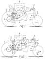
- Figs. 1-3 schematically show side views of an embodiment of the wheelchair frame according to the invention in different positions.
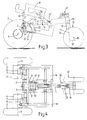
- Fig. 4 is a top view of the wheelchair frame of Figs. 1-3.
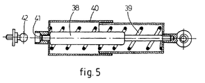
- Fig. 5 shows a cross-section of the spring means of the wheelchair frame of Fig. 1.
- Figs. 1-3 show side views of a wheelchair frame in different positions and Fig. 4 shows a top view of this wheelchair frame.
- the wheelchair frame shown comprises a central beam 1 extending in driving direction and carrying a transverse axle 2 at the front side.
- the central beam 1 and the transverse axle 2 together form a base frame part of the wheelchair frame.
- the transverse axle 2 carries at each end a front wheel 3 which can be driven by an electromotor 4.
- Each wheel 3 is rotatable around a schematically indicated axis 5 and is rotatably connected with the transverse axle 2 by means of a support arm 6 and a bush 7, wherein the axis 5 lies ahead of the transverse axle 2 as seen in driving direction.
- a coupling arm 8 is attached to each bush 7 and the coupling arm 8 is connected to a lever 10 by a pulling rod 9.
- the levers 10 are mounted at both sides on the central beam 1 rotatably around an axis 11.
- the opposite end of the levers 10 is connected with one end of a spring means 12 which at its other end is connected to the central beam 1.
- the spring means 12 forms a common spring means for the front wheels 3 lying centrally above the central beam 1 so that a very compact frame construction is obtained.
- the described construction of the wheelchair frame further shows the advantage that spaces 1a (see Figs.
- the central beam 1 carries at its backside a castor assembly 13 comprising a swivel axle 14 slidably mounted in a bush 15 which is attached to the end of the central beam 1.
- the swivel axle 14 is slidable in the bush 15 against the action of a spring 16.
- Fig. 1 shows the wheelchair frame in a not compressed position, wherein one end of the spring means 12 presses against a stop 17 of the central beam 1.
- Fig. 2 shows the wheelchair frame in a compressed position as caused by a user not shown.
- the base frame part supports a seat frame part 18 with adjustable seat angle and connected to the base frame part by means of front rods 19 and back rods 20.
- a spindle motor 21 is provided for adjusting the seat angle of the seat frame part 18.
- the seat frame part is adjusted in a relatively flat position and in Fig. 3 in the most rearwardly sloping position.
- EP-A-0 512 650 of the same applicant.
- the central castor assembly 13 provides for a very high manoeuvrability of the wheelchair frame.
- the castor assembly 13 comprises means 22 which at rotation of the swivel axle 14 from a neutral straight on position exerts a rotation force on the swivel axle 14 in the direction of the straight on position.
- These means 22 are subject of parent application EP-A-0 714 648 and for a further explination reference is made to this application.
- Fig. 5 shows a cross-section of the spring means 12.
- the spring means 12 comprises a gas spring 38 and a helical spring 39 which are mounted in the telescoping housing 40.
- This housing 40 on one side rests with a seating 41 on a ball 32 attached to the central beam 1.
- the other side of the housing 40 is rotatably connected with the levers 10.
- the gas spring 38 provides a force which is sufficient for taking the weight of the wheelchair frame and a part of the weight of the user so that the helical spring 39 can be adjusted for providing spring comfort for the user.
- the spring force of the helical spring 39 and the spring force of the spring 16 are mutually adjusted in such a manner that the central beam 1 will move substantially vertically up and down during compressing the wheelchair frame.
Landscapes
- Mechanical Engineering (AREA)
- Engineering & Computer Science (AREA)
- Health & Medical Sciences (AREA)
- General Health & Medical Sciences (AREA)
- Public Health (AREA)
- Veterinary Medicine (AREA)
- Animal Behavior & Ethology (AREA)
- Life Sciences & Earth Sciences (AREA)
- Nursing (AREA)
- Handcart (AREA)
- Automatic Cycles, And Cycles In General (AREA)
- Carriages For Children, Sleds, And Other Hand-Operated Vehicles (AREA)
- Non-Silver Salt Photosensitive Materials And Non-Silver Salt Photography (AREA)
Abstract
Description
- The invention relates to a wheelchair frame, comprising a base frame part with a plurality of wheels, said wheels being spring mounted in the base frame part and including two front wheels.
- WO-A-94 13241 discloses a wheelchair frame of the above-mentioned type, wherein only the backwheels are spring mounted in the base frame part.
- The invention aims to provide an improved wheelchair frame of the above-mentioned type.
- To this end the wheelchair frame of the invention is characterized in that each front wheel is rotatably supported by a support arm rotatably connected to a transverse axle in such a manner that the rotation axis of the front wheels lies ahead of the transverse axle as seen in forward direction.
- In this manner it is obtained that the wheelchair frame will not gallop at braking. Thereby the comfort for the user is increased and the stability of the wheelchair frame is guaranteed even at braking on downwardly sloping surfaces.
- According to a favourable embodiment the spring means comprises a gas spring and a helical spring which are mounted in a telescoping housing. Thereby a spring means is obtained wherein the action of the gas spring can be adjusted to absorb the own weight of the complete wheelchair and a part of the weight of the user, while the helical spring can be adjusted to an optimum spring comfort.
- The invention will be further explained hereinafter by reference to the drawings in which an embodiment of the wheelchair frame according to the invention is shown.
- Figs. 1-3 schematically show side views of an embodiment of the wheelchair frame according to the invention in different positions.
- Fig. 4 is a top view of the wheelchair frame of Figs. 1-3.
- Fig. 5 shows a cross-section of the spring means of the wheelchair frame of Fig. 1.
- Figs. 1-3 show side views of a wheelchair frame in different positions and Fig. 4 shows a top view of this wheelchair frame. The wheelchair frame shown comprises a
central beam 1 extending in driving direction and carrying atransverse axle 2 at the front side. Thecentral beam 1 and thetransverse axle 2 together form a base frame part of the wheelchair frame. Thetransverse axle 2 carries at each end afront wheel 3 which can be driven by anelectromotor 4. Eachwheel 3 is rotatable around a schematically indicatedaxis 5 and is rotatably connected with thetransverse axle 2 by means of asupport arm 6 and abush 7, wherein theaxis 5 lies ahead of thetransverse axle 2 as seen in driving direction. Acoupling arm 8 is attached to eachbush 7 and thecoupling arm 8 is connected to alever 10 by apulling rod 9. As shown in the top view of Fig. 4, thelevers 10 are mounted at both sides on thecentral beam 1 rotatably around anaxis 11. The opposite end of thelevers 10 is connected with one end of a spring means 12 which at its other end is connected to thecentral beam 1. In the described manner the spring means 12 forms a common spring means for thefront wheels 3 lying centrally above thecentral beam 1 so that a very compact frame construction is obtained. The described construction of the wheelchair frame further shows the advantage that spaces 1a (see Figs. 1 and 4) for the usual batteries for the power supply of theelectromotors 4 are formed at both sides of thecentral beam 1, said spaces 1a being well accessible from the sides of the wheelchair frame. Checking and maintenance of the batteries is thereby easy, wherein it is not necessary for the user to leave the wheelchair. - The
central beam 1 carries at its backside acastor assembly 13 comprising aswivel axle 14 slidably mounted in abush 15 which is attached to the end of thecentral beam 1. Theswivel axle 14 is slidable in thebush 15 against the action of aspring 16. - Fig. 1 shows the wheelchair frame in a not compressed position, wherein one end of the spring means 12 presses against a
stop 17 of thecentral beam 1. Fig. 2 shows the wheelchair frame in a compressed position as caused by a user not shown. By the suspension of thefront wheels 3 as described with the common spring means 12 it is obtained that the wheelchair frame will not gallop during braking but will rather move somewhat upwardly. This increases significantly the comfort of the uesr and also guarantees the stability of the wheelchair frame, especially during braking on a downwardly sloping surface. - In the embodiment shown the base frame part supports a
seat frame part 18 with adjustable seat angle and connected to the base frame part by means offront rods 19 andback rods 20. Aspindle motor 21 is provided for adjusting the seat angle of theseat frame part 18. In Figs. 1 and 2 the seat frame part is adjusted in a relatively flat position and in Fig. 3 in the most rearwardly sloping position. For a further explanation of the adjustable seat frame part reference is made to EP-A-0 512 650 of the same applicant. - The
central castor assembly 13 provides for a very high manoeuvrability of the wheelchair frame. In order to provide a very high straight on stability also at high driving speeds, i.e. faster than 6 km/h, thecastor assembly 13 comprises means 22 which at rotation of theswivel axle 14 from a neutral straight on position exerts a rotation force on theswivel axle 14 in the direction of the straight on position. These means 22 are subject of parent application EP-A-0 714 648 and for a further explination reference is made to this application. - Fig. 5 shows a cross-section of the spring means 12. As shown in Fig. 5, the spring means 12 comprises a
gas spring 38 and ahelical spring 39 which are mounted in thetelescoping housing 40. Thishousing 40 on one side rests with a seating 41 on a ball 32 attached to thecentral beam 1. The other side of thehousing 40 is rotatably connected with thelevers 10. Thegas spring 38 provides a force which is sufficient for taking the weight of the wheelchair frame and a part of the weight of the user so that thehelical spring 39 can be adjusted for providing spring comfort for the user. The spring force of thehelical spring 39 and the spring force of thespring 16 are mutually adjusted in such a manner that thecentral beam 1 will move substantially vertically up and down during compressing the wheelchair frame. - The inventionis not restricted to the above-described embodiment which can be varied within a number of ways within the scope of the claims.
Claims (7)
- Wheelchair frame, comprising a base frame part (1, 2) with a plurality of wheels (2, 3), said wheels being spring mounted in the base frame part and including two front wheels (3), characterized in that each front wheel (3) is rotatably supported by a support arm (6) rotatably connected to a transverse axle (2) in such a manner that the rotation axis (5) of the front wheels (3) lies ahead of the transverse axle (2) as seen in forward direction.
- Wheelchair frame according to claim 1, wherein a common spring means (12) is provided for both front wheels (3), said spring means being connected to the base frame part (1, 2) at one end and to both support arms (6) at the other end.
- Wheelchair frame according to claim 2, characterized in that the base frame part (1, 2) comprises a central beam (1) extending in the centre from the front side to the back side and carrying the transverse axle (2) at the front side, wherein the spring means (12) is mounted in the centre above the central beam and is connected to one end of levers (10) pivotably mounted at each side of the central beam, said levers being connected to a corresponding support arm (6) at their other end.
- Wheelchair frame according to claim 3, characterized in that each support arm (6) is rotatably mounted on the transverse axle (2) by means of a bush (7), wherein a coupling arm (8) is attached to each bush (7), said coupling arm being connected to the corresponding lever (10) by means of a pulling rod (9).
- Wheelchair frame according to claim 2, 3 or 4, characterized in that the spring means (12) comprises a gas spring (38) and a helical spring (39) which are mounted in a telescoping housing (40) which on one side rests with a seating (41) against a ball (42) mounted on the central beam (1) and on the other side is rotatably connected to the levers (10).
- Wheelchair frame according to anyone of the preceding claims, wherein each of the front wheels (3) can be driven by an electromotor.
- Wheelchair frame according to anyone of the preceding claims, wherein the base frame part (1, 2) carries a central castor assembly (13) at the back side.
Applications Claiming Priority (3)
| Application Number | Priority Date | Filing Date | Title |
|---|---|---|---|
| NL9402006 | 1994-11-29 | ||
| NL9402006A NL9402006A (en) | 1994-11-29 | 1994-11-29 | Wheelchair frame, as well as castor assembly. |
| EP95202638A EP0714648B1 (en) | 1994-11-29 | 1995-10-02 | Wheelchair frame and castor assembly |
Related Parent Applications (2)
| Application Number | Title | Priority Date | Filing Date |
|---|---|---|---|
| EP95202638.3 Division | 1995-10-02 | ||
| EP95202638A Division EP0714648B1 (en) | 1994-11-29 | 1995-10-02 | Wheelchair frame and castor assembly |
Publications (3)
| Publication Number | Publication Date |
|---|---|
| EP0800809A2 true EP0800809A2 (en) | 1997-10-15 |
| EP0800809A3 EP0800809A3 (en) | 1997-12-10 |
| EP0800809B1 EP0800809B1 (en) | 2001-01-17 |
Family
ID=19864952
Family Applications (2)
| Application Number | Title | Priority Date | Filing Date |
|---|---|---|---|
| EP97202024A Expired - Lifetime EP0800809B1 (en) | 1994-11-29 | 1995-10-02 | Wheelchair frame |
| EP95202638A Expired - Lifetime EP0714648B1 (en) | 1994-11-29 | 1995-10-02 | Wheelchair frame and castor assembly |
Family Applications After (1)
| Application Number | Title | Priority Date | Filing Date |
|---|---|---|---|
| EP95202638A Expired - Lifetime EP0714648B1 (en) | 1994-11-29 | 1995-10-02 | Wheelchair frame and castor assembly |
Country Status (12)
| Country | Link |
|---|---|
| US (1) | US5762155A (en) |
| EP (2) | EP0800809B1 (en) |
| JP (1) | JPH08215253A (en) |
| AT (2) | ATE162392T1 (en) |
| CA (1) | CA2164016A1 (en) |
| DE (2) | DE69501494T2 (en) |
| DK (2) | DK0714648T3 (en) |
| ES (2) | ES2155236T3 (en) |
| GR (2) | GR3026515T3 (en) |
| NL (1) | NL9402006A (en) |
| NO (1) | NO307123B1 (en) |
| PT (1) | PT800809E (en) |
Cited By (3)
| Publication number | Priority date | Publication date | Assignee | Title |
|---|---|---|---|---|
| EP0861649A2 (en) * | 1997-02-17 | 1998-09-02 | Richard Van Seenus Nederland B.V. | Wheel chair |
| NL1008418C2 (en) * | 1998-02-25 | 1999-08-26 | Aquarius Bv | Tiltable wheelchair with supporting spring element. |
| WO2012100761A1 (en) * | 2011-01-25 | 2012-08-02 | Rudolf Hupert | Frame for a compact vehicle |
Families Citing this family (46)
| Publication number | Priority date | Publication date | Assignee | Title |
|---|---|---|---|---|
| GB9423056D0 (en) * | 1994-11-16 | 1995-01-04 | Sunrise Medical Ltd | Castors, and vehicles having same |
| NL1003396C1 (en) * | 1996-06-21 | 1997-12-23 | Ligtvoet Products Bv | Wheelchair equipped with a castor wheel. |
| JPH10203459A (en) * | 1996-11-20 | 1998-08-04 | Yamaha Motor Co Ltd | Small-sized vehicle |
| GB9812933D0 (en) | 1998-06-16 | 1998-08-12 | Black & Decker Inc | Tool system |
| GB9812934D0 (en) | 1998-06-16 | 1998-08-12 | Black & Decker Inc | Adjustment mechanism |
| GB9812935D0 (en) | 1998-06-16 | 1998-08-12 | Black & Decker Inc | Interconnection mechanism |
| GB9812932D0 (en) * | 1998-06-16 | 1998-08-12 | Black & Decker Inc | Wheel mechanism |
| GB9814998D0 (en) | 1998-07-11 | 1998-09-09 | Black & Decker Inc | Wheel locking mechanism |
| US6554086B1 (en) | 2000-10-27 | 2003-04-29 | Invacare Corporation | Obstacle traversing wheelchair |
| US7018157B2 (en) * | 2001-09-20 | 2006-03-28 | Hill-Rom Services, Inc. | Powered transport apparatus for a bed |
| US7040429B2 (en) | 2001-10-10 | 2006-05-09 | Invacare Corporation | Wheelchair suspension |
| US7066290B2 (en) | 2001-10-19 | 2006-06-27 | Invacare Corp. | Wheelchair suspension having pivotal motor mount |
| US7533742B2 (en) * | 2001-10-26 | 2009-05-19 | Dane Industries, Inc. | Bed transfer system |
| CA2464783A1 (en) * | 2001-10-26 | 2003-05-01 | Daniel Johnson | Hospital bed power-assist |
| GB0214223D0 (en) | 2002-06-20 | 2002-07-31 | Mills Christopher J | Wheeled conveyance |
| US7293801B2 (en) | 2003-08-18 | 2007-11-13 | Invacare Corporation | Self-stabilizing suspension for wheeled vehicles |
| US11213441B2 (en) | 2002-10-25 | 2022-01-04 | Invacare Corporation | Suspension for wheeled vehicles |
| AU2004236214A1 (en) * | 2003-05-03 | 2004-11-18 | Dane Industries | Cart mover |
| EP1682396B1 (en) * | 2003-09-23 | 2014-03-12 | Dane Industries | Power assisted cart retriever with attenuated power output |
| US7571914B2 (en) * | 2003-10-15 | 2009-08-11 | Dane Industries, Inc. | Push-pull cart collection device and conversion assembly |
| WO2005037624A2 (en) * | 2003-10-15 | 2005-04-28 | Dane Industries | Cart coupler assembly for cart collection machines |
| US7870917B2 (en) * | 2004-10-25 | 2011-01-18 | Sanyo Electric Co., Ltd. | Drive device for electrically movable vehicles and electric wheelchair having same |
| US20070289787A1 (en) * | 2005-02-25 | 2007-12-20 | Dane Industries, Inc. | Wheelchair transporter |
| EP1853478A2 (en) * | 2005-02-25 | 2007-11-14 | Dane Industries, Inc. | Wheelchair transporter |
| US7857342B2 (en) * | 2005-06-07 | 2010-12-28 | Dane Technologies, Inc. | Hitch assembly |
| US20070013157A1 (en) * | 2005-07-18 | 2007-01-18 | Wiff James W | Dual hitch assembly |
| US20070051541A1 (en) * | 2005-09-07 | 2007-03-08 | Delphi Technologies, Inc. | Method of castor management |
| US7686145B2 (en) * | 2005-09-21 | 2010-03-30 | Sanyo Electric Co., Ltd. | Drive device for electrically movable vehicles and electric wheelchair having same |
| EP1943995A1 (en) | 2007-01-12 | 2008-07-16 | Invacare International Sàrl | A wheeled conveyance with suspension arms for wheels |
| DE602008004311D1 (en) * | 2007-02-08 | 2011-02-17 | Invacare Corp | WHEELCHAIR SUSPENSION |
| US8910975B2 (en) | 2007-02-14 | 2014-12-16 | Invacare Corporation | Wheelchair with suspension |
| DE102007014680B4 (en) * | 2007-03-27 | 2009-06-18 | Pihsiang Machinery Manufacturing Co., Ltd., Sinfong | Folding, electric wheelchair |
| AU2009217231B2 (en) * | 2008-02-21 | 2015-02-12 | Noah No. 1 Pty Ltd | A castor wheel |
| US8360459B2 (en) * | 2008-04-11 | 2013-01-29 | Dane Technologies, Inc. | Cart transporting apparatus |
| US20100038880A1 (en) * | 2008-08-15 | 2010-02-18 | Bagg Christian Peter Edward | Modular and/or configurable wheelchair apparatus |
| US8684373B2 (en) * | 2008-09-23 | 2014-04-01 | Dane Technologies, Inc. | Cart moving machine |
| EP3238682A3 (en) | 2009-10-09 | 2018-01-10 | Invacare Corporation | Wheelchair suspension with opposite movement of anti-tip arms |
| US9010771B2 (en) | 2009-11-10 | 2015-04-21 | Dane Technologies, Inc. | Utility machine with dual-mode steering |
| US8851214B2 (en) * | 2010-07-15 | 2014-10-07 | Permobil Ab | Electric mid-wheel drive wheelchair |
| US9308143B2 (en) | 2012-02-15 | 2016-04-12 | Invacare Corporation | Wheelchair suspension |
| WO2015095156A1 (en) * | 2013-12-16 | 2015-06-25 | Mulhern James P | Elevated height wheelchair |
| US9956473B2 (en) * | 2015-06-19 | 2018-05-01 | Kevin Chiu | Transportation vehicle |
| EP3419579A4 (en) | 2016-02-27 | 2020-03-18 | Pride Mobility Products Corporation | Adjustable height wheelchair |
| CN106314031B (en) * | 2016-09-30 | 2018-10-26 | 宁波介量机器人技术有限公司 | A kind of force servo electric drive system |
| WO2018183347A1 (en) | 2017-03-27 | 2018-10-04 | Pacific Cycle, Llc | Interactive ride-on toy apparatus |
| EP4110257A4 (en) | 2020-02-25 | 2024-03-06 | Invacare Corporation | Wheelchair and suspension systems |
Citations (6)
| Publication number | Priority date | Publication date | Assignee | Title |
|---|---|---|---|---|
| US2493817A (en) * | 1946-07-01 | 1950-01-10 | Terence G Hare | Powered three-wheeled vehicle |
| DE3414204A1 (en) * | 1984-04-14 | 1985-10-24 | Horst 4970 Bad Oeynhausen Lindenkamp | Small vehicle, in particular for disabled persons |
| US4714126A (en) * | 1982-12-28 | 1987-12-22 | Honda Giken Kogyo Kabushiki Kaisha | Four-wheel drive vehicle |
| DE9012188U1 (en) * | 1990-08-24 | 1990-10-25 | MEYRA Wilhelm Meyer GmbH & Co KG, 4925 Kalletal | wheelchair |
| WO1994015567A1 (en) * | 1993-01-13 | 1994-07-21 | Ligtvoet Products B.V. | Wheelchair |
| WO1996015000A1 (en) * | 1994-11-16 | 1996-05-23 | Sunrise Medical Limited | Vehicle having castors |
Family Cites Families (17)
| Publication number | Priority date | Publication date | Assignee | Title |
|---|---|---|---|---|
| US940783A (en) * | 1908-12-21 | 1909-11-23 | Seth J Buckland | Front-fork equalizer. |
| GB549773A (en) * | 1941-03-03 | 1942-12-07 | Rubery Owen Messier Ltd | Improvements in or relating to damping apparatus for swivelling wheels of aircraft and other vehicles |
| US2620235A (en) * | 1947-11-12 | 1952-12-02 | Dunlop Rubber Co | Nose or tail wheels of aircraft |
| US2482961A (en) * | 1948-01-16 | 1949-09-27 | Arthur E Bishop | Friction device for damping shimmy in caster wheels |
| FR1120072A (en) * | 1954-10-29 | 1956-06-29 | Steering rectifier, applicable to two or three wheel vehicles | |
| US3064744A (en) * | 1960-07-11 | 1962-11-20 | Everest & Jennings | Self-propelled wheel chair |
| US3990716A (en) * | 1975-09-02 | 1976-11-09 | Dows Parker G | Resilient steering stabilizer |
| US4280246A (en) * | 1980-01-10 | 1981-07-28 | Roll-Rite Corp. | Self-steering caster |
| FR2479104A1 (en) * | 1980-03-28 | 1981-10-02 | Saxby | DEVICE FOR AUTOMATICALLY RECALLING THE SWIVEL WHEELS OF A MANUAL TRUCK IN A PREDETERMINED DIRECTION |
| US4614246A (en) * | 1985-07-15 | 1986-09-30 | Masse James H | Powered wheel chair |
| SE465015B (en) * | 1987-06-22 | 1991-07-15 | Inm Industriteknik Ab | ELECTRICALLY DISABLED VEHICLE CARES IN SPECIAL CHILD |
| US5028064A (en) * | 1989-02-10 | 1991-07-02 | Johnson John W | Racing wheelchair |
| US5222567A (en) * | 1991-04-26 | 1993-06-29 | Genus Inc. | Power assist device for a wheelchair |
| NL9202183A (en) * | 1992-12-17 | 1994-07-18 | Seenus Nl Bv R Van | Wheelchair. |
| GB2275029B (en) * | 1993-02-12 | 1996-06-05 | Stephen John Rose | Improvements in and relating to wheelchairs |
| US5275248A (en) * | 1993-03-11 | 1994-01-04 | Finch Thomas E | Power operated wheelchair |
| GB9319701D0 (en) * | 1993-09-24 | 1993-11-10 | Multicontrol Ltd | Castors |
-
1994
- 1994-11-29 NL NL9402006A patent/NL9402006A/en not_active Application Discontinuation
-
1995
- 1995-10-02 DE DE69501494T patent/DE69501494T2/en not_active Expired - Fee Related
- 1995-10-02 EP EP97202024A patent/EP0800809B1/en not_active Expired - Lifetime
- 1995-10-02 EP EP95202638A patent/EP0714648B1/en not_active Expired - Lifetime
- 1995-10-02 AT AT95202638T patent/ATE162392T1/en not_active IP Right Cessation
- 1995-10-02 ES ES97202024T patent/ES2155236T3/en not_active Expired - Lifetime
- 1995-10-02 PT PT97202024T patent/PT800809E/en unknown
- 1995-10-02 ES ES95202638T patent/ES2113153T3/en not_active Expired - Lifetime
- 1995-10-02 AT AT97202024T patent/ATE198701T1/en not_active IP Right Cessation
- 1995-10-02 DE DE69519943T patent/DE69519943T2/en not_active Expired - Fee Related
- 1995-10-02 DK DK95202638T patent/DK0714648T3/en active
- 1995-10-02 DK DK97202024T patent/DK0800809T3/en active
- 1995-10-16 US US08/543,267 patent/US5762155A/en not_active Expired - Fee Related
- 1995-10-27 NO NO954303A patent/NO307123B1/en not_active IP Right Cessation
- 1995-11-22 JP JP7304137A patent/JPH08215253A/en active Pending
- 1995-11-29 CA CA002164016A patent/CA2164016A1/en not_active Abandoned
-
1998
- 1998-04-03 GR GR980400699T patent/GR3026515T3/en unknown
-
2001
- 2001-04-12 GR GR20010400607T patent/GR3035755T3/en not_active IP Right Cessation
Patent Citations (6)
| Publication number | Priority date | Publication date | Assignee | Title |
|---|---|---|---|---|
| US2493817A (en) * | 1946-07-01 | 1950-01-10 | Terence G Hare | Powered three-wheeled vehicle |
| US4714126A (en) * | 1982-12-28 | 1987-12-22 | Honda Giken Kogyo Kabushiki Kaisha | Four-wheel drive vehicle |
| DE3414204A1 (en) * | 1984-04-14 | 1985-10-24 | Horst 4970 Bad Oeynhausen Lindenkamp | Small vehicle, in particular for disabled persons |
| DE9012188U1 (en) * | 1990-08-24 | 1990-10-25 | MEYRA Wilhelm Meyer GmbH & Co KG, 4925 Kalletal | wheelchair |
| WO1994015567A1 (en) * | 1993-01-13 | 1994-07-21 | Ligtvoet Products B.V. | Wheelchair |
| WO1996015000A1 (en) * | 1994-11-16 | 1996-05-23 | Sunrise Medical Limited | Vehicle having castors |
Non-Patent Citations (1)
| Title |
|---|
| "GAAF GEBRUIKSVRIENDELIJK KARRETJE" POLYTECHNISCH TIJDSCHRIFT, WERKTUIGBOUW, vol. 48, no. 8, page 21 XP000384929 * |
Cited By (5)
| Publication number | Priority date | Publication date | Assignee | Title |
|---|---|---|---|---|
| EP0861649A2 (en) * | 1997-02-17 | 1998-09-02 | Richard Van Seenus Nederland B.V. | Wheel chair |
| EP0861649A3 (en) * | 1997-02-17 | 1999-06-23 | Richard Van Seenus Nederland B.V. | Wheel chair |
| NL1008418C2 (en) * | 1998-02-25 | 1999-08-26 | Aquarius Bv | Tiltable wheelchair with supporting spring element. |
| EP0945114A1 (en) * | 1998-02-25 | 1999-09-29 | Aquarius B.V. | Tiltable wheelchair having a supporting spring member |
| WO2012100761A1 (en) * | 2011-01-25 | 2012-08-02 | Rudolf Hupert | Frame for a compact vehicle |
Also Published As
| Publication number | Publication date |
|---|---|
| EP0714648B1 (en) | 1998-01-21 |
| DE69519943D1 (en) | 2001-02-22 |
| EP0714648A1 (en) | 1996-06-05 |
| EP0800809B1 (en) | 2001-01-17 |
| PT800809E (en) | 2001-07-31 |
| NL9402006A (en) | 1996-07-01 |
| DK0800809T3 (en) | 2001-06-18 |
| ATE162392T1 (en) | 1998-02-15 |
| NO307123B1 (en) | 2000-02-14 |
| JPH08215253A (en) | 1996-08-27 |
| ATE198701T1 (en) | 2001-02-15 |
| EP0800809A3 (en) | 1997-12-10 |
| DK0714648T3 (en) | 1998-09-21 |
| NO954303L (en) | 1996-05-30 |
| ES2113153T3 (en) | 1998-04-16 |
| DE69501494T2 (en) | 1998-06-25 |
| CA2164016A1 (en) | 1996-05-30 |
| DE69501494D1 (en) | 1998-02-26 |
| ES2155236T3 (en) | 2001-05-01 |
| NO954303D0 (en) | 1995-10-27 |
| DE69519943T2 (en) | 2001-08-16 |
| GR3035755T3 (en) | 2001-07-31 |
| US5762155A (en) | 1998-06-09 |
| GR3026515T3 (en) | 1998-07-31 |
Similar Documents
| Publication | Publication Date | Title |
|---|---|---|
| EP0800809A2 (en) | Wheelchair frame | |
| CA2209174C (en) | Tilt wheelchair with center of gravity compensation | |
| US7104346B2 (en) | Power wheelchair | |
| US7490683B2 (en) | Curb-climbing power wheelchair | |
| EP0445171B1 (en) | A wheelchair with a six-wheel chassis | |
| EP0677285B1 (en) | Powered wheelchair with adjustable center of gravity and independent suspension | |
| EP2101704B1 (en) | A wheelchair with suspension arms for wheels | |
| US5121806A (en) | Power wheelchair with torsional stability system | |
| US9149398B2 (en) | Obstacle traversing wheelchair | |
| EP0971671B1 (en) | Wheelchair comprising a tiltable chair | |
| US7484746B2 (en) | Wheeled conveyance | |
| US4513832A (en) | Wheeled chassis | |
| US8851214B2 (en) | Electric mid-wheel drive wheelchair | |
| US5564512A (en) | Wheelchair | |
| CA2254372A1 (en) | Motorized wheelchair | |
| WO1994015567A1 (en) | Wheelchair | |
| GB2275029A (en) | Wheelchairs | |
| EP0282118A1 (en) | Wheelchair | |
| EP0841884A1 (en) | Wheelchair and device for enabling the conversion of a chair with castors into a wheelchair | |
| WO2001089441A2 (en) | Wheelchair | |
| JP2521191Y2 (en) | Grounding structure of reel mower |
Legal Events
| Date | Code | Title | Description |
|---|---|---|---|
| PUAI | Public reference made under article 153(3) epc to a published international application that has entered the european phase |
Free format text: ORIGINAL CODE: 0009012 |
|
| AC | Divisional application: reference to earlier application |
Ref document number: 714648 Country of ref document: EP |
|
| AK | Designated contracting states |
Kind code of ref document: A2 Designated state(s): AT BE CH DE DK ES FR GB GR IE IT LI LU NL PT SE |
|
| PUAL | Search report despatched |
Free format text: ORIGINAL CODE: 0009013 |
|
| AK | Designated contracting states |
Kind code of ref document: A3 Designated state(s): AT BE CH DE DK ES FR GB GR IE IT LI LU NL PT SE |
|
| 17P | Request for examination filed |
Effective date: 19980610 |
|
| 17Q | First examination report despatched |
Effective date: 19990305 |
|
| GRAG | Despatch of communication of intention to grant |
Free format text: ORIGINAL CODE: EPIDOS AGRA |
|
| GRAG | Despatch of communication of intention to grant |
Free format text: ORIGINAL CODE: EPIDOS AGRA |
|
| GRAH | Despatch of communication of intention to grant a patent |
Free format text: ORIGINAL CODE: EPIDOS IGRA |
|
| 17Q | First examination report despatched |
Effective date: 19990305 |
|
| GRAH | Despatch of communication of intention to grant a patent |
Free format text: ORIGINAL CODE: EPIDOS IGRA |
|
| GRAA | (expected) grant |
Free format text: ORIGINAL CODE: 0009210 |
|
| AC | Divisional application: reference to earlier application |
Ref document number: 714648 Country of ref document: EP |
|
| AK | Designated contracting states |
Kind code of ref document: B1 Designated state(s): AT BE CH DE DK ES FR GB GR IE IT LI LU NL PT SE |
|
| REF | Corresponds to: |
Ref document number: 198701 Country of ref document: AT Date of ref document: 20010215 Kind code of ref document: T |
|
| REG | Reference to a national code |
Ref country code: CH Ref legal event code: EP |
|
| REG | Reference to a national code |
Ref country code: IE Ref legal event code: FG4D |
|
| REF | Corresponds to: |
Ref document number: 69519943 Country of ref document: DE Date of ref document: 20010222 |
|
| ITF | It: translation for a ep patent filed | ||
| REG | Reference to a national code |
Ref country code: CH Ref legal event code: NV Representative=s name: OK PAT AG |
|
| REG | Reference to a national code |
Ref country code: ES Ref legal event code: FG2A Ref document number: 2155236 Country of ref document: ES Kind code of ref document: T3 |
|
| ET | Fr: translation filed | ||
| REG | Reference to a national code |
Ref country code: DK Ref legal event code: T3 |
|
| REG | Reference to a national code |
Ref country code: PT Ref legal event code: SC4A Free format text: AVAILABILITY OF NATIONAL TRANSLATION Effective date: 20010416 |
|
| PGFP | Annual fee paid to national office [announced via postgrant information from national office to epo] |
Ref country code: PT Payment date: 20011003 Year of fee payment: 7 Ref country code: IE Payment date: 20011003 Year of fee payment: 7 Ref country code: GB Payment date: 20011003 Year of fee payment: 7 |
|
| PGFP | Annual fee paid to national office [announced via postgrant information from national office to epo] |
Ref country code: ES Payment date: 20011004 Year of fee payment: 7 |
|
| PGFP | Annual fee paid to national office [announced via postgrant information from national office to epo] |
Ref country code: CH Payment date: 20011005 Year of fee payment: 7 |
|
| PGFP | Annual fee paid to national office [announced via postgrant information from national office to epo] |
Ref country code: GR Payment date: 20011010 Year of fee payment: 7 |
|
| PGFP | Annual fee paid to national office [announced via postgrant information from national office to epo] |
Ref country code: DK Payment date: 20011023 Year of fee payment: 7 |
|
| PGFP | Annual fee paid to national office [announced via postgrant information from national office to epo] |
Ref country code: LU Payment date: 20011030 Year of fee payment: 7 Ref country code: AT Payment date: 20011030 Year of fee payment: 7 |
|
| PGFP | Annual fee paid to national office [announced via postgrant information from national office to epo] |
Ref country code: FR Payment date: 20011031 Year of fee payment: 7 Ref country code: BE Payment date: 20011031 Year of fee payment: 7 |
|
| PLBE | No opposition filed within time limit |
Free format text: ORIGINAL CODE: 0009261 |
|
| STAA | Information on the status of an ep patent application or granted ep patent |
Free format text: STATUS: NO OPPOSITION FILED WITHIN TIME LIMIT |
|
| REG | Reference to a national code |
Ref country code: GB Ref legal event code: IF02 |
|
| 26N | No opposition filed | ||
| PG25 | Lapsed in a contracting state [announced via postgrant information from national office to epo] |
Ref country code: LU Free format text: LAPSE BECAUSE OF NON-PAYMENT OF DUE FEES Effective date: 20021002 Ref country code: IE Free format text: LAPSE BECAUSE OF NON-PAYMENT OF DUE FEES Effective date: 20021002 Ref country code: GB Free format text: LAPSE BECAUSE OF NON-PAYMENT OF DUE FEES Effective date: 20021002 Ref country code: AT Free format text: LAPSE BECAUSE OF NON-PAYMENT OF DUE FEES Effective date: 20021002 |
|
| PG25 | Lapsed in a contracting state [announced via postgrant information from national office to epo] |
Ref country code: ES Free format text: LAPSE BECAUSE OF NON-PAYMENT OF DUE FEES Effective date: 20021003 |
|
| PGFP | Annual fee paid to national office [announced via postgrant information from national office to epo] |
Ref country code: SE Payment date: 20021009 Year of fee payment: 8 |
|
| PG25 | Lapsed in a contracting state [announced via postgrant information from national office to epo] |
Ref country code: LI Free format text: LAPSE BECAUSE OF NON-PAYMENT OF DUE FEES Effective date: 20021031 Ref country code: DK Free format text: LAPSE BECAUSE OF NON-PAYMENT OF DUE FEES Effective date: 20021031 Ref country code: CH Free format text: LAPSE BECAUSE OF NON-PAYMENT OF DUE FEES Effective date: 20021031 Ref country code: BE Free format text: LAPSE BECAUSE OF NON-PAYMENT OF DUE FEES Effective date: 20021031 |
|
| PGFP | Annual fee paid to national office [announced via postgrant information from national office to epo] |
Ref country code: NL Payment date: 20021031 Year of fee payment: 8 |
|
| PGFP | Annual fee paid to national office [announced via postgrant information from national office to epo] |
Ref country code: DE Payment date: 20021230 Year of fee payment: 8 |
|
| BERE | Be: lapsed |
Owner name: RICHARD *VAN SEENUS NEDERLAND B.V. Effective date: 20021031 |
|
| PG25 | Lapsed in a contracting state [announced via postgrant information from national office to epo] |
Ref country code: PT Free format text: LAPSE BECAUSE OF NON-PAYMENT OF DUE FEES Effective date: 20030430 |
|
| PG25 | Lapsed in a contracting state [announced via postgrant information from national office to epo] |
Ref country code: GR Free format text: LAPSE BECAUSE OF NON-PAYMENT OF DUE FEES Effective date: 20030506 |
|
| GBPC | Gb: european patent ceased through non-payment of renewal fee |
Effective date: 20021002 |
|
| REG | Reference to a national code |
Ref country code: CH Ref legal event code: PL |
|
| REG | Reference to a national code |
Ref country code: DK Ref legal event code: EBP |
|
| PG25 | Lapsed in a contracting state [announced via postgrant information from national office to epo] |
Ref country code: FR Free format text: LAPSE BECAUSE OF NON-PAYMENT OF DUE FEES Effective date: 20030630 |
|
| REG | Reference to a national code |
Ref country code: IE Ref legal event code: MM4A |
|
| REG | Reference to a national code |
Ref country code: FR Ref legal event code: ST |
|
| PG25 | Lapsed in a contracting state [announced via postgrant information from national office to epo] |
Ref country code: SE Free format text: LAPSE BECAUSE OF NON-PAYMENT OF DUE FEES Effective date: 20031003 |
|
| PG25 | Lapsed in a contracting state [announced via postgrant information from national office to epo] |
Ref country code: NL Free format text: LAPSE BECAUSE OF NON-PAYMENT OF DUE FEES Effective date: 20040501 Ref country code: DE Free format text: LAPSE BECAUSE OF NON-PAYMENT OF DUE FEES Effective date: 20040501 |
|
| REG | Reference to a national code |
Ref country code: ES Ref legal event code: FD2A Effective date: 20031112 |
|
| EUG | Se: european patent has lapsed | ||
| NLV4 | Nl: lapsed or anulled due to non-payment of the annual fee |
Effective date: 20040501 |
|
| PG25 | Lapsed in a contracting state [announced via postgrant information from national office to epo] |
Ref country code: IT Free format text: LAPSE BECAUSE OF NON-PAYMENT OF DUE FEES Effective date: 20051002 |