EP0800619B1 - Procede de refroidissement du refrigerant d'une turbine a gaz et dispositif de mise en oeuvre dudit procede - Google Patents
Procede de refroidissement du refrigerant d'une turbine a gaz et dispositif de mise en oeuvre dudit procede Download PDFInfo
- Publication number
- EP0800619B1 EP0800619B1 EP95940958A EP95940958A EP0800619B1 EP 0800619 B1 EP0800619 B1 EP 0800619B1 EP 95940958 A EP95940958 A EP 95940958A EP 95940958 A EP95940958 A EP 95940958A EP 0800619 B1 EP0800619 B1 EP 0800619B1
- Authority
- EP
- European Patent Office
- Prior art keywords
- steam
- coolant
- gas
- gas turbine
- steam drum
- Prior art date
- Legal status (The legal status is an assumption and is not a legal conclusion. Google has not performed a legal analysis and makes no representation as to the accuracy of the status listed.)
- Expired - Lifetime
Links
- 238000001816 cooling Methods 0.000 title claims description 39
- 239000002826 coolant Substances 0.000 title claims description 37
- 238000000034 method Methods 0.000 title claims description 11
- XLYOFNOQVPJJNP-UHFFFAOYSA-N water Substances O XLYOFNOQVPJJNP-UHFFFAOYSA-N 0.000 claims description 38
- 239000007789 gas Substances 0.000 description 66
- 239000002609 medium Substances 0.000 description 20
- 238000002347 injection Methods 0.000 description 5
- 239000007924 injection Substances 0.000 description 5
- 239000000203 mixture Substances 0.000 description 5
- 230000000694 effects Effects 0.000 description 4
- 238000001704 evaporation Methods 0.000 description 3
- 230000008020 evaporation Effects 0.000 description 3
- UGFAIRIUMAVXCW-UHFFFAOYSA-N Carbon monoxide Chemical compound [O+]#[C-] UGFAIRIUMAVXCW-UHFFFAOYSA-N 0.000 description 2
- 239000003546 flue gas Substances 0.000 description 2
- JEGUKCSWCFPDGT-UHFFFAOYSA-N h2o hydrate Chemical compound O.O JEGUKCSWCFPDGT-UHFFFAOYSA-N 0.000 description 2
- 238000010438 heat treatment Methods 0.000 description 2
- 239000000463 material Substances 0.000 description 2
- 238000011084 recovery Methods 0.000 description 2
- 238000005422 blasting Methods 0.000 description 1
- 239000003990 capacitor Substances 0.000 description 1
- 238000002485 combustion reaction Methods 0.000 description 1
- 238000013021 overheating Methods 0.000 description 1
- 239000003380 propellant Substances 0.000 description 1
- 238000000926 separation method Methods 0.000 description 1
- 238000009834 vaporization Methods 0.000 description 1
- 230000008016 vaporization Effects 0.000 description 1
Images
Classifications
-
- F—MECHANICAL ENGINEERING; LIGHTING; HEATING; WEAPONS; BLASTING
- F01—MACHINES OR ENGINES IN GENERAL; ENGINE PLANTS IN GENERAL; STEAM ENGINES
- F01K—STEAM ENGINE PLANTS; STEAM ACCUMULATORS; ENGINE PLANTS NOT OTHERWISE PROVIDED FOR; ENGINES USING SPECIAL WORKING FLUIDS OR CYCLES
- F01K23/00—Plants characterised by more than one engine delivering power external to the plant, the engines being driven by different fluids
- F01K23/02—Plants characterised by more than one engine delivering power external to the plant, the engines being driven by different fluids the engine cycles being thermally coupled
- F01K23/06—Plants characterised by more than one engine delivering power external to the plant, the engines being driven by different fluids the engine cycles being thermally coupled combustion heat from one cycle heating the fluid in another cycle
- F01K23/10—Plants characterised by more than one engine delivering power external to the plant, the engines being driven by different fluids the engine cycles being thermally coupled combustion heat from one cycle heating the fluid in another cycle with exhaust fluid of one cycle heating the fluid in another cycle
-
- F—MECHANICAL ENGINEERING; LIGHTING; HEATING; WEAPONS; BLASTING
- F02—COMBUSTION ENGINES; HOT-GAS OR COMBUSTION-PRODUCT ENGINE PLANTS
- F02C—GAS-TURBINE PLANTS; AIR INTAKES FOR JET-PROPULSION PLANTS; CONTROLLING FUEL SUPPLY IN AIR-BREATHING JET-PROPULSION PLANTS
- F02C7/00—Features, components parts, details or accessories, not provided for in, or of interest apart form groups F02C1/00 - F02C6/00; Air intakes for jet-propulsion plants
- F02C7/12—Cooling of plants
- F02C7/16—Cooling of plants characterised by cooling medium
- F02C7/18—Cooling of plants characterised by cooling medium the medium being gaseous, e.g. air
- F02C7/185—Cooling means for reducing the temperature of the cooling air or gas
-
- Y—GENERAL TAGGING OF NEW TECHNOLOGICAL DEVELOPMENTS; GENERAL TAGGING OF CROSS-SECTIONAL TECHNOLOGIES SPANNING OVER SEVERAL SECTIONS OF THE IPC; TECHNICAL SUBJECTS COVERED BY FORMER USPC CROSS-REFERENCE ART COLLECTIONS [XRACs] AND DIGESTS
- Y02—TECHNOLOGIES OR APPLICATIONS FOR MITIGATION OR ADAPTATION AGAINST CLIMATE CHANGE
- Y02E—REDUCTION OF GREENHOUSE GAS [GHG] EMISSIONS, RELATED TO ENERGY GENERATION, TRANSMISSION OR DISTRIBUTION
- Y02E20/00—Combustion technologies with mitigation potential
- Y02E20/16—Combined cycle power plant [CCPP], or combined cycle gas turbine [CCGT]
Definitions
- the invention relates to a method for cooling the Coolant of a gas turbine of a gas and steam turbine plant with a first evaporator circuit comprising a steam drum. It continues to focus on a device for cooling the coolant of a gas turbine of a gas and steam turbine plant for carrying out such Procedure.
- a gas and steam turbine plant is typically used for generation electrical energy used.
- An in an evaporator circuit of the steam turbine system Working medium usually a water-water / steam mixture, evaporated in an evaporator, the steam generated thereby is used for energy generation.
- the Evaporator circuit can also be a forced circulation, in which the Circulation of the working medium by a circulating pump is guaranteed, the working medium in the evaporator also evaporated at least partially.
- Natural circulation as well as forced circulation is the water-water / steam mixture from the evaporator into the Evaporator circuit fed switched steam drum. In The steam drum separates water and steam, whereby from the steam drum is fed the water again to the evaporator becomes.
- the forced circulation or the forced circulation principle application is used to increase performance the gas turbine and thus to achieve the highest possible Efficiency of such a gas and steam turbine plant a particularly high temperature of the propellant gas at the inlet of the Gas turbine aimed for example from 1000 to 1200 ° C.
- a such a high turbine inlet temperature brings however Material problems with themselves, especially with regard to the Heat resistance of the turbine blades.
- Such a device for cooling the cooling air Gas turbine is for a certain temperature difference between the water taken from the steam drum and the cooling air designed. For example, increases due to peak load operation or by taking process steam, the pressure in the evaporator circuit and thus the water temperature in the steam drum increases, so does the temperature of the cooling air Gas turbine. This means that the cooling air is practically cooled to the temperature required to cool the gas turbine no longer guarantees what a gas turbine failure can cause.
- the invention is therefore based on the object of a method for cooling the coolant of a gas turbine of a gas and Steam turbine system with a steam drum Evaporator circuit to specify, in the particularly simple Sufficient cooling under all operating conditions the gas turbine is guaranteed. This is supposed to be with a particularly suitable device can be achieved.
- this object is achieved by that for a gas and steam turbine plant above type, in which the coolant of the gas turbine by exchanging heat with one in one connected to the steam drum second or separate evaporator circuit circulating Medium is cooled, the temperature of the coolant of the gas turbine a variation of the parameters determining the heat exchanger, especially by varying the temperature of the separately Evaporator circuit circulating medium, is set.
- the coolant temperature is set by Injection of condensate into the separate evaporator circuit.
- the cooling of the coolant of the gas turbine is therefore not only for a certain temperature difference between the coolant the gas turbine and the coolant cooling the coolant designed.
- the invention is based on the consideration that by variation parameters influencing the heat exchange, in particular by varying the temperature of the separately Evaporator circuit circulating medium, the cooling of the Coolant of the gas turbine to any operating state the gas and steam turbine plant can be adapted.
- the temperature of the gas turbine coolant can be independent on the temperature difference between the coolant and the circulating medium, on one for cooling the Gas turbine be kept of sufficient value.
- the separate evaporator circuit can be a natural circulation Forced circulation or a forced run, being in each Case the coolant of the gas turbine extracted by cooling Warm the steam generation process of the gas and steam turbine plant can be supplied.
- one Gas turbine of a gas and steam turbine plant with one Evaporator circuit having a steam drum is said Task solved by a secondary side with the coolant supply heat exchanger connected to the gas turbine on the primary side via a separate evaporator circuit Steam drum is connected.
- a secondary side with the coolant supply heat exchanger connected to the gas turbine on the primary side via a separate evaporator circuit Steam drum is connected.
- Steam drum is connected.
- For injecting condensate in the separate evaporator circuit and thus for variation the temperature of the coolant that cools the gas turbine Coolant is an injector connection between one Feed water supply to the steam drum and the separate one Evaporator circuit provided.
- the injector connection can advantageously be throttled and / or lockable.
- To drain excess water out of the steam drum is the steam drum with the feed water tank the gas and steam turbine plant expediently lockable connected.
- the advantages achieved with the invention are in particular in that by cooling the coolant of the gas turbine by exchanging heat with one in one to the steam drum connected separate evaporator circuit circulating medium as well as the possible feeding of Condensate in the separate evaporator circuit for cooling of the coolant of the gas turbine in all operating states of the Gas and steam turbine plant, especially in peak load operation, is ensured.
- Such a device for cooling the coolant of the gas turbine can with respect Efficiency criteria for the nominal load operation of the gas and Steam turbine system can be optimized, without a uneconomical oversizing for peak load operation necessary is.
- Cooling the coolant of the gas turbine, especially in peak load operation, is about the possible Temperature setting of the in the separate evaporator circuit circulating medium ensured by the condensate injection, so that such a gas and steam turbine plant can be operated particularly flexibly and inexpensively.
- a targeted forced flow of the circulating in the separate evaporator circuit Medium possible through the heat exchanger, which reduces the start-up behavior of the evaporator system is influenced favorably.
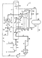
- FIG. 1 An embodiment of the invention is based on a Drawing explained in more detail.
- the figure shows schematically a gas and steam turbine system with a device for Cooling the coolant for the gas turbine.
- the gas and steam turbine plant shown schematically in the figure 1 comprises a gas turbine 2 with gas downstream Heat recovery steam generator 4, the heating surfaces in one Water-steam circuit 6 of a steam turbine 8 switched are.
- the heating surfaces are a low pressure preheater 10, a low pressure evaporator 12 and a low pressure superheater 14.
- the steam turbine 8 is followed by a capacitor 16 which via a condensate pump 18 and a feed water supply 20 is connected to the low pressure preheater 10.
- This is on the output side via a supply line which can be shut off with a valve 22 24a with a feed water tank 26 and, in parallel to line 24a, via a valve 28 which can be shut off Line 24b with a steam drum or a water-steam separation container 30 connected.
- a feed line 32 for supplying feed water in a - not shown - high pressure evaporator area the gas and steam turbine system 1 arranged.
- the steam drum 30 is on the steam and water side with the in a first evaporator circuit 34 switched low pressure evaporator 12 connected.
- the evaporator circuit 34 is there a natural circulation. But it can also be a forced circulation or a Be forced pass.
- the steam drum 30 is on the steam outlet side via a line 36 connected to the low pressure superheater 16, which in turn the output side via a line 38 to the steam turbine 8 is connected.
- the steam drum 30 is also over a lockable with a valve 39 drain line 40 to the Feed water tank 26 connected.
- a second or separate evaporator circuit is attached to the steam drum 30 41 connected.
- the separate evaporator circuit 41 is the primary input of a heat exchanger 42 switched.
- the separate evaporator circuit 41 is a natural circulation, which is also a forced circulation or can be a forced run.
- the heat exchanger 42 is on the secondary side into a cooling air line opening into the gas turbine 2 43 switched. In the cooling air line 43 exists one at the points labeled a and b Connection to the gas turbine 2.
- the feed water supply 20 is via an injector connection 44, which can be shut off with a valve 45 connecting line 46 and an injector 48 includes, with the separate Evaporator circuit 41 connected.
- the injector 48 points thereby an injection nozzle 50.
- Useful steam N removed from the steam drum 30 is fed to the low-pressure superheater 14 via the line 36 and overheated there and then via line 38 of the Steam turbine 8 fed, in which he relaxes.
- the relaxed one Steam is fed into the condenser 16 and condensed there.
- the resulting condensate is discharged through the condensate pump 18 in the feed water supply 20 to the low pressure preheater 10 promoted and from there via line 24a the feed water tank 26 or via line 24b Steam drum 30 supplied.
- cooling air L is supplied to it via line 43.
- the temperature of the supplied cooling air L must not exceed a maximum value. This requires cooling of the cooling air L, which is achieved by heat exchange in the heat exchanger 42.
- the heat exchange in the heat exchanger 42 takes place with water W circulating in the separate evaporator circuit 41 connected to the steam drum 30.
- the parameters determining the heat exchange of the cooling air L with the water W can be varied.
- the mass flow of the water W circulating in the separate evaporator circuit 41 can be throttled and adjusted.
- the temperature T W of the medium W circulating in the separate evaporator circuit 41 is adjustable.
- condensate K is preferably removed from the feed water supply 20 via the connecting line 46 and the injector 48 and fed into the separate evaporator circuit 41.
- the condensate K removed in this way is significantly colder at a temperature T k of approximately 40 ° C. than the water W flowing from the steam drum 30 into the separate evaporator circuit 41 with a temperature T W of approximately 150 ° C.
- the temperature T g of the cooling medium G fed to the heat exchanger 42, the mixture of condensate K and water W is determined by the variable amount of the valve 45 supplied condensate K adjustable.
- the temperature of the cooling air L of the gas turbine 2 cooled by the heat exchange in the heat exchanger 42 can thus also be set. During peak load operation of the gas and steam turbine system 1, adequate cooling of the cooling air L of the gas turbine 2 is ensured by increasing the amount of condensate K injected into the separate evaporator circuit 41.
Landscapes
- Engineering & Computer Science (AREA)
- Chemical & Material Sciences (AREA)
- Combustion & Propulsion (AREA)
- Mechanical Engineering (AREA)
- General Engineering & Computer Science (AREA)
- Engine Equipment That Uses Special Cycles (AREA)
Claims (6)
- Procédé de refroidissement du fluide (L) réfrigérant d'une turbine (2) à gaz d'une installation (1) à turbine à gaz et à turbine à vapeur, comprenant un premier circuit (34) à évaporateur ayant un tambour (30) à vapeur dans lequel le fluide (L) réfrigérant est refroidi par échange de chaleur avec un fluide (W) circulant dans un deuxième circuit (41) à évaporateur raccordé au tambour (30) à vapeur, la température du fluide (L) réfrigérant étant réglée par une variation de la température (Tg) du fluide (W) passant dans le deuxième circuit (41) à évaporateur, et le réglage de la température du fluide réfrigérant s'effectuant par injection de produit condensé (K) dans le circuit (41) distinct à évaporateur.
- Procédé suivant la revendication 1, pour une installation (1) à turbine à gaz et à turbine à vapeur ayant une cuve (26) d'eau d'alimentation,
caractérisé en ce que de l'eau (W) en excès est déchargée du tambour (30) à vapeur dans la cuve (26) d'eau d'alimentation. - Procédé suivant la revendication 1 ou 2,
caractérisé en ce que le circuit (41) distinct à évaporateur est un circuit naturel, un circuit forcé ou un passage forcé. - Installation de refroidissement du fluide (L) réfrigérant d'une turbine (2) à gaz d'une installation (1) à turbine à gaz et à turbine à vapeur, comprenant un premier circuit (34) à évaporateur ayant un tambour (30) à vapeur, circuit dans lequel un échangeur de chaleur (42) relié du côté secondaire à l'alimentation (43) en fluide réfrigérant de la turbine (2) à gaz est raccordé du côté primaire au tambour (30) à vapeur par un deuxième circuit (41) à évaporateur et dans lequel une liaison (44) par éjecteur est prévue entre une amenée (20) d'eau d'alimentation au tambour (30) à vapeur et le deuxième circuit (41) à évaporateur.
- Installation suivant la revendication 4,
caractérisée en ce que la liaison (44) par éjecteur peut être étranglée et/ou obturée. - Installation suivant la revendication 4 ou 5,
caractérisée par un conduit (40) d'évacuation qui peut être obturé et qui est destiné à envoyer l'eau (W) en excès du tambour (30) à vapeur à la cuve (26) d'eau d'alimentation.
Applications Claiming Priority (3)
| Application Number | Priority Date | Filing Date | Title |
|---|---|---|---|
| DE4446862A DE4446862C2 (de) | 1994-12-27 | 1994-12-27 | Verfahren zur Kühlung des Kühlmittels einer Gasturbine und Vorrichtung zur Durchführung des Verfahrens |
| DE4446862 | 1994-12-27 | ||
| PCT/DE1995/001793 WO1996020335A1 (fr) | 1994-12-27 | 1995-12-14 | Procede de refroidissement du refrigerant d'une turbine a gaz et dispositif de mise en ×uvre dudit procede |
Publications (2)
| Publication Number | Publication Date |
|---|---|
| EP0800619A2 EP0800619A2 (fr) | 1997-10-15 |
| EP0800619B1 true EP0800619B1 (fr) | 1999-05-26 |
Family
ID=6537296
Family Applications (1)
| Application Number | Title | Priority Date | Filing Date |
|---|---|---|---|
| EP95940958A Expired - Lifetime EP0800619B1 (fr) | 1994-12-27 | 1995-12-14 | Procede de refroidissement du refrigerant d'une turbine a gaz et dispositif de mise en oeuvre dudit procede |
Country Status (8)
| Country | Link |
|---|---|
| US (1) | US5873234A (fr) |
| EP (1) | EP0800619B1 (fr) |
| JP (1) | JP3886530B2 (fr) |
| KR (1) | KR100382671B1 (fr) |
| CN (1) | CN1068092C (fr) |
| DE (2) | DE4446862C2 (fr) |
| RU (1) | RU2148725C1 (fr) |
| WO (1) | WO1996020335A1 (fr) |
Families Citing this family (13)
| Publication number | Priority date | Publication date | Assignee | Title |
|---|---|---|---|---|
| DE19645322B4 (de) * | 1996-11-04 | 2010-05-06 | Alstom | Kombinierte Kraftwerksanlage mit einem Zwangsdurchlaufdampferzeuger als Gasturbinen-Kühlluftkühler |
| JPH11247669A (ja) * | 1998-03-04 | 1999-09-14 | Mitsubishi Heavy Ind Ltd | ガスタービンコンバインドサイクル |
| CN1119513C (zh) * | 1998-05-06 | 2003-08-27 | 西门子公司 | 燃气和蒸汽轮机设备 |
| JP4488631B2 (ja) | 2001-01-18 | 2010-06-23 | 株式会社東芝 | コンバインドサイクル発電設備およびその運転方法 |
| EP1262638A1 (fr) * | 2001-05-31 | 2002-12-04 | Siemens Aktiengesellschaft | Dispositif pour refroidir le fluide de refroidissement d'une turbine à gaz et installation à turbine à gaz et à vapeur avec un tel dispositif |
| US6412285B1 (en) * | 2001-06-20 | 2002-07-02 | General Electric Company | Cooling air system and method for combined cycle power plants |
| US20100089022A1 (en) * | 2008-10-14 | 2010-04-15 | General Electric Company | Method and apparatus of fuel nozzle diluent introduction |
| US20100089020A1 (en) * | 2008-10-14 | 2010-04-15 | General Electric Company | Metering of diluent flow in combustor |
| US9121609B2 (en) * | 2008-10-14 | 2015-09-01 | General Electric Company | Method and apparatus for introducing diluent flow into a combustor |
| US8567199B2 (en) * | 2008-10-14 | 2013-10-29 | General Electric Company | Method and apparatus of introducing diluent flow into a combustor |
| EP2199547A1 (fr) * | 2008-12-19 | 2010-06-23 | Siemens Aktiengesellschaft | Générateur de vapeur pour récupérer la chaleur et procédé de fonctionnement amélioré d'un générateur de vapeur pour récupérer la chaleur |
| CN108679587A (zh) * | 2018-05-11 | 2018-10-19 | 中国成达工程有限公司 | 一种燃气透平乏气并串级热量回收系统 |
| WO2020035470A1 (fr) * | 2018-08-14 | 2020-02-20 | Shell Internationale Research Maatschappij B.V. | Cycle de gaz et procédé |
Family Cites Families (14)
| Publication number | Priority date | Publication date | Assignee | Title |
|---|---|---|---|---|
| US3686867A (en) * | 1971-03-08 | 1972-08-29 | Francis R Hull | Regenerative ranking cycle power plant |
| DE3020297A1 (de) * | 1980-05-28 | 1981-12-10 | Kraftwerk Union AG, 4330 Mülheim | Anlage zur erzeugung von ueberhitztem prozessdampf aus salzhaltigem rohwasser |
| EP0062932B1 (fr) * | 1981-04-03 | 1984-12-05 | BBC Aktiengesellschaft Brown, Boveri & Cie. | Centrale combinée de turbines à gaz et à vapeur |
| JPS5968504A (ja) * | 1982-10-13 | 1984-04-18 | Hitachi Ltd | ガスタ−ビン冷却媒体の熱回収システム |
| US4841722A (en) * | 1983-08-26 | 1989-06-27 | General Electric Company | Dual fuel, pressure combined cycle |
| US4991391A (en) * | 1989-01-27 | 1991-02-12 | Westinghouse Electric Corp. | System for cooling in a gas turbine |
| EP0523466B1 (fr) * | 1991-07-17 | 1995-10-04 | Siemens Aktiengesellschaft | Procédé de fonctionnement d'une installation à turbines à gaz et à vapeur et installation pour la mise en oeuvre du procédé |
| JP2948365B2 (ja) * | 1991-08-30 | 1999-09-13 | 三菱重工業株式会社 | ガスタービン翼冷却装置 |
| US5255505A (en) * | 1992-02-21 | 1993-10-26 | Westinghouse Electric Corp. | System for capturing heat transferred from compressed cooling air in a gas turbine |
| DE4213023A1 (de) * | 1992-04-21 | 1993-10-28 | Asea Brown Boveri | Verfahren zum Betrieb eines Gasturbogruppe |
| EP0579061A1 (fr) * | 1992-07-15 | 1994-01-19 | Siemens Aktiengesellschaft | Méthode de fonctionnement d'un système à turbines à gaz et à vapeur et système pour la mise en oeuvre de la méthode |
| DE4237665A1 (de) * | 1992-11-07 | 1994-05-11 | Asea Brown Boveri | Verfahren zum Betrieb einer Kombianlage |
| DE4333439C1 (de) * | 1993-09-30 | 1995-02-02 | Siemens Ag | Vorrichtung zur Kühlmittelkühlung einer gekühlten Gasturbine einer Gas- und Dampfturbinenanlage |
| US5491971A (en) * | 1993-12-23 | 1996-02-20 | General Electric Co. | Closed circuit air cooled gas turbine combined cycle |
-
1994
- 1994-12-27 DE DE4446862A patent/DE4446862C2/de not_active Expired - Fee Related
-
1995
- 1995-12-14 CN CN95196340A patent/CN1068092C/zh not_active Expired - Lifetime
- 1995-12-14 JP JP52011496A patent/JP3886530B2/ja not_active Expired - Fee Related
- 1995-12-14 EP EP95940958A patent/EP0800619B1/fr not_active Expired - Lifetime
- 1995-12-14 RU RU97112891A patent/RU2148725C1/ru active
- 1995-12-14 WO PCT/DE1995/001793 patent/WO1996020335A1/fr not_active Ceased
- 1995-12-14 DE DE59506056T patent/DE59506056D1/de not_active Expired - Lifetime
- 1995-12-14 KR KR1019970704367A patent/KR100382671B1/ko not_active Expired - Lifetime
-
1997
- 1997-06-27 US US08/883,153 patent/US5873234A/en not_active Expired - Lifetime
Also Published As
| Publication number | Publication date |
|---|---|
| WO1996020335A1 (fr) | 1996-07-04 |
| US5873234A (en) | 1999-02-23 |
| JP3886530B2 (ja) | 2007-02-28 |
| JPH10511443A (ja) | 1998-11-04 |
| EP0800619A2 (fr) | 1997-10-15 |
| KR100382671B1 (ko) | 2003-06-18 |
| DE59506056D1 (de) | 1999-07-01 |
| CN1068092C (zh) | 2001-07-04 |
| DE4446862C2 (de) | 1998-01-29 |
| CN1164269A (zh) | 1997-11-05 |
| DE4446862A1 (de) | 1996-07-04 |
| RU2148725C1 (ru) | 2000-05-10 |
Similar Documents
| Publication | Publication Date | Title |
|---|---|---|
| EP2368021B1 (fr) | Générateur de vapeur à récupération de chaleur et procédé pour améliorer le fonctionnement d'un générateur de vapeur à récupération de chaleur | |
| DE60112519T2 (de) | Dampfgekühlte Gasturbinenanlage | |
| DE19645322B4 (de) | Kombinierte Kraftwerksanlage mit einem Zwangsdurchlaufdampferzeuger als Gasturbinen-Kühlluftkühler | |
| EP0750730B1 (fr) | Procédé de production de vapeur à l'aide de l'énergie solaire | |
| EP0523467B1 (fr) | Procédé pour opérer une installation à turbines à gaz et à vapeur et installation pour la mise en oeuvre du procédé | |
| EP0800619B1 (fr) | Procede de refroidissement du refrigerant d'une turbine a gaz et dispositif de mise en oeuvre dudit procede | |
| DE60126721T2 (de) | Kombiniertes Kreislaufsystem mit Gasturbine | |
| EP1023526A1 (fr) | Systeme de turbine a gaz et a vapeur et procede permettant de faire fonctionner un systeme de ce type | |
| DE2934340A1 (de) | Verfahren zum abschalten und wiederanfahren eines kombinierten heizkraftwerks | |
| DE102010060064A1 (de) | Verfahren zur Steigerung der Leistungsabgabe eines Gas- und Dampf-Kombikraftwerks während ausgewählter Betriebszeiträume | |
| DE2311066A1 (de) | Dampferzeuger fuer ungefeuerte kraftanlage | |
| WO1997043523A1 (fr) | Installation a turbine a gaz et a turbine a vapeur et procede permettant de la faire fonctionner | |
| EP0918151B1 (fr) | Dispositif et méthode pour préchauffer du carburant pour un dispositif de combustion | |
| EP0981681B1 (fr) | Systeme de turbines a gaz et a vapeur et procede de refroidissement de l'agent refrigerant de la turbine a gaz d'un tel systeme | |
| EP1154127B1 (fr) | Procédé de fonctionnement d'une centrale combinée et centrale combinée pour la mise en oeuvre du procédé | |
| EP0826096B2 (fr) | Procede et dispositif permettant de degazer un condensat | |
| DE19901656A1 (de) | Verfahren und Vorrichtung zur Regelung der Temperatur am Austritt eines Dampfüberhitzers | |
| EP0582898A1 (fr) | Méthode de fonctionnement d'un système à turbines à vapeur et à gaz et système pour la mise en oeuvre de la méthode | |
| EP0840837B1 (fr) | Procede d'exploitation d'une installation de turbines a gaz et a vapeur et installation exploitee selon ce procede | |
| DE3419560A1 (de) | Verfahren zum betrieb einer gasturbinenanlage sowie anlage zur durchfuehrung des verfahrens | |
| DE19944920B4 (de) | Kombikraftwerk mit Einspritzvorrichtung zum Einspritzen von Wasser in den Frischdampf | |
| WO2015039831A2 (fr) | Centrale à cycle combiné gaz-vapeur munie d'un générateur de vapeur à récupération de chaleur | |
| DE2654192B1 (de) | Anlage zur Nutzung von Abwaerme eines Gasstromes | |
| EP2138677B1 (fr) | Installation de turbines à gaz et à vapeur | |
| EP3728800B1 (fr) | Centrale électrique |
Legal Events
| Date | Code | Title | Description |
|---|---|---|---|
| PUAI | Public reference made under article 153(3) epc to a published international application that has entered the european phase |
Free format text: ORIGINAL CODE: 0009012 |
|
| 17P | Request for examination filed |
Effective date: 19970701 |
|
| AK | Designated contracting states |
Kind code of ref document: A2 Designated state(s): CH DE FR GB LI SE |
|
| GRAG | Despatch of communication of intention to grant |
Free format text: ORIGINAL CODE: EPIDOS AGRA |
|
| GRAG | Despatch of communication of intention to grant |
Free format text: ORIGINAL CODE: EPIDOS AGRA |
|
| GRAH | Despatch of communication of intention to grant a patent |
Free format text: ORIGINAL CODE: EPIDOS IGRA |
|
| 17Q | First examination report despatched |
Effective date: 19981110 |
|
| GRAH | Despatch of communication of intention to grant a patent |
Free format text: ORIGINAL CODE: EPIDOS IGRA |
|
| GRAA | (expected) grant |
Free format text: ORIGINAL CODE: 0009210 |
|
| AK | Designated contracting states |
Kind code of ref document: B1 Designated state(s): CH DE FR GB LI SE |
|
| REG | Reference to a national code |
Ref country code: CH Ref legal event code: EP |
|
| REG | Reference to a national code |
Ref country code: CH Ref legal event code: NV Representative=s name: SIEMENS SCHWEIZ AG EP/PATENTE |
|
| REF | Corresponds to: |
Ref document number: 59506056 Country of ref document: DE Date of ref document: 19990701 |
|
| ET | Fr: translation filed | ||
| GBT | Gb: translation of ep patent filed (gb section 77(6)(a)/1977) |
Effective date: 19990701 |
|
| PLBE | No opposition filed within time limit |
Free format text: ORIGINAL CODE: 0009261 |
|
| STAA | Information on the status of an ep patent application or granted ep patent |
Free format text: STATUS: NO OPPOSITION FILED WITHIN TIME LIMIT |
|
| 26N | No opposition filed | ||
| REG | Reference to a national code |
Ref country code: GB Ref legal event code: IF02 |
|
| REG | Reference to a national code |
Ref country code: CH Ref legal event code: PCAR Free format text: SIEMENS SCHWEIZ AG;INTELLECTUAL PROPERTY FREILAGERSTRASSE 40;8047 ZUERICH (CH) |
|
| PGFP | Annual fee paid to national office [announced via postgrant information from national office to epo] |
Ref country code: SE Payment date: 20141208 Year of fee payment: 20 Ref country code: GB Payment date: 20141208 Year of fee payment: 20 |
|
| PGFP | Annual fee paid to national office [announced via postgrant information from national office to epo] |
Ref country code: CH Payment date: 20150305 Year of fee payment: 20 Ref country code: DE Payment date: 20150220 Year of fee payment: 20 |
|
| PGFP | Annual fee paid to national office [announced via postgrant information from national office to epo] |
Ref country code: FR Payment date: 20141217 Year of fee payment: 20 |
|
| REG | Reference to a national code |
Ref country code: DE Ref legal event code: R071 Ref document number: 59506056 Country of ref document: DE |
|
| REG | Reference to a national code |
Ref country code: CH Ref legal event code: PL |
|
| REG | Reference to a national code |
Ref country code: GB Ref legal event code: PE20 Expiry date: 20151213 |
|
| PG25 | Lapsed in a contracting state [announced via postgrant information from national office to epo] |
Ref country code: GB Free format text: LAPSE BECAUSE OF EXPIRATION OF PROTECTION Effective date: 20151213 |
|
| REG | Reference to a national code |
Ref country code: SE Ref legal event code: EUG |