EP0800446B1 - Verfahren zum kühlen von mehrschichtigen vorformlingen - Google Patents
Verfahren zum kühlen von mehrschichtigen vorformlingen Download PDFInfo
- Publication number
- EP0800446B1 EP0800446B1 EP95944427A EP95944427A EP0800446B1 EP 0800446 B1 EP0800446 B1 EP 0800446B1 EP 95944427 A EP95944427 A EP 95944427A EP 95944427 A EP95944427 A EP 95944427A EP 0800446 B1 EP0800446 B1 EP 0800446B1
- Authority
- EP
- European Patent Office
- Prior art keywords
- cores
- preforms
- cooling
- mold
- preform
- Prior art date
- Legal status (The legal status is an assumption and is not a legal conclusion. Google has not performed a legal analysis and makes no representation as to the accuracy of the status listed.)
- Expired - Lifetime
Links
- 238000001816 cooling Methods 0.000 title claims abstract description 97
- 238000000034 method Methods 0.000 title claims description 45
- 230000032798 delamination Effects 0.000 claims abstract description 25
- 238000004519 manufacturing process Methods 0.000 claims abstract description 11
- 230000002829 reductive effect Effects 0.000 claims abstract description 10
- 229920000139 polyethylene terephthalate Polymers 0.000 claims description 36
- 239000005020 polyethylene terephthalate Substances 0.000 claims description 36
- -1 polyethylene terephthalate Polymers 0.000 claims description 22
- 239000000463 material Substances 0.000 claims description 20
- 229920000642 polymer Polymers 0.000 claims description 16
- 230000004888 barrier function Effects 0.000 claims description 15
- 239000004715 ethylene vinyl alcohol Substances 0.000 claims description 10
- 229920005644 polyethylene terephthalate glycol copolymer Polymers 0.000 claims description 8
- 238000000465 moulding Methods 0.000 claims description 7
- 239000001301 oxygen Substances 0.000 claims description 7
- 229910052760 oxygen Inorganic materials 0.000 claims description 7
- 229920000728 polyester Polymers 0.000 claims description 7
- 239000004677 Nylon Substances 0.000 claims description 6
- 229920001778 nylon Polymers 0.000 claims description 6
- 229920001169 thermoplastic Polymers 0.000 claims description 6
- 238000003491 array Methods 0.000 claims description 5
- QVGXLLKOCUKJST-UHFFFAOYSA-N atomic oxygen Chemical compound [O] QVGXLLKOCUKJST-UHFFFAOYSA-N 0.000 claims description 5
- 238000009792 diffusion process Methods 0.000 claims description 5
- 239000001257 hydrogen Substances 0.000 claims description 5
- 229910052739 hydrogen Inorganic materials 0.000 claims description 5
- 238000001746 injection moulding Methods 0.000 claims description 5
- 229920003023 plastic Polymers 0.000 claims description 5
- 239000004033 plastic Substances 0.000 claims description 5
- CURLTUGMZLYLDI-UHFFFAOYSA-N Carbon dioxide Chemical compound O=C=O CURLTUGMZLYLDI-UHFFFAOYSA-N 0.000 claims description 4
- 229920000106 Liquid crystal polymer Polymers 0.000 claims description 4
- 239000004977 Liquid-crystal polymers (LCPs) Substances 0.000 claims description 4
- 239000004952 Polyamide Substances 0.000 claims description 4
- 239000004372 Polyvinyl alcohol Substances 0.000 claims description 4
- 229920001577 copolymer Polymers 0.000 claims description 4
- 229920002239 polyacrylonitrile Polymers 0.000 claims description 4
- 229920002647 polyamide Polymers 0.000 claims description 4
- 229920002451 polyvinyl alcohol Polymers 0.000 claims description 4
- 239000000853 adhesive Substances 0.000 claims description 3
- 230000001070 adhesive effect Effects 0.000 claims description 3
- 235000013361 beverage Nutrition 0.000 claims description 3
- 229910002092 carbon dioxide Inorganic materials 0.000 claims description 3
- 239000011112 polyethylene naphthalate Substances 0.000 claims description 3
- VEXZGXHMUGYJMC-UHFFFAOYSA-M Chloride anion Chemical compound [Cl-] VEXZGXHMUGYJMC-UHFFFAOYSA-M 0.000 claims description 2
- 229920002292 Nylon 6 Polymers 0.000 claims description 2
- NIXOWILDQLNWCW-UHFFFAOYSA-N acrylic acid group Chemical group C(C=C)(=O)O NIXOWILDQLNWCW-UHFFFAOYSA-N 0.000 claims description 2
- 229920001893 acrylonitrile styrene Polymers 0.000 claims description 2
- 239000001569 carbon dioxide Substances 0.000 claims description 2
- VEIOBOXBGYWJIT-UHFFFAOYSA-N cyclohexane;methanol Chemical compound OC.OC.C1CCCCC1 VEIOBOXBGYWJIT-UHFFFAOYSA-N 0.000 claims description 2
- 239000012530 fluid Substances 0.000 claims description 2
- 150000003949 imides Chemical class 0.000 claims description 2
- 229920000098 polyolefin Polymers 0.000 claims description 2
- SCUZVMOVTVSBLE-UHFFFAOYSA-N prop-2-enenitrile;styrene Chemical compound C=CC#N.C=CC1=CC=CC=C1 SCUZVMOVTVSBLE-UHFFFAOYSA-N 0.000 claims description 2
- 239000011145 styrene acrylonitrile resin Substances 0.000 claims description 2
- 239000012809 cooling fluid Substances 0.000 claims 1
- 239000002952 polymeric resin Substances 0.000 claims 1
- 229920003002 synthetic resin Polymers 0.000 claims 1
- 239000010410 layer Substances 0.000 description 53
- 238000002347 injection Methods 0.000 description 24
- 239000007924 injection Substances 0.000 description 24
- 229920000219 Ethylene vinyl alcohol Polymers 0.000 description 7
- 238000012546 transfer Methods 0.000 description 7
- RZXDTJIXPSCHCI-UHFFFAOYSA-N hexa-1,5-diene-2,5-diol Chemical compound OC(=C)CCC(O)=C RZXDTJIXPSCHCI-UHFFFAOYSA-N 0.000 description 6
- 238000000926 separation method Methods 0.000 description 6
- XLYOFNOQVPJJNP-UHFFFAOYSA-N water Substances O XLYOFNOQVPJJNP-UHFFFAOYSA-N 0.000 description 6
- 239000002356 single layer Substances 0.000 description 5
- WNLRTRBMVRJNCN-UHFFFAOYSA-N adipic acid Chemical compound OC(=O)CCCCC(O)=O WNLRTRBMVRJNCN-UHFFFAOYSA-N 0.000 description 4
- 235000011389 fruit/vegetable juice Nutrition 0.000 description 4
- 239000011521 glass Substances 0.000 description 4
- QQVIHTHCMHWDBS-UHFFFAOYSA-N isophthalic acid Chemical compound OC(=O)C1=CC=CC(C(O)=O)=C1 QQVIHTHCMHWDBS-UHFFFAOYSA-N 0.000 description 4
- 239000000178 monomer Substances 0.000 description 4
- YPFDHNVEDLHUCE-UHFFFAOYSA-N propane-1,3-diol Chemical compound OCCCO YPFDHNVEDLHUCE-UHFFFAOYSA-N 0.000 description 4
- 239000002253 acid Substances 0.000 description 3
- 238000013459 approach Methods 0.000 description 3
- 230000008901 benefit Effects 0.000 description 3
- 235000012174 carbonated soft drink Nutrition 0.000 description 3
- MTHSVFCYNBDYFN-UHFFFAOYSA-N diethylene glycol Chemical compound OCCOCCO MTHSVFCYNBDYFN-UHFFFAOYSA-N 0.000 description 3
- 230000008569 process Effects 0.000 description 3
- 238000004064 recycling Methods 0.000 description 3
- 230000009467 reduction Effects 0.000 description 3
- CXMXRPHRNRROMY-UHFFFAOYSA-N sebacic acid Chemical compound OC(=O)CCCCCCCCC(O)=O CXMXRPHRNRROMY-UHFFFAOYSA-N 0.000 description 3
- 239000000243 solution Substances 0.000 description 3
- 239000005977 Ethylene Substances 0.000 description 2
- LYCAIKOWRPUZTN-UHFFFAOYSA-N Ethylene glycol Chemical compound OCCO LYCAIKOWRPUZTN-UHFFFAOYSA-N 0.000 description 2
- QIGBRXMKCJKVMJ-UHFFFAOYSA-N Hydroquinone Chemical compound OC1=CC=C(O)C=C1 QIGBRXMKCJKVMJ-UHFFFAOYSA-N 0.000 description 2
- ATUOYWHBWRKTHZ-UHFFFAOYSA-N Propane Chemical compound CCC ATUOYWHBWRKTHZ-UHFFFAOYSA-N 0.000 description 2
- 229910000831 Steel Inorganic materials 0.000 description 2
- KKEYFWRCBNTPAC-UHFFFAOYSA-N Terephthalic acid Chemical compound OC(=O)C1=CC=C(C(O)=O)C=C1 KKEYFWRCBNTPAC-UHFFFAOYSA-N 0.000 description 2
- 239000001361 adipic acid Substances 0.000 description 2
- 235000011037 adipic acid Nutrition 0.000 description 2
- 230000002411 adverse Effects 0.000 description 2
- 125000001931 aliphatic group Chemical group 0.000 description 2
- 125000003118 aryl group Chemical group 0.000 description 2
- 229920005601 base polymer Polymers 0.000 description 2
- QMKYBPDZANOJGF-UHFFFAOYSA-N benzene-1,3,5-tricarboxylic acid Chemical compound OC(=O)C1=CC(C(O)=O)=CC(C(O)=O)=C1 QMKYBPDZANOJGF-UHFFFAOYSA-N 0.000 description 2
- WERYXYBDKMZEQL-UHFFFAOYSA-N butane-1,4-diol Chemical compound OCCCCO WERYXYBDKMZEQL-UHFFFAOYSA-N 0.000 description 2
- 238000010276 construction Methods 0.000 description 2
- 239000012792 core layer Substances 0.000 description 2
- 230000003247 decreasing effect Effects 0.000 description 2
- 230000000694 effects Effects 0.000 description 2
- 238000001125 extrusion Methods 0.000 description 2
- 239000004615 ingredient Substances 0.000 description 2
- 238000003780 insertion Methods 0.000 description 2
- 230000037431 insertion Effects 0.000 description 2
- BDJRBEYXGGNYIS-UHFFFAOYSA-N nonanedioic acid Chemical compound OC(=O)CCCCCCCC(O)=O BDJRBEYXGGNYIS-UHFFFAOYSA-N 0.000 description 2
- XNGIFLGASWRNHJ-UHFFFAOYSA-N phthalic acid Chemical compound OC(=O)C1=CC=CC=C1C(O)=O XNGIFLGASWRNHJ-UHFFFAOYSA-N 0.000 description 2
- 230000000379 polymerizing effect Effects 0.000 description 2
- 239000002904 solvent Substances 0.000 description 2
- 239000010959 steel Substances 0.000 description 2
- 239000000126 substance Substances 0.000 description 2
- 239000004416 thermosoftening plastic Substances 0.000 description 2
- ARCGXLSVLAOJQL-UHFFFAOYSA-N trimellitic acid Chemical compound OC(=O)C1=CC=C(C(O)=O)C(C(O)=O)=C1 ARCGXLSVLAOJQL-UHFFFAOYSA-N 0.000 description 2
- ISPYQTSUDJAMAB-UHFFFAOYSA-N 2-chlorophenol Chemical compound OC1=CC=CC=C1Cl ISPYQTSUDJAMAB-UHFFFAOYSA-N 0.000 description 1
- MMINFSMURORWKH-UHFFFAOYSA-N 3,6-dioxabicyclo[6.2.2]dodeca-1(10),8,11-triene-2,7-dione Chemical group O=C1OCCOC(=O)C2=CC=C1C=C2 MMINFSMURORWKH-UHFFFAOYSA-N 0.000 description 1
- VPWNQTHUCYMVMZ-UHFFFAOYSA-N 4,4'-sulfonyldiphenol Chemical class C1=CC(O)=CC=C1S(=O)(=O)C1=CC=C(O)C=C1 VPWNQTHUCYMVMZ-UHFFFAOYSA-N 0.000 description 1
- LLLVZDVNHNWSDS-UHFFFAOYSA-N 4-methylidene-3,5-dioxabicyclo[5.2.2]undeca-1(9),7,10-triene-2,6-dione Chemical compound C1(C2=CC=C(C(=O)OC(=C)O1)C=C2)=O LLLVZDVNHNWSDS-UHFFFAOYSA-N 0.000 description 1
- 229930185605 Bisphenol Natural products 0.000 description 1
- VGGSQFUCUMXWEO-UHFFFAOYSA-N Ethene Chemical compound C=C VGGSQFUCUMXWEO-UHFFFAOYSA-N 0.000 description 1
- 229920002302 Nylon 6,6 Polymers 0.000 description 1
- 239000004698 Polyethylene Substances 0.000 description 1
- 239000002202 Polyethylene glycol Substances 0.000 description 1
- 239000004743 Polypropylene Substances 0.000 description 1
- ZJCCRDAZUWHFQH-UHFFFAOYSA-N Trimethylolpropane Chemical compound CCC(CO)(CO)CO ZJCCRDAZUWHFQH-UHFFFAOYSA-N 0.000 description 1
- ORLQHILJRHBSAY-UHFFFAOYSA-N [1-(hydroxymethyl)cyclohexyl]methanol Chemical compound OCC1(CO)CCCCC1 ORLQHILJRHBSAY-UHFFFAOYSA-N 0.000 description 1
- FDLQZKYLHJJBHD-UHFFFAOYSA-N [3-(aminomethyl)phenyl]methanamine Chemical compound NCC1=CC=CC(CN)=C1 FDLQZKYLHJJBHD-UHFFFAOYSA-N 0.000 description 1
- 150000007513 acids Chemical class 0.000 description 1
- 239000000654 additive Substances 0.000 description 1
- HEHRHMRHPUNLIR-UHFFFAOYSA-N aluminum;hydroxy-[hydroxy(oxo)silyl]oxy-oxosilane;lithium Chemical compound [Li].[Al].O[Si](=O)O[Si](O)=O.O[Si](=O)O[Si](O)=O HEHRHMRHPUNLIR-UHFFFAOYSA-N 0.000 description 1
- 239000004760 aramid Substances 0.000 description 1
- 229920003235 aromatic polyamide Polymers 0.000 description 1
- 238000004364 calculation method Methods 0.000 description 1
- 238000006243 chemical reaction Methods 0.000 description 1
- 230000002860 competitive effect Effects 0.000 description 1
- 150000001875 compounds Chemical class 0.000 description 1
- 230000006835 compression Effects 0.000 description 1
- 238000007906 compression Methods 0.000 description 1
- 230000001143 conditioned effect Effects 0.000 description 1
- 230000003750 conditioning effect Effects 0.000 description 1
- QYQADNCHXSEGJT-UHFFFAOYSA-N cyclohexane-1,1-dicarboxylate;hydron Chemical compound OC(=O)C1(C(O)=O)CCCCC1 QYQADNCHXSEGJT-UHFFFAOYSA-N 0.000 description 1
- 125000001142 dicarboxylic acid group Chemical group 0.000 description 1
- GHLKSLMMWAKNBM-UHFFFAOYSA-N dodecane-1,12-diol Chemical compound OCCCCCCCCCCCCO GHLKSLMMWAKNBM-UHFFFAOYSA-N 0.000 description 1
- 239000000975 dye Substances 0.000 description 1
- 238000005516 engineering process Methods 0.000 description 1
- 239000000945 filler Substances 0.000 description 1
- 125000003827 glycol group Chemical group 0.000 description 1
- 238000000227 grinding Methods 0.000 description 1
- XXMIOPMDWAUFGU-UHFFFAOYSA-N hexane-1,6-diol Chemical compound OCCCCCCO XXMIOPMDWAUFGU-UHFFFAOYSA-N 0.000 description 1
- 229920001519 homopolymer Polymers 0.000 description 1
- WGCNASOHLSPBMP-UHFFFAOYSA-N hydroxyacetaldehyde Natural products OCC=O WGCNASOHLSPBMP-UHFFFAOYSA-N 0.000 description 1
- 230000006872 improvement Effects 0.000 description 1
- 235000008960 ketchup Nutrition 0.000 description 1
- 239000004611 light stabiliser Substances 0.000 description 1
- 239000000314 lubricant Substances 0.000 description 1
- 238000005259 measurement Methods 0.000 description 1
- 230000007246 mechanism Effects 0.000 description 1
- 239000000155 melt Substances 0.000 description 1
- 238000002844 melting Methods 0.000 description 1
- 230000008018 melting Effects 0.000 description 1
- 230000010070 molecular adhesion Effects 0.000 description 1
- KYTZHLUVELPASH-UHFFFAOYSA-N naphthalene-1,2-dicarboxylic acid Chemical compound C1=CC=CC2=C(C(O)=O)C(C(=O)O)=CC=C21 KYTZHLUVELPASH-UHFFFAOYSA-N 0.000 description 1
- SLCVBVWXLSEKPL-UHFFFAOYSA-N neopentyl glycol Chemical compound OCC(C)(C)CO SLCVBVWXLSEKPL-UHFFFAOYSA-N 0.000 description 1
- 239000005022 packaging material Substances 0.000 description 1
- WXZMFSXDPGVJKK-UHFFFAOYSA-N pentaerythritol Chemical compound OCC(CO)(CO)CO WXZMFSXDPGVJKK-UHFFFAOYSA-N 0.000 description 1
- 229910052670 petalite Inorganic materials 0.000 description 1
- 230000000704 physical effect Effects 0.000 description 1
- 239000000049 pigment Substances 0.000 description 1
- 239000004014 plasticizer Substances 0.000 description 1
- 229920001281 polyalkylene Polymers 0.000 description 1
- 229920001225 polyester resin Polymers 0.000 description 1
- 239000004645 polyester resin Substances 0.000 description 1
- 229920000573 polyethylene Polymers 0.000 description 1
- 229920001223 polyethylene glycol Polymers 0.000 description 1
- 239000002861 polymer material Substances 0.000 description 1
- 229920001155 polypropylene Polymers 0.000 description 1
- 229920001451 polypropylene glycol Polymers 0.000 description 1
- 229920000915 polyvinyl chloride Polymers 0.000 description 1
- 239000004800 polyvinyl chloride Substances 0.000 description 1
- 239000001294 propane Substances 0.000 description 1
- 229920005989 resin Polymers 0.000 description 1
- 239000011347 resin Substances 0.000 description 1
- 230000000717 retained effect Effects 0.000 description 1
- 239000003017 thermal stabilizer Substances 0.000 description 1
- 229920002554 vinyl polymer Polymers 0.000 description 1
- 230000003313 weakening effect Effects 0.000 description 1
Images



Classifications
-
- B—PERFORMING OPERATIONS; TRANSPORTING
- B29—WORKING OF PLASTICS; WORKING OF SUBSTANCES IN A PLASTIC STATE IN GENERAL
- B29C—SHAPING OR JOINING OF PLASTICS; SHAPING OF MATERIAL IN A PLASTIC STATE, NOT OTHERWISE PROVIDED FOR; AFTER-TREATMENT OF THE SHAPED PRODUCTS, e.g. REPAIRING
- B29C45/00—Injection moulding, i.e. forcing the required volume of moulding material through a nozzle into a closed mould; Apparatus therefor
- B29C45/17—Component parts, details or accessories; Auxiliary operations
- B29C45/72—Heating or cooling
- B29C45/7207—Heating or cooling of the moulded articles
-
- B—PERFORMING OPERATIONS; TRANSPORTING
- B29—WORKING OF PLASTICS; WORKING OF SUBSTANCES IN A PLASTIC STATE IN GENERAL
- B29C—SHAPING OR JOINING OF PLASTICS; SHAPING OF MATERIAL IN A PLASTIC STATE, NOT OTHERWISE PROVIDED FOR; AFTER-TREATMENT OF THE SHAPED PRODUCTS, e.g. REPAIRING
- B29C49/00—Blow-moulding, i.e. blowing a preform or parison to a desired shape within a mould; Apparatus therefor
- B29C49/22—Blow-moulding, i.e. blowing a preform or parison to a desired shape within a mould; Apparatus therefor using multilayered preforms or parisons
-
- B—PERFORMING OPERATIONS; TRANSPORTING
- B29—WORKING OF PLASTICS; WORKING OF SUBSTANCES IN A PLASTIC STATE IN GENERAL
- B29C—SHAPING OR JOINING OF PLASTICS; SHAPING OF MATERIAL IN A PLASTIC STATE, NOT OTHERWISE PROVIDED FOR; AFTER-TREATMENT OF THE SHAPED PRODUCTS, e.g. REPAIRING
- B29C43/00—Compression moulding, i.e. applying external pressure to flow the moulding material; Apparatus therefor
- B29C43/32—Component parts, details or accessories; Auxiliary operations
- B29C43/52—Heating or cooling
- B29C2043/527—Heating or cooling selectively cooling, e.g. locally, on the surface of the material
-
- B—PERFORMING OPERATIONS; TRANSPORTING
- B29—WORKING OF PLASTICS; WORKING OF SUBSTANCES IN A PLASTIC STATE IN GENERAL
- B29C—SHAPING OR JOINING OF PLASTICS; SHAPING OF MATERIAL IN A PLASTIC STATE, NOT OTHERWISE PROVIDED FOR; AFTER-TREATMENT OF THE SHAPED PRODUCTS, e.g. REPAIRING
- B29C2949/00—Indexing scheme relating to blow-moulding
- B29C2949/07—Preforms or parisons characterised by their configuration
- B29C2949/0861—Other specified values, e.g. values or ranges
- B29C2949/0872—Weight
-
- B—PERFORMING OPERATIONS; TRANSPORTING
- B29—WORKING OF PLASTICS; WORKING OF SUBSTANCES IN A PLASTIC STATE IN GENERAL
- B29C—SHAPING OR JOINING OF PLASTICS; SHAPING OF MATERIAL IN A PLASTIC STATE, NOT OTHERWISE PROVIDED FOR; AFTER-TREATMENT OF THE SHAPED PRODUCTS, e.g. REPAIRING
- B29C2949/00—Indexing scheme relating to blow-moulding
- B29C2949/30—Preforms or parisons made of several components
- B29C2949/3008—Preforms or parisons made of several components at neck portion
-
- B—PERFORMING OPERATIONS; TRANSPORTING
- B29—WORKING OF PLASTICS; WORKING OF SUBSTANCES IN A PLASTIC STATE IN GENERAL
- B29C—SHAPING OR JOINING OF PLASTICS; SHAPING OF MATERIAL IN A PLASTIC STATE, NOT OTHERWISE PROVIDED FOR; AFTER-TREATMENT OF THE SHAPED PRODUCTS, e.g. REPAIRING
- B29C2949/00—Indexing scheme relating to blow-moulding
- B29C2949/30—Preforms or parisons made of several components
- B29C2949/3008—Preforms or parisons made of several components at neck portion
- B29C2949/3009—Preforms or parisons made of several components at neck portion partially
-
- B—PERFORMING OPERATIONS; TRANSPORTING
- B29—WORKING OF PLASTICS; WORKING OF SUBSTANCES IN A PLASTIC STATE IN GENERAL
- B29C—SHAPING OR JOINING OF PLASTICS; SHAPING OF MATERIAL IN A PLASTIC STATE, NOT OTHERWISE PROVIDED FOR; AFTER-TREATMENT OF THE SHAPED PRODUCTS, e.g. REPAIRING
- B29C2949/00—Indexing scheme relating to blow-moulding
- B29C2949/30—Preforms or parisons made of several components
- B29C2949/3012—Preforms or parisons made of several components at flange portion
-
- B—PERFORMING OPERATIONS; TRANSPORTING
- B29—WORKING OF PLASTICS; WORKING OF SUBSTANCES IN A PLASTIC STATE IN GENERAL
- B29C—SHAPING OR JOINING OF PLASTICS; SHAPING OF MATERIAL IN A PLASTIC STATE, NOT OTHERWISE PROVIDED FOR; AFTER-TREATMENT OF THE SHAPED PRODUCTS, e.g. REPAIRING
- B29C2949/00—Indexing scheme relating to blow-moulding
- B29C2949/30—Preforms or parisons made of several components
- B29C2949/3016—Preforms or parisons made of several components at body portion
-
- B—PERFORMING OPERATIONS; TRANSPORTING
- B29—WORKING OF PLASTICS; WORKING OF SUBSTANCES IN A PLASTIC STATE IN GENERAL
- B29C—SHAPING OR JOINING OF PLASTICS; SHAPING OF MATERIAL IN A PLASTIC STATE, NOT OTHERWISE PROVIDED FOR; AFTER-TREATMENT OF THE SHAPED PRODUCTS, e.g. REPAIRING
- B29C2949/00—Indexing scheme relating to blow-moulding
- B29C2949/30—Preforms or parisons made of several components
- B29C2949/302—Preforms or parisons made of several components at bottom portion
-
- B—PERFORMING OPERATIONS; TRANSPORTING
- B29—WORKING OF PLASTICS; WORKING OF SUBSTANCES IN A PLASTIC STATE IN GENERAL
- B29C—SHAPING OR JOINING OF PLASTICS; SHAPING OF MATERIAL IN A PLASTIC STATE, NOT OTHERWISE PROVIDED FOR; AFTER-TREATMENT OF THE SHAPED PRODUCTS, e.g. REPAIRING
- B29C2949/00—Indexing scheme relating to blow-moulding
- B29C2949/30—Preforms or parisons made of several components
- B29C2949/3024—Preforms or parisons made of several components characterised by the number of components or by the manufacturing technique
- B29C2949/3026—Preforms or parisons made of several components characterised by the number of components or by the manufacturing technique having two or more components
- B29C2949/3028—Preforms or parisons made of several components characterised by the number of components or by the manufacturing technique having two or more components having three or more components
-
- B—PERFORMING OPERATIONS; TRANSPORTING
- B29—WORKING OF PLASTICS; WORKING OF SUBSTANCES IN A PLASTIC STATE IN GENERAL
- B29C—SHAPING OR JOINING OF PLASTICS; SHAPING OF MATERIAL IN A PLASTIC STATE, NOT OTHERWISE PROVIDED FOR; AFTER-TREATMENT OF THE SHAPED PRODUCTS, e.g. REPAIRING
- B29C2949/00—Indexing scheme relating to blow-moulding
- B29C2949/30—Preforms or parisons made of several components
- B29C2949/3024—Preforms or parisons made of several components characterised by the number of components or by the manufacturing technique
- B29C2949/3026—Preforms or parisons made of several components characterised by the number of components or by the manufacturing technique having two or more components
- B29C2949/3028—Preforms or parisons made of several components characterised by the number of components or by the manufacturing technique having two or more components having three or more components
- B29C2949/303—Preforms or parisons made of several components characterised by the number of components or by the manufacturing technique having two or more components having three or more components having more than three components
-
- B—PERFORMING OPERATIONS; TRANSPORTING
- B29—WORKING OF PLASTICS; WORKING OF SUBSTANCES IN A PLASTIC STATE IN GENERAL
- B29C—SHAPING OR JOINING OF PLASTICS; SHAPING OF MATERIAL IN A PLASTIC STATE, NOT OTHERWISE PROVIDED FOR; AFTER-TREATMENT OF THE SHAPED PRODUCTS, e.g. REPAIRING
- B29C2949/00—Indexing scheme relating to blow-moulding
- B29C2949/30—Preforms or parisons made of several components
- B29C2949/3032—Preforms or parisons made of several components having components being injected
- B29C2949/3034—Preforms or parisons made of several components having components being injected having two or more components being injected
- B29C2949/3036—Preforms or parisons made of several components having components being injected having two or more components being injected having three or more components being injected
-
- B—PERFORMING OPERATIONS; TRANSPORTING
- B29—WORKING OF PLASTICS; WORKING OF SUBSTANCES IN A PLASTIC STATE IN GENERAL
- B29C—SHAPING OR JOINING OF PLASTICS; SHAPING OF MATERIAL IN A PLASTIC STATE, NOT OTHERWISE PROVIDED FOR; AFTER-TREATMENT OF THE SHAPED PRODUCTS, e.g. REPAIRING
- B29C2949/00—Indexing scheme relating to blow-moulding
- B29C2949/30—Preforms or parisons made of several components
- B29C2949/3032—Preforms or parisons made of several components having components being injected
- B29C2949/3034—Preforms or parisons made of several components having components being injected having two or more components being injected
- B29C2949/3036—Preforms or parisons made of several components having components being injected having two or more components being injected having three or more components being injected
- B29C2949/3038—Preforms or parisons made of several components having components being injected having two or more components being injected having three or more components being injected having more than three components being injected
-
- B—PERFORMING OPERATIONS; TRANSPORTING
- B29—WORKING OF PLASTICS; WORKING OF SUBSTANCES IN A PLASTIC STATE IN GENERAL
- B29K—INDEXING SCHEME ASSOCIATED WITH SUBCLASSES B29B, B29C OR B29D, RELATING TO MOULDING MATERIALS OR TO MATERIALS FOR MOULDS, REINFORCEMENTS, FILLERS OR PREFORMED PARTS, e.g. INSERTS
- B29K2105/00—Condition, form or state of moulded material or of the material to be shaped
- B29K2105/25—Solid
- B29K2105/253—Preform
-
- B—PERFORMING OPERATIONS; TRANSPORTING
- B29—WORKING OF PLASTICS; WORKING OF SUBSTANCES IN A PLASTIC STATE IN GENERAL
- B29K—INDEXING SCHEME ASSOCIATED WITH SUBCLASSES B29B, B29C OR B29D, RELATING TO MOULDING MATERIALS OR TO MATERIALS FOR MOULDS, REINFORCEMENTS, FILLERS OR PREFORMED PARTS, e.g. INSERTS
- B29K2105/00—Condition, form or state of moulded material or of the material to be shaped
- B29K2105/26—Scrap or recycled material
-
- Y—GENERAL TAGGING OF NEW TECHNOLOGICAL DEVELOPMENTS; GENERAL TAGGING OF CROSS-SECTIONAL TECHNOLOGIES SPANNING OVER SEVERAL SECTIONS OF THE IPC; TECHNICAL SUBJECTS COVERED BY FORMER USPC CROSS-REFERENCE ART COLLECTIONS [XRACs] AND DIGESTS
- Y10—TECHNICAL SUBJECTS COVERED BY FORMER USPC
- Y10S—TECHNICAL SUBJECTS COVERED BY FORMER USPC CROSS-REFERENCE ART COLLECTIONS [XRACs] AND DIGESTS
- Y10S264/00—Plastic and nonmetallic article shaping or treating: processes
- Y10S264/90—Direct application of fluid pressure differential to shape, reshape, i.e. distort, or sustain an article or preform and heat-setting, i.e. crystallizing of stretched or molecularly oriented portion thereof
- Y10S264/904—Maintaining article in fixed shape during heat-setting
Definitions
- the present invention relates to the large-volume manufacture of multilayer preforms for plastic containers, and more particularly to an improved method of cooling multilayer preforms without layer separation and at a reduced manufacturing cycle time.
- a conventional post-mold robotic cooling system receives partially-cooled injection-molded preforms from the mold, cools the preforms down to a temperature sufficient to allow their release without damage onto a conveyor belt or into a large storage container (gaylord), and meanwhile frees the mold cavity for the injection of the next set of preforms.
- Figs. As illustrated schematically in Figs.
- a three-position robotic cooler 100 having 96 cooling tubes 101 may work in conjunction with a 32-cavity injection molding machine 102 by sequentially accepting three sets (I, II, III) of freshly-molded preforms for post mold cooling. While one set of preforms 103 is received from the mold cores (see Fig. 6B), the previous two sets are cooling in the robot cooling tubes. After remaining in the cooling tubes for two injection mold cycles, the first set of preforms are now released onto the conveyor or into the gaylord, being sufficiently cool that no surface damage or physical distortion (i.e., warpage) occurs by such transfer, and the robotic cooler then returns to accept another set of freshly molded preforms.
- FIG. 6A illustrates the "mold close” position during injection molding of one set of preforms
- Fig. 6B illustrates the "mold open” position wherein the one set of preforms are transferred off the cores and into the cooling tubes
- Fig. 6C illustrates the sequential filling/emptying of the cooling tubes over successive molding cycles.
- Another approach is to provide adhesives between the layers to prevent delamination, but such adhesives render the containers nonrecyclable (i.e., during recycling, the multiple layers of the container must be separated and the materials of the various layers reclaimed). Thus, at present there is no satisfactory solution to this problem.
- preforms for smaller size multilayer plastic containers such as a 0.5 or 0.6 liters (16 or 20-ounce) single service juice container.
- glass bottles or juices boxes i.e., Tetra-pak.
- Tetra-pak glass bottles or juices boxes
- many small-size beverage containers are still made of glass or multilayer boxes, in spite of the weight and breakage (safety) problems of glass and the nonrecyclability of juice boxes.
- the problem with present commercial PET preform production is that it is only cost-competitive vs alternative materials for larger size containers.
- PET preform manufacturers must increase production and capital efficiency in order to market smaller size containers at a price competitive with glass and juice box alternatives.
- U.S. Patent No. 4,313,905 to Hafele describes a multicavity turreted system, apparently for single layer preforms, in which the goal is to minimize the cooling time for the preform on the core pin.
- the preforms are retained on the core pins and it is suggested that to enhance cooling, the core pins may be engaged by a thermally conditioned mold in order to both speed cooling and to potentially compression mold the material to create a uniform wall thickness.
- the goal is to speed up the cooling rate outside the injection mold.
- European Patent Application No. 0058947 to Krishnakumar also describes a multicavity, turreted apparatus for making single-layer preforms. It also utilizes a conditioning mold, after the injection mold. The cycle times on the order of 10-12 seconds, with a 6-second hold time in the injection mold, similar to the prior art robotic cooling methods. Thus, none of these prior art references recognize the problem of optimizing a high-speed commercial cooling process for multilayer preforms to avoid delamination.
- the present invention is a method of forming multilayer plastic preforms as disclosed in claim 1.
- the method enables earlier removal of the preforms from the injection mold cavity and cooling of the preforms (external to the injection mold) on cores such that post-mold shrinkage forces do not cause delamination of the multilayer preforms.
- a significant reduction in cycle time is achieved over the known multiposition robotic cooling method.
- a first array of preforms are formed on a first array of cores in the mold cavities.
- the preforms are cooled in the mold at a fairly high rate, based on exterior heat transfer to the cooler mold cavity walls and interior heat transfer to the cooler core walls.
- the cooling time in the mold is reduced to a time sufficient to enable the preforms to be withdrawn from the mold cavities while remaining on the cores for cooling, without the preforms undergoing any significant physical deformation.
- the mold cooling time may be reduced for example to about two seconds, as opposed to the typical prior art six-second (or more) mold cooling period.
- the first array of preforms on the cores are removed from the mold cavities, they are allowed to cool on the cores for one or more additional molding cycles. Because they are removed at a higher temperature, the preforms are maintained at a higher temperature for a longer time period; the higher time/temperature condition results in increased polymer mobility and additional molecular ordering, diffusion, and/or higher levels of hydrogen bonding, at the layer boundaries. This yields improved layer adhesion (no delamination during the injection process) and improved delamination resistance on drop impact (after conversion to blown containers), but still allows separation of the layers for recycling purposes.
- Fig. 1A is a cross-sectional view of a multilayer preform between an injection mold cavity and core
- Fig. 1B is a graph showing the temperature profile across the preform wall
- Fig. 1C is a graph showing the magnitude of shrinkage across the preform wall.
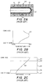
- Fig. 2A is a cross-sectional view of a multilayer preform in a prior art robotic cooling tube
- Fig. 2B is a graph showing the temperature profile across the preform wall
- Fig. 2C is a graph showing the magnitude of shrinkage across the preform wall.
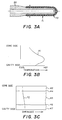
- Fig. 3A is a cross-sectional view of a multilayer preform being cooled on a core in accordance with the present invention
- Fig. 3B is a graph showing the temperature profile across the preform wall
- Fig. 3C is a graph showing the magnitude of shrinkage across the preform wall.
- Fig. 4 is a schematic view of a rotary turret with a plurality of core sets for use in the method of the present invention.
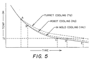
- Fig. 5 is a graph comparing the preform temperature/time profiles for core cooling according to the method of the present invention, in-mold cooling, and the prior art robotic cooling.
- Figs. 6A-6C illustrate the prior art robotic cooling method showing the "mold close” step in Fig. 6A, the "mold open” step in Fig.6B, and the sequence of cooling for three sets of preforms in Fig. 6C.
- Figs. 1-3 illustrate the temperature gradient and shrinkage forces across a multilayer preform wall when it is: within a injection mold (Fig. 1); within a prior art cooling tube (Fig. 2); and on a cooling core in accordance with the present invention (Fig. 3).
- the shrinkage is more uniform through the thickness of the preform sidewall, than in Fig. 2C.
- the shear forces are low, resulting in low delaminating forces.
- Fig. 2C where the nonuniform shrinkage (due to unrestricted core side shrinkage) produces high shear forces between layers, resulting in high delamination forces.
- Figs. 2-3 illustrates how the present invention avoids the high shear force which creates the delamination problem of the prior art.
- Fig. 1A shows a multilayer preform 10 in an injection mold disposed between an elongated mold cavity 20 and cylindrical core 30.
- the preform consists essentially of three portions: an upper neck finish portion 11 (with exterior threads 12 and a neck flange 13), an elongated cylindrical body portion 14, and a closed hemispherical bottom portion 15.
- the mold cavity 20 is similarly composed of an upper neck ring section 21, mid-body-forming section 22, and lower gate pad (base-forming section) 23.
- the mold (and hence the preform) is cooled by flowing chilled water 5 through cooling chapels 6 in the mold.
- the core is similarly cooled by flowing chilled water through the interior 32 of the core.
- the melt streams, for various layers, enter through the gate 24 and flow upwardly between the outer surface 31 of the core and inner surface 25 of the mold cavity, to form the preform.
- Fig. 1B shows a temperature profile 40 across (i.e., from core side to cavity side) a sidewall portion indicated at 41 (see Fig. 1A) of the preform, just prior to removal form the cavity.
- Fig. 1C shows a shrinkage profile 42 across the same sidewall portion 41, due to the temperature gradient.
- a 5-layer preform is provided having inner 43 and outer 47 exterior layers of substantially virgin bottle-grade PET, inner and outer intermediate layers of a high-oxygen barrier material 44 and 46 (e.g., ethylene vinyl alcohol-EVOH), and a central core layer 45 of virgin PET.
- a high-oxygen barrier material 44 and 46 e.g., ethylene vinyl alcohol-EVOH
- PC-PET recycled or post-consumer PET
- PEN polyethylene napthalate
- the intermediate EVOH layers 44, 46 can be very thin (relative to the thickness of the other layers), and provide the desired oxygen barrier property in a cost-effective manner.
- the core layer 45 may be on the order of 50% of the total wall thickness, and the inner and outer layers 43, 47 on the order of 25% each.
- MXD-6 nylon for example, may be used in place of EVOH as a barrier polymer.
- Fig. 2A illustrates a multilayer preform (same as preform 10 of Fig. 1A) being cooled within a prior art robotic cooling tube 50.
- Cooling tube 50 has cooling channels 51, through which chilled water flows, and the preform is cooled primarily from its outer exterior wall, which is (at least initially) in contact with the inner tube wall 52. Some air cooling may occur via the hollow interior of the preform, but primarily the preform cools from the exterior (cavity surface).
- the resulting temperature profile 60 (Fig. 2B) for wall segment 61 shows a hot center, cool outer wall (cavity side) and intermediate inner wall (core side).
- This temperature gradient ad the unconstrained inner layer shrinkage produces higher and nonuniform shrinkage 62 as the warmer core side layers try to shrink away from the cooler cavity side layers (Fig. 2C, compare Fig. 1C), and the result is a weakening of the wall structure and layer separation or delamination below a critical mold cycle time (i.e., approximately 20 seconds for a 4 mm average wall thickness).
- the radial and axial shrinkages are high due to unrestricted internal diameter shrinkage (there is no core). High shrinkage leads to a weakened wall structure, and high shear forces between layers 43-47 (same layers as in Fig. 1). Still further, as the preform shrinks away from the tube wall, the heat transfer becomes less efficient, causing a necessary increase in the cycle time.
- Fig. 3A illustrates a multilayer preform (same preform 10 of Fig. 1A) being cooled on core 30 in accordance with this invention.
- Core 30 is the same core on which the preform is injection molded (in Fig. 1A), but core 30 and preform 10 are removed together from the mold cavity for cooling outside the mold to decrease the cycle time (as explained in detail below).
- Core cooling provides a temperature profile 70 for sidewall segment 71.
- the preform center is hot, the inner (core side) is cool, and the outer (cavity side) is at an intermediate temperature.
- this temperature gradient does not produce delamination because, as the shrinkage profile 72 of Fig. 3C illustrates, the radial and axial shrinkage are low and uniform due to the core restricting the internal diameter shrinkage. The layers are tightly forced together and there are low shear forces between layers.
- Fig. 4 is a schematic illustration of a rotary turret 80, having multiple faces 81-84 (in this example four), each carrying a 2-dimensional array of cores (one core is shown on each face for representative purposes).
- Multiple core sets 90-93 are carried by the rotary turret so that as soon as the injection molded thermoplastic preform material has cooled from a molten fluid to a semi-rigid glassy state sufficient to permit its transfer with its associated core out of the injection mold cavity, the first set of preforms are removed from the mold and the rotating turret immediately presents a new set of free cores to the injection mold cavities.
- the first set of preforms are removed from the mold and the rotating turret immediately presents a new set of free cores to the injection mold cavities.
- there are an array of cores on each face i.e., 16 to 48, or more).
- a injection mold 94 having a array of mold cavities 95 is moved into position over a associated array of cores 90, and multiple thermoplastic melt streams introduced to form a first array of multilayer preforms.
- the first column of Table 1 provides representative times for the various steps, to enable calculation of a complete cycle time, and later comparison with the extended cycle time of the prior art robotic cooling method.
- the mold is open and ready to close at time O, closing the mold and clamp pressure (tonnage) build-up takes 2 seconds, and injection of the various melt streams for the different layers takes 7 seconds.
- the preforms are allowed a minimum cooling time in the mold cavities, here 2 seconds, just enough to enable the preforms (carried by the cores) to be removed from the mold without undergoing any significant distortion.
- the mold is opened by moving the cores away from the cavities, the turret is rotated 90° about a central shaft 96, placing the next set of cores (from station D) into position for molding. It takes about 3 seconds to open the mold and rotate the turret. The total cycle time is thus 14 seconds.
- Turret/Core Cooling (invention) Multiposition Robotic Cooling (prior art) 1. Mold open 0 0 2. Mold close and clamp pressure 2 2 3. Multilayer injection 7 7 4. In-mold cooling 2 6 5. Mold open (rotate turret or prior art robotic removal) 3 5 Total Cycle Time (sec) 14 20
- the first set of preforms are allowed to cool on the cores during one or more mold cycles.
- the preforms cool on the cores for two more cycles (at stations B and C), before being removed from the cores at station D.
- they could be ejected from the cores after only one cycle, depending on the preform thickness and materials.
- the second column of Table I provides representative times for a robotic cooling injection cycle, and illustrates where a time savings results from the present invention.
- the first three steps are the same, but in the fourth step -- cooling in the mold, robotic cooling requires a longer time (here 4 seconds longer). This is because robot cooling requires removal of the preforms off the cores as soon as the mold is open, and thus the preforms must be cooled longer in the mold so they can resist deformation when being stripped from the cores.
- the fifth step takes longer with robot cooling, here 2 seconds longer.
- the robotic cooling method requires mold opening, insertion of the robot arm into position adjacent the cores (between the cores and mold cavities), stripping the preforms from the cores and insertion into the cooling tubes, retraction of the stripper mechanism, and removal of the robot arm (to enable reclosing the same cores in the mold cavities).
- Fig. 5 contains three time/temperature profiles, one for turret cooling (TC) according to this invention, one for robotic cooling (RC) according to the prior art method, and to provide a further basis of comparison, one for continued in-mold cooling (IMC).
- TC mold cooling time according to the present invention
- IMC in-mold cooling
- the mold cooling time according to the present invention (TC) is decreased and thus at time A the mold is opened. This is important for two reasons: 1) decreased cycle time; and 2) the preform will remain at a higher temperature longer.
- the preform Prior to time A, the preform is cooled at a relatively high rate of cooling in the mold; after time A, the rate of cooling is reduced. The rate is higher in the mold because the preform is cooled both by contact with the cold mold cavity and the cold core.
- core cooling the preform's inner surface is in contact with a cold core, but its outer surface is exposed to air which is a less efficient means of heat transfer.
- the mold is opened at a later time B.
- the preform exits the mold at a lower temperature, and is then cooled at a lower rate of cooling (because only one external surface of the preform is in contact with the cold tube cavity, as opposed to both inner and outer surfaces being in contact with cold surfaces in the mold).
- Curve TC (according to the present invention) remains above the critical temperature for the longest time, namely until time E. In contrast, the robotic cooling passes below the critical temperature at an earlier time D, and the in-mold cooling at an even earlier time C.
- 2M3L preforms for 2-liter carbonated soft drink (CSD) containers were prepared.
- the preforms contained 60% (by total preform weight) of virgin PET (nominal 0.80 IV), encapsulating 40% recycled post-consumer PET (nominal IV 0.65).
- These preforms were prepared on a 4-cavity, coinjection system simulating a 14-second cycle as described in column 1 of Table I. The preforms were left on the cores for two cycles (24 seconds) with no external air cooling.
- Control preforms utilizing the same layer structure were produced at a conventional 20-second 3-position robotic cycle.
- Two literTM (i.e., footed) CSD bottles were produced on a conventional 2-stage reheat blow molder.
- core cooling provides improved PET to recycled-PET layer adhesion vs. the conventional robotic cooling approach. It is probable that the early preform removal from the injection cavity results in a higher average preform temperature at the layer boundaries for a longer period of time vs. conventional core and cavity cooling. It is believed that this higher time/temperature condition results in additional molecular ordering and diffusion at the layer boundary, thus yielding improved layer adhesion and delamination resistance. It is believed that any two-polyester material preform having a difference in IV of 0.1 or greater would benefit from the improved delamination resistance according to this invention.
- 2M5L preforms 50 gram, two-material/five-layer (2M5L) preforms were produced in a similar fashion, utilizing virgin PET (nominal IV 0.80) at 98% of the total preform weight, and ethylene vinyl alcohol (EVOH) at 2% of the total preform weight.
- the virgin PET formed inner, core and outer layers, and the EVOH formed inner and outer intermediate layers.
- Conventional and simulated core cooling preforms were produced vs. virgin PET monolayer controls at the same cycle times utilized in the prior example.
- HeinzTM ketchup (28-oz or 0.8 liter) bottles were blown on a 2-stage reheat blow molder, utilizing conventional process conditions. Two hundred bottles from each were filled with water, capped and dropped at room temperature from a height of one meter through a vertical tube onto a steel plate and inspected for layer separation (delamination). The results were as follows: Percent of Bottles With Delamination Virgin PET Monolayer Controls 0% 2M5L Conventional Robotic Cooling 23.5% 2M5L Simulated Core Cooling 8.5%
- the PET/EVOH layers do not utilize the chemical adhesion to effect layer integrity. PET and EVOH are not melt compatible. As such, true molecular adhesion does not occur. Hydrogen bonding, however, provides a sufficient level of layer attraction to prevent layer separation during normal use conditions. (Upon severe abuse, i.e., mechanical grinding, the layers separate, permitting the materials to be sorted for recycling, etc.) It is believed that the higher time/temperature conditions experienced by the layer boundaries of the simulated core cooling samples results in increased polymer mobility/ordering and higher levels of hydrogen bonding, yielding an increase in resistance to drop impact delamination.
- Thermoplastic polymer materials which may be used in this invention are preferably polyesters based on polyalkylene, and in particular, polyethylene terephthalate (PET).
- PET polymers are prepared by polymerizing terephthalic acid or its ester-forming derivative with ethylene.
- the polymer comprises repeating units of ethylene terephthalate of the formula:
- PET means PET homopolymer and PET copolymers of the grades suitable for making containers, which are well known in the art.
- the glycol moiety of the monomer may be replaced by aliphatic or alicyclic glycols such as cyclohexanedimethanol (CHDM), trimethylene glycol, polytetramethylene glycol, hexamethylene glycol, dodecamethylene glycol, diethylene glycol, polyethylene glycol, polypropylene glycol, propane-1,3-diol, butane-1,4-diol, and neopentyl glycol, bisphenols, and other aromatic diols such as hydroquinone and 2,2-bis(4'-B-hydroxy-ethoxyphenyl) propane.
- CHDM cyclohexanedimethanol
- trimethylene glycol polytetramethylene glycol
- hexamethylene glycol hexamethylene glycol
- dodecamethylene glycol diethylene glycol
- polyethylene glycol polypropylene glycol
- propane-1,3-diol propane-1,3-diol
- dicarboxylic acid moieties which may be substituted into the monomer unit include aromatic dicarboxylic acids such as isophthalic acid (IPA), phthalic acid, naphthalenedicarboxylic acid, diphenyldicarboxylic acid, diphenoxyethanedicarboxylic acids, bibenzoic acid, and aliphataic or alicyclic dicarboxylic acids such as adipic acid, sebacic acid, azelaic acid, decanedicarboxylic acid and cyclohexanedicarboxylic acid.
- aromatic dicarboxylic acids such as isophthalic acid (IPA), phthalic acid, naphthalenedicarboxylic acid, diphenyldicarboxylic acid, diphenoxyethanedicarboxylic acids, bibenzoic acid, and aliphataic or alicyclic dicarboxylic acids such as adipic acid, sebacic acid, azelaic acid, decanedica
- the polyethylene terephthalate polymers may contain other compatible additives and ingredients which do not adversely affect the performance characteristics of the container, such as adversely affecting the taste or other properties of products packaged therein.
- ingredients include thermal stabilizers, light stabilizers, dyes, pigments, plasticizers, fillers, antitoxidants, lubricants, extrusion aids, residual monomer scavengers and the like.
- the intrinsic viscosity effects the processability of the polyester resins.
- Polyethylene terephthalate having an intrinsic viscosity of about 0.8 is widely used in the CSD industry. Resins for various applications may range from about 0.55 to about 1.04, and more particularly from about 0.65 to 0.85.
- Intrinsic viscosity measurements are made according to the procedure of ASTM D-2857, by employing 0.0050 ⁇ 0.0002 g/ml of the polymer in a solvent comprising o-chlorophenol (melting point 0°C), respectively, at 30°C.
- PETG a commercially-available, relatively high copolymer content
- PETG a commercially-available, relatively high copolymer content
- PEN polyethylene naphthalate
- Polyolefins may also be used as the base polymer.
- Other options include acrylic/imide, polyamides (both aromatic and aliphatic), amorphous nylon, and acrylonitrile styrene.
- a preferred aromatic polyamide is a polymer formed by polymerizing metaxylylenediamine (H 2 NCH 2 -m-C 6 H 4 -CH 2 NH 2 ) with adipic acid (HO 2 C(CH 2 ) 4 CO 2 H), for example a product manufactured and sold by MitsubishiChemicals, Japan, under the designation MXD-6.
- a preferred polyamide of non-aromatic nature is nylon-6,6. Copolymers of polyamides and other polymers may be used.
- Oxygen barrier layers other than EVOH and PEN may include polyvinyl alcohol (PVOH), polyvinyldene chloride (PVDC), nylon 6, MXD-6, LCP (liquid crystal polymer), amorphous nylon, polyacrylonitrile (PAN) and styrene acrylonitrile (SAN).
- PVH polyvinyl alcohol
- PVDC polyvinyldene chloride
- nylon 6 MXD-6
- LCP liquid crystal polymer
- amorphous nylon polyacrylonitrile
- PAN polyacrylonitrile
- SAN styrene acrylonitrile
- the molding equipment e.g., vertical injection molding, horizontal injection molding, extrusion molding, size of mold cavity and core arrays, etc.
- the preform structure e.g., number of layers, shape, dimensions, thickness of layers, etc.
- thermoplastic polymers e.g., polyester, polypropylene, polyvinyl chloride, etc.
- other layer materials e.g., oxygen barrier, moisture barrier, carbon dioxide barrier, thermal resistant, recycled polymers, colored, etc.
Landscapes
- Engineering & Computer Science (AREA)
- Manufacturing & Machinery (AREA)
- Mechanical Engineering (AREA)
- Processing And Handling Of Plastics And Other Materials For Molding In General (AREA)
- Blow-Moulding Or Thermoforming Of Plastics Or The Like (AREA)
- Laminated Bodies (AREA)
- Moulds For Moulding Plastics Or The Like (AREA)
Claims (30)
- Verfahren zum Herstellen mehrschichtiger Kunststoff-Vorformlinge (10), bei dem man eine erste Gruppe von Kernen (90) in eine zugehörige Gruppe von Formhohlräumen (95) einsetzt, die Formhohlräume füllt, um auf der ersten Gruppe von Kernen eine erste Vielzahl mehrschichtiger Vorformlinge auszubilden, die erste Gruppe von Vorformlingen in der Form durch den Kontakt mit den Formhohlräumen und den Kernen mit einer verhältnismäßig hohen ersten Kühlgeschwindigkeit abkühlt und dann die erste Gruppe von Vorformlingen aus den Formhohlräumen zwecks weiterer Kühlung entfernt, wobei man nach diesem Verfahrendie Kühlzeit in der Form verkürzt, indem man die erste Gruppe von Kernen und von Vorformlingen aus den Formhohlräumen entfernt, sobald die Vorformlinge in der Lage sind, ohne wesentliche körperliche Verformung auf den Kernen abzukühlen, unddie mehrschichtigen Vorformlinge auf den Kernen mit einer zweiten Kühlgeschwindigkeit kühlt, die verhältnismäßig niedriger als die erste Kühlgeschwindigkeit ist, um die Vorformlinge länger auf einer höheren Temperatur zu halten und eine Zunahme der Molekülordnung, -diffusion und/oder -bindung an den Grenzflächen zwischen den Schichten zu ermöglichen, so daß man einen verbesserten Widerstand gegen Delamination erhält.
- Verfahren nach Anspruch 1, bei dem man weiterhinin den Formhohlräumen eine zweite Gruppe von Kernen (93) vorsieht, um eine zweite Vielzahl mehrschichtiger Vorformlinge auszubilden, während die erste Vielzahl von Vorformlingen auf der ersten Kerngruppe außerhalb der Formhohlräume abkühlt.
- Verfahren nach Anspruch 2, bei dem die erste und die zweite Gruppe von Kernen auf einem Revolver (80) vorgesehen sind, der gedreht wird, um die erste und die zweite Kerngruppe nacheinander in die Formhohlräume einzubringen.
- Verfahren nach Anspruch 3, bei dem man weiterhin auf dem Revolver zusätzliche Gruppen von Kernen (91, 92) vorsieht und die Vorformlinge auf den Kernen länger als einen Formzyklus kühlen läßt.
- Verfahren nach Anspruch 1, bei dem zwischen den Schichten der Vorformlinge eine Molekülbindung erfolgt.
- Verfahren nach Anspruch 1, bei dem die mehreren Schichten nebeneinanderliegende Schichten aus Polyester-Polymerisaten mit einer Differenz der Eigenviskosität von mehr als größenordnungmäßig 0,1 aufweisen.
- Verfahren nach Anspruch 6, bei der eine Polyesterschicht frisches Polyethylenterephthalat (PET) und eine angrenzende Schicht rezykliertes Polyethylenterephthalat ist.
- Verfahren nach Anspruch 1, bei dem die mehreren Schichten aneinandergrenzende Schichten aus Polymerisatharzen aufweisen, die nicht schmelzkompatibel sind.
- Verfahren nach Anspruch 1, bei dem zwischen den Schichten der Vorformlinge eine Wasserstoffbindung vorliegt.
- Verfahren nach Anspruch 9, bei dem eine Schicht Polyethylenterephthalat (PET) und eine angrenzende Schicht Ethylenvinylalkohol (EVOH) ist.
- Verfahren nach Anspruch 8, bei dem eine Schicht Polyethylenterephthalat (PET) und eine angrenzende Schicht MXD-6-Nylon ist.
- Verfahren nach Anspruch 3, bei dem die Zykluszeit in der Größenordnung von zwei Sekunden liegt.
- Verfahren nach Anspruch 1, bei dem die Abkühlzeit in der Form auf nicht mehr als etwa zwei Sekunden verkürzt wird.
- Verfahren nach Anspruch 1, bei dem die mehreren Schichten aneinandergrenzende Schichten aus unterschiedlichen Polymerisaten ohne Klebstoffe sind.
- Verfahren nach Anspruch 1, bei dem der Vorformling eine Seitenwand mit einer dem Kern zugewandten Kernseite, eine dem Formhohlraum zugewandten Hohlraumseite sowie eine Mitte zwischen der Kern- und der Hohlraumseite aufweist und bei dem beim Abkühlen auf den Kernen außerhalb der Form ein Temperaturgefälle über die Seitenwand des Vorformlings auftritt, bei dem die Kernseite verhältnismäßig kühler und die Mitte im Vergleich zur Kernseite verhältnismäßig wärmer sind und die Hohlraumseite temperaturmäßig zwischen der Kern- und der Hohlraumseite liegt, wobei infolge der Begrenzung der kernseitigen Schrumpfung durch den Kern die radialen und axialen Schrumpfungskräfte über die Seitenwand niedrig und gleichmäßig sind.
- Verfahren nach Anspruch 1, bei dem der Vorformling eine Seitenwand aufweist und beim Abkühlen auf den Kernen außerhalb der Form das Ausmaß der Schrumpfung über die Seitenwand des Vorformlings im wesentlichen konstant ist.
- Verfahren nach Anspruch 1, bei dem der Vorformling eine Seitenwand aufweist und beim Abkühlen auf den Kernen außerhalb der Form niedrige radiale und axiale Schrumpfungskräfte über die Seitenwand des Vorformlings auftreten.
- Verfahren nach Anspruch 1, bei dem der Vorformling eine Seitenwand mit einer an den Formhohlraum angrenzenden äußeren Hohlraumseite aufweist und die Vorformlinge aus den Formhohlräumen herausgenommen werden, sobald die äußere Hohlraumseite des Vorformlings von einem Schmelzzustand zu einem halbstarren glasigen Zustand abgekühlt ist.
- Verfahren nach Anspruch 1, bei dem die Formhohlräume und die Kerne Kühlkanäle (51) aufweisen, durch die ein Kühlfluid geführt wird.
- Verfahren nach Anspruch 1, bei dem dieses für die großmaßstäbliche gewerbliche Produktion von Vorformlingen für blasgeformte Behälter eingesetzt wird.
- Verfahren nach Anspruch 20, bei dem die Behälter Getränkebehälter für die einmalige Verwendung sind.
- Verfahren nach Anspruch 1, bei dem die Dauer verlängert wird, während der die Schichten des Vorformlings über einer kritischen Temperatur bleiben, die eine Verstärkung der Molekülordnung, -diffusion und/oder -bindung an den Grenzflächen zwischen den Schichten erlaubt.
- Verfahren nach Anspruch 1, bei dem die aus den Vorformlingen blasgeformten Behälter eine reduzierte Häufigkeit des Versagens durch Delamination aufweisen.
- Verfahren nach Anspruch 1, bei dem weiterhin der abgekühlte Vorformling an einen Förderer oder Lagerbehälter übergeben wird und bei dem die zusammengenommene Abkühlzeit in der Form und auf dem Kern verkürzt wird.
- Verfahren nach Anspruch 1, bei dem die Formgebung durch Spritzformen erfolgt.
- Verfahren nach Anspruch 1, bei dem die mehreren Schichten Schichten aus thermoplastischen Polymerisaten aufweisen.
- Verfahren nach Anspruch 26, bei dem die thermoplastischen Polymerisate aus der aus Polyestern, Polyolefinen, Acrylimiden, Polyamiden, amorphem Nylon und Acrylnitrilstyrol bestehenden Gruppe gewählt sind.
- Verfahren nach Anspruch 27, bei dem die Polyester aus der aus frischem und rezykliertem Polyethylenterephthalat (PET), Polyethylennaphthalat (PEN), Cyclohexandimethanol/PET (PETG) und deren Copolymerisaten bestehenden Gruppe gewählt sind.
- Verfahren nach Anspruch 26, bei dem die mehreren Schichten Schichten aus Sperrschichtmaterialien aufweisen, die aus der aus Sauerstoff-, Feuchte- und Kohlendioxidsperrstoffen bestehenden Gruppe gewählt sind.
- Verfahren nach Anspruch 29, bei dem die Sperrstoffe Sauerstoffsperrstoffe sind, die aus der aus Ethylenvinylalkohol (EVOH), Polyethylennaphthalat (PEN), Polyvinylalkohol (PVOH), Polyvinylidenchlorid (PVDC), Nylon 6, MXD-6, Flüssigkristallpolymerisat (LCP), amorphem Nylon, Polyacrylnitril (PAN) und Styrolacrylnitril (SAH) bestehenden Gruppe gewählt sind.
Applications Claiming Priority (3)
| Application Number | Priority Date | Filing Date | Title |
|---|---|---|---|
| US365205 | 1994-12-28 | ||
| US08/365,205 US5582788A (en) | 1994-12-28 | 1994-12-28 | Method of cooling multilayer preforms |
| PCT/US1995/017011 WO1996020074A1 (en) | 1994-12-28 | 1995-12-27 | Method of cooling multilayer preforms |
Publications (2)
| Publication Number | Publication Date |
|---|---|
| EP0800446A1 EP0800446A1 (de) | 1997-10-15 |
| EP0800446B1 true EP0800446B1 (de) | 1998-11-25 |
Family
ID=23437904
Family Applications (1)
| Application Number | Title | Priority Date | Filing Date |
|---|---|---|---|
| EP95944427A Expired - Lifetime EP0800446B1 (de) | 1994-12-28 | 1995-12-27 | Verfahren zum kühlen von mehrschichtigen vorformlingen |
Country Status (13)
| Country | Link |
|---|---|
| US (1) | US5582788A (de) |
| EP (1) | EP0800446B1 (de) |
| JP (1) | JP4135163B2 (de) |
| CN (1) | CN1067936C (de) |
| AT (1) | ATE173668T1 (de) |
| AU (1) | AU690419B2 (de) |
| BR (1) | BR9510225A (de) |
| CA (1) | CA2208867C (de) |
| DE (1) | DE69506283T2 (de) |
| ES (1) | ES2126338T3 (de) |
| HU (1) | HU217190B (de) |
| NZ (1) | NZ301131A (de) |
| WO (1) | WO1996020074A1 (de) |
Families Citing this family (59)
| Publication number | Priority date | Publication date | Assignee | Title |
|---|---|---|---|---|
| US5804016A (en) * | 1996-03-07 | 1998-09-08 | Continental Pet Technologies, Inc. | Multilayer container resistant to elevated temperatures and pressures, and method of making the same |
| JP3808173B2 (ja) * | 1997-05-20 | 2006-08-09 | 日精エー・エス・ビー機械株式会社 | プリフォーム成形機及びプリフォーム成形方法 |
| US6322738B1 (en) | 1997-07-24 | 2001-11-27 | Husky Injection Molding Systems Ltd. | Method of injection over-molding articles |
| US6090337A (en) | 1997-07-30 | 2000-07-18 | Plastipak Packaging, Inc. | Method for making multi-layer plastic preform for blow molding |
| TWI250934B (en) * | 1997-10-17 | 2006-03-11 | Advancsd Plastics Technologies | Barrier-coated polyester articles and the fabrication method thereof |
| US6312641B1 (en) | 1997-10-17 | 2001-11-06 | Plastic Fabrication Technologies Llc | Method of making containers and preforms incorporating barrier materials |
| US6352426B1 (en) | 1998-03-19 | 2002-03-05 | Advanced Plastics Technologies, Ltd. | Mold for injection molding multilayer preforms |
| JPH11192656A (ja) * | 1997-12-29 | 1999-07-21 | Nihon Yamamura Glass Co Ltd | 多層プリフォーム、その成形方法及び多層ボトル |
| CA2326449C (en) * | 1998-03-31 | 2007-10-02 | Husky Injection Molding Systems, Inc. | Preform post-mold cooling method and apparatus |
| US6171541B1 (en) | 1998-03-31 | 2001-01-09 | Husky Injection Molding Systems Ltd. | Preform post-mold cooling method and apparatus |
| US6522930B1 (en) * | 1998-05-06 | 2003-02-18 | Atrionix, Inc. | Irrigated ablation device assembly |
| US6147128A (en) * | 1998-05-14 | 2000-11-14 | Astenjohnson, Inc. | Industrial fabric and yarn made from recycled polyester |
| DE19848334C2 (de) * | 1998-10-20 | 2001-08-16 | Karl Hehl | Spritzgießmaschine mit einem Handhabungsgerät |
| CA2255800C (en) * | 1998-12-07 | 2008-06-10 | Jobst Ulrich Gellert | Injection molding cooling core having a ribbed cap |
| US6244073B1 (en) * | 1999-02-05 | 2001-06-12 | Dennis John Kaping, Jr. | Body jewelry cap |
| US6655945B1 (en) | 1999-03-18 | 2003-12-02 | Mold Masters Limited | Apparatus and method for multi-layer injection molding |
| US6440350B1 (en) | 1999-03-18 | 2002-08-27 | Mold-Masters Limited | Apparatus and method for multi-layer injection molding |
| US6398537B2 (en) | 1999-04-02 | 2002-06-04 | Mold-Masters Limited | Shuttle system for an apparatus for injection molding |
| WO2000073040A1 (en) * | 1999-05-17 | 2000-12-07 | Jes Tougaard Gram | Mould with turnable middle section |
| US6196826B1 (en) | 1999-05-28 | 2001-03-06 | Mold-Masters Limited | Seepage system for an injection molding apparatus |
| US6276922B1 (en) | 1999-08-24 | 2001-08-21 | Husky Injection Molding Systems Ltd. | Core fluid velocity inducer |
| ITPN20000006A1 (it) * | 2000-01-26 | 2001-07-26 | Sipa Spa | Impianto a torre rotante su asse orizzontale per la movimentazione dipreforme |
| AU2001288916B2 (en) | 2000-09-05 | 2007-05-10 | Advanced Plastics Technologies Luxembourg S.A. | Multilayer containers and preforms having barrier properties utilizing recycled material |
| KR20040050926A (ko) | 2001-10-24 | 2004-06-17 | 페쉬니 앙발라쥬 플렉서블 유럽 | 폴리프로필렌 용기 및 그 제조 방법 |
| DE10215722B4 (de) * | 2002-04-10 | 2009-11-26 | Husky Injection Molding Systems Ltd., Bolton | Verfahren und Vorrichtung zur Bearbeitung von Vorformlingen |
| AU2003267163A1 (en) * | 2002-09-13 | 2004-04-30 | Ultra Tool Group, Lp | Injection molding equipment having molded article ejector, and method |
| US20050260371A1 (en) * | 2002-11-01 | 2005-11-24 | Yu Shi | Preform for low natural stretch ratio polymer, container made therewith and methods |
| US20040091651A1 (en) * | 2002-11-01 | 2004-05-13 | Mark Rule | Pet copolymer composition with enhanced mechanical properties and stretch ratio, articles made therewith, and methods |
| AU2003285192A1 (en) | 2002-11-08 | 2004-06-03 | Advanced Plastics Technologies Ltd | Injection mold having a wear resistant portion and a high heat transfer portion and a method for forming a preform |
| US20060237882A1 (en) * | 2002-12-26 | 2006-10-26 | Graham Packaging Company L.P. | Amorphous nylon container and method of manufacture |
| US7264464B2 (en) * | 2003-06-09 | 2007-09-04 | Husky Injection Molding Systems Ltd. | Cooling tube with a low friction coating |
| EP1636289B1 (de) * | 2003-06-18 | 2009-09-16 | The Coca-Cola Company | Verfharen zur heissbefüllung von behältern, die aus polyesterzusammensetzungen hergestellt sind |
| US7128553B2 (en) | 2003-09-26 | 2006-10-31 | Advance Tool, Inc. | Injection molding apparatus and method |
| US20050221036A1 (en) * | 2004-04-01 | 2005-10-06 | The Coca-Cola Company | Polyester composition with enhanced gas barrier, articles made therewith, and methods |
| ES2321421T3 (es) | 2004-04-16 | 2009-06-05 | Advanced Plastics Technologies Luxembourg S.A. | Reforma y procedimientos de fabricacion de la preforma y una botella. |
| US7632089B2 (en) * | 2004-05-07 | 2009-12-15 | Graham Packaging Pet Technologies, Inc. | Take out and cooling system and method |
| BRPI0511664A (pt) | 2004-06-10 | 2008-01-02 | Advanced Plastics Technologies | métodos e sistemas para o controle de temperaturas de moldes |
| JP2006150638A (ja) * | 2004-11-26 | 2006-06-15 | Hitachi Industrial Equipment Systems Co Ltd | ディスク成形方法及びその金型 |
| NZ561814A (en) * | 2005-03-15 | 2010-12-24 | Coca Cola Co | Overmolded containers and methods of manufacture and use thereof |
| US7572493B2 (en) * | 2005-05-11 | 2009-08-11 | The Coca-Cola Company | Low IV pet based copolymer preform with enhanced mechanical properties and cycle time, container made therewith and methods |
| US7820257B2 (en) * | 2005-05-11 | 2010-10-26 | The Coca-Cola Company | Preforms for preparing lightweight stretch blow molded PET copolymer containers and methods for making and using same |
| US7717697B2 (en) | 2005-08-30 | 2010-05-18 | Sharon Hutchinson | Methods and systems for controlling mold temperatures |
| US20150266231A1 (en) | 2007-04-19 | 2015-09-24 | Anheuser-Busch Inbev S.A. | Integrally blow-moulded bag-in-container having a bag anchoring point; process for the production thereof; and tool thereof |
| US9919841B2 (en) | 2007-04-19 | 2018-03-20 | Anheuser-Busch Inbev S.A. | Integrally blow-moulded bag-in-container having interface vents opening to the atmosphere at location adjacent to bag's mouth, preform for making it; and processes for producing the preform and bag-in-container |
| US20080258356A1 (en) | 2007-04-19 | 2008-10-23 | Inbev S.A. | Integrally blow-moulded bag-in-container comprising an inner layer and an outer layer comprising energy absorbing additives, and preform for making it |
| US20080257883A1 (en) | 2007-04-19 | 2008-10-23 | Inbev S.A. | Integrally blow-moulded bag-in-container having an inner layer and the outer layer made of the same material and preform for making it |
| US20080257846A1 (en) * | 2007-04-19 | 2008-10-23 | Inbev S.A. | Integrally blow-moulded bag-in-container having interface vents opening to the atmosphere at location adjacent to bag's mouth; preform for making it; and processes for producing the preform and bag-in-container |
| US7946836B2 (en) | 2008-05-23 | 2011-05-24 | Roberto Sicilia | Injection molding and temperature conditioning apparatus |
| GB2474026B (en) * | 2009-09-30 | 2012-12-26 | Peter Reginald Clarke | Injection molding material |
| US8822001B2 (en) | 2010-04-27 | 2014-09-02 | Graham Packaging Company, L.P. | Delamination resistant multilayer containers |
| US9074092B2 (en) | 2010-12-20 | 2015-07-07 | Eastman Chemical Company | Miscible polyester blends utilizing recycled polyesters |
| US10583602B2 (en) * | 2016-03-11 | 2020-03-10 | Ring Container Technologies, Llc | Container and method of manufacture |
| US20180001529A1 (en) * | 2016-06-30 | 2018-01-04 | iMFLUX Inc. | Injection molding with targeted heating of mold cavities in a non-molding position |
| AU2017367908B2 (en) | 2016-11-30 | 2022-02-17 | Kimberly-Clark Worldwide, Inc. | Thermoplastic injection molded and flushable material |
| AU2017366807B2 (en) | 2016-11-30 | 2022-02-17 | Kimberly-Clark Worldwide, Inc. | Thermoplastic injection molded and flushable tampon applicator |
| CH715582A1 (de) * | 2018-11-22 | 2020-05-29 | Alpla Werke Alwin Lehner Gmbh & Co Kg | Kunststoffbehälter mit wenigstens bereichsweise scharfkantig ausgebildeter Behältergeometrie und Verfahren zur Herstellung des Kunststoffbehälters. |
| CN109760268B (zh) * | 2019-02-20 | 2021-02-26 | 昆山联滔电子有限公司 | 一种塑胶件的成型方法及塑胶件 |
| WO2021060196A1 (ja) * | 2019-09-25 | 2021-04-01 | 日精エー・エス・ビー機械株式会社 | ブロー成形装置およびブロー成形方法 |
| SE544880C2 (en) * | 2020-05-11 | 2022-12-20 | Stora Enso Oyj | Multilayer preform and container |
Family Cites Families (16)
| Publication number | Priority date | Publication date | Assignee | Title |
|---|---|---|---|---|
| CH477274A (de) * | 1968-08-08 | 1969-08-31 | Barmag Barmer Maschf | Vorrichtung zum Herstellen mehrschichtiger Blasfolien oder -schläuche |
| US4201535A (en) * | 1976-11-03 | 1980-05-06 | Owens-Illinois, Inc. | Apparatus for forming tubular plastic articles |
| US4246225A (en) * | 1978-05-25 | 1981-01-20 | Owens-Illinois, Inc. | Method for forming tubular plastic articles |
| US4568261A (en) * | 1979-07-20 | 1986-02-04 | American Can Company | Apparatus for making a multi-layer injection blow molded container |
| US4330257A (en) * | 1979-11-15 | 1982-05-18 | Husky Injection Molding Systems, Inc. | Turret-type injection-molding machine |
| US4313905A (en) * | 1979-11-26 | 1982-02-02 | Hafele Robert X | Blow molding method |
| AU549286B2 (en) * | 1981-01-22 | 1986-01-23 | Toyo Boseki K.K. | Blow moulded multiply vessel |
| US4786455A (en) * | 1981-02-23 | 1988-11-22 | The Continental Group, Inc. | Rotary injection turret and method of utilizing the same in the making of preforms |
| JPS6189014A (ja) * | 1984-10-06 | 1986-05-07 | Nissei Ee S B Kikai Kk | パリソン射出成形方法 |
| JPS61152411A (ja) * | 1984-12-26 | 1986-07-11 | Mitsubishi Gas Chem Co Inc | 多層パリソン及びその製造方法 |
| JPS61230911A (ja) * | 1985-04-08 | 1986-10-15 | Toyo Seikan Kaisha Ltd | 延伸ブロ−成形用多層プリフオ−ムの共射出成形装置 |
| GB8616460D0 (en) * | 1986-07-05 | 1986-08-13 | Metal Box Plc | Manufacture of articles |
| US4836767A (en) * | 1987-11-25 | 1989-06-06 | Husky Injection Molding System, Ltd. | Swing plate molding machine |
| US4990301A (en) * | 1989-01-25 | 1991-02-05 | Continental Pet Technologies, Inc. | Method and apparatus for injection molding of multilayer preforms |
| NL9000414A (nl) * | 1990-02-21 | 1991-09-16 | Tooling Preform Systems B V | Werkwijze en inrichting voor het vervaardigen van voorvormen voor kunststofflessen. |
| JPH0790595B2 (ja) * | 1990-10-15 | 1995-10-04 | 日精エー・エス・ビー機械株式会社 | プリフォームの冷却装置 |
-
1994
- 1994-12-28 US US08/365,205 patent/US5582788A/en not_active Expired - Fee Related
-
1995
- 1995-12-27 AU AU46478/96A patent/AU690419B2/en not_active Ceased
- 1995-12-27 CN CN95197165A patent/CN1067936C/zh not_active Expired - Fee Related
- 1995-12-27 AT AT95944427T patent/ATE173668T1/de not_active IP Right Cessation
- 1995-12-27 WO PCT/US1995/017011 patent/WO1996020074A1/en not_active Ceased
- 1995-12-27 DE DE69506283T patent/DE69506283T2/de not_active Expired - Fee Related
- 1995-12-27 JP JP52060196A patent/JP4135163B2/ja not_active Expired - Fee Related
- 1995-12-27 ES ES95944427T patent/ES2126338T3/es not_active Expired - Lifetime
- 1995-12-27 HU HU9701816A patent/HU217190B/hu not_active IP Right Cessation
- 1995-12-27 NZ NZ301131A patent/NZ301131A/en unknown
- 1995-12-27 CA CA002208867A patent/CA2208867C/en not_active Expired - Fee Related
- 1995-12-27 EP EP95944427A patent/EP0800446B1/de not_active Expired - Lifetime
- 1995-12-27 BR BR9510225A patent/BR9510225A/pt not_active IP Right Cessation
Also Published As
| Publication number | Publication date |
|---|---|
| NZ301131A (en) | 1999-10-28 |
| HUT76986A (hu) | 1998-01-28 |
| CA2208867A1 (en) | 1996-07-04 |
| EP0800446A1 (de) | 1997-10-15 |
| WO1996020074A1 (en) | 1996-07-04 |
| BR9510225A (pt) | 1997-11-04 |
| JP4135163B2 (ja) | 2008-08-20 |
| CN1067936C (zh) | 2001-07-04 |
| CN1171755A (zh) | 1998-01-28 |
| ATE173668T1 (de) | 1998-12-15 |
| AU4647896A (en) | 1996-07-19 |
| DE69506283D1 (de) | 1999-01-07 |
| MX9704821A (es) | 1997-10-31 |
| DE69506283T2 (de) | 1999-05-06 |
| US5582788A (en) | 1996-12-10 |
| CA2208867C (en) | 2007-05-08 |
| JPH10511617A (ja) | 1998-11-10 |
| HU217190B (hu) | 1999-12-28 |
| ES2126338T3 (es) | 1999-03-16 |
| AU690419B2 (en) | 1998-04-23 |
Similar Documents
| Publication | Publication Date | Title |
|---|---|---|
| EP0800446B1 (de) | Verfahren zum kühlen von mehrschichtigen vorformlingen | |
| US6787094B2 (en) | Sleeve molding | |
| EP1147872B1 (de) | Verfahren zum Formen von mehrschichtigen Kunststoffgegenständen | |
| EP0653981B1 (de) | Verfahren zum formen eines mehrlagigen vorformlings und behälter mit niedrig kristalliner innenschicht | |
| AU2001288916B2 (en) | Multilayer containers and preforms having barrier properties utilizing recycled material | |
| AU2001288916A1 (en) | Multilayer containers and preforms having barrier properties utilizing recycled material | |
| KR20000048355A (ko) | 플라스틱 병 및 그 제조 방법 | |
| MXPA97004821A (en) | Method for cooling multip layer preforms | |
| CA2436981A1 (en) | Sleeve molding |
Legal Events
| Date | Code | Title | Description |
|---|---|---|---|
| PUAI | Public reference made under article 153(3) epc to a published international application that has entered the european phase |
Free format text: ORIGINAL CODE: 0009012 |
|
| 17P | Request for examination filed |
Effective date: 19970704 |
|
| AK | Designated contracting states |
Kind code of ref document: A1 Designated state(s): AT BE CH DE DK ES FR GB GR IE IT LI LU MC NL PT SE |
|
| GRAG | Despatch of communication of intention to grant |
Free format text: ORIGINAL CODE: EPIDOS AGRA |
|
| 17Q | First examination report despatched |
Effective date: 19980122 |
|
| GRAG | Despatch of communication of intention to grant |
Free format text: ORIGINAL CODE: EPIDOS AGRA |
|
| GRAH | Despatch of communication of intention to grant a patent |
Free format text: ORIGINAL CODE: EPIDOS IGRA |
|
| GRAH | Despatch of communication of intention to grant a patent |
Free format text: ORIGINAL CODE: EPIDOS IGRA |
|
| GRAA | (expected) grant |
Free format text: ORIGINAL CODE: 0009210 |
|
| AK | Designated contracting states |
Kind code of ref document: B1 Designated state(s): AT BE CH DE DK ES FR GB GR IE IT LI LU MC NL PT SE |
|
| PG25 | Lapsed in a contracting state [announced via postgrant information from national office to epo] |
Ref country code: SE Free format text: LAPSE BECAUSE OF FAILURE TO SUBMIT A TRANSLATION OF THE DESCRIPTION OR TO PAY THE FEE WITHIN THE PRESCRIBED TIME-LIMIT Effective date: 19981125 Ref country code: NL Free format text: LAPSE BECAUSE OF FAILURE TO SUBMIT A TRANSLATION OF THE DESCRIPTION OR TO PAY THE FEE WITHIN THE PRESCRIBED TIME-LIMIT Effective date: 19981125 Ref country code: LI Free format text: LAPSE BECAUSE OF FAILURE TO SUBMIT A TRANSLATION OF THE DESCRIPTION OR TO PAY THE FEE WITHIN THE PRESCRIBED TIME-LIMIT Effective date: 19981125 Ref country code: GR Free format text: LAPSE BECAUSE OF NON-PAYMENT OF DUE FEES Effective date: 19981125 Ref country code: CH Free format text: LAPSE BECAUSE OF FAILURE TO SUBMIT A TRANSLATION OF THE DESCRIPTION OR TO PAY THE FEE WITHIN THE PRESCRIBED TIME-LIMIT Effective date: 19981125 Ref country code: BE Free format text: LAPSE BECAUSE OF FAILURE TO SUBMIT A TRANSLATION OF THE DESCRIPTION OR TO PAY THE FEE WITHIN THE PRESCRIBED TIME-LIMIT Effective date: 19981125 Ref country code: AT Free format text: LAPSE BECAUSE OF FAILURE TO SUBMIT A TRANSLATION OF THE DESCRIPTION OR TO PAY THE FEE WITHIN THE PRESCRIBED TIME-LIMIT Effective date: 19981125 |
|
| REF | Corresponds to: |
Ref document number: 173668 Country of ref document: AT Date of ref document: 19981215 Kind code of ref document: T |
|
| REG | Reference to a national code |
Ref country code: CH Ref legal event code: EP |
|
| PGFP | Annual fee paid to national office [announced via postgrant information from national office to epo] |
Ref country code: DK Payment date: 19981214 Year of fee payment: 4 |
|
| PGFP | Annual fee paid to national office [announced via postgrant information from national office to epo] |
Ref country code: AT Payment date: 19981215 Year of fee payment: 4 |
|
| PGFP | Annual fee paid to national office [announced via postgrant information from national office to epo] |
Ref country code: SE Payment date: 19981218 Year of fee payment: 4 |
|
| PGFP | Annual fee paid to national office [announced via postgrant information from national office to epo] |
Ref country code: IE Payment date: 19981221 Year of fee payment: 4 |
|
| PGFP | Annual fee paid to national office [announced via postgrant information from national office to epo] |
Ref country code: MC Payment date: 19981223 Year of fee payment: 4 |
|
| PGFP | Annual fee paid to national office [announced via postgrant information from national office to epo] |
Ref country code: LU Payment date: 19990104 Year of fee payment: 4 |
|
| PGFP | Annual fee paid to national office [announced via postgrant information from national office to epo] |
Ref country code: BE Payment date: 19990106 Year of fee payment: 4 |
|
| REF | Corresponds to: |
Ref document number: 69506283 Country of ref document: DE Date of ref document: 19990107 |
|
| REG | Reference to a national code |
Ref country code: IE Ref legal event code: FG4D |
|
| ET | Fr: translation filed | ||
| ITF | It: translation for a ep patent filed | ||
| PG25 | Lapsed in a contracting state [announced via postgrant information from national office to epo] |
Ref country code: PT Free format text: LAPSE BECAUSE OF FAILURE TO SUBMIT A TRANSLATION OF THE DESCRIPTION OR TO PAY THE FEE WITHIN THE PRESCRIBED TIME-LIMIT Effective date: 19990225 Ref country code: DK Free format text: LAPSE BECAUSE OF FAILURE TO SUBMIT A TRANSLATION OF THE DESCRIPTION OR TO PAY THE FEE WITHIN THE PRESCRIBED TIME-LIMIT Effective date: 19990225 |
|
| REG | Reference to a national code |
Ref country code: ES Ref legal event code: FG2A Ref document number: 2126338 Country of ref document: ES Kind code of ref document: T3 |
|
| NLV1 | Nl: lapsed or annulled due to failure to fulfill the requirements of art. 29p and 29m of the patents act | ||
| REG | Reference to a national code |
Ref country code: CH Ref legal event code: PL |
|
| PLBE | No opposition filed within time limit |
Free format text: ORIGINAL CODE: 0009261 |
|
| STAA | Information on the status of an ep patent application or granted ep patent |
Free format text: STATUS: NO OPPOSITION FILED WITHIN TIME LIMIT |
|
| 26N | No opposition filed | ||
| PG25 | Lapsed in a contracting state [announced via postgrant information from national office to epo] |
Ref country code: LU Free format text: LAPSE BECAUSE OF NON-PAYMENT OF DUE FEES Effective date: 19991227 Ref country code: IE Free format text: LAPSE BECAUSE OF NON-PAYMENT OF DUE FEES Effective date: 19991227 |
|
| PG25 | Lapsed in a contracting state [announced via postgrant information from national office to epo] |
Ref country code: MC Free format text: LAPSE BECAUSE OF NON-PAYMENT OF DUE FEES Effective date: 20000630 |
|
| REG | Reference to a national code |
Ref country code: IE Ref legal event code: MM4A |
|
| REG | Reference to a national code |
Ref country code: GB Ref legal event code: IF02 |
|
| PGFP | Annual fee paid to national office [announced via postgrant information from national office to epo] |
Ref country code: FR Payment date: 20041217 Year of fee payment: 10 |
|
| PGFP | Annual fee paid to national office [announced via postgrant information from national office to epo] |
Ref country code: ES Payment date: 20041228 Year of fee payment: 10 |
|
| PGFP | Annual fee paid to national office [announced via postgrant information from national office to epo] |
Ref country code: DE Payment date: 20050121 Year of fee payment: 10 |
|
| PG25 | Lapsed in a contracting state [announced via postgrant information from national office to epo] |
Ref country code: IT Free format text: LAPSE BECAUSE OF NON-PAYMENT OF DUE FEES;WARNING: LAPSES OF ITALIAN PATENTS WITH EFFECTIVE DATE BEFORE 2007 MAY HAVE OCCURRED AT ANY TIME BEFORE 2007. THE CORRECT EFFECTIVE DATE MAY BE DIFFERENT FROM THE ONE RECORDED. Effective date: 20051227 |
|
| PG25 | Lapsed in a contracting state [announced via postgrant information from national office to epo] |
Ref country code: ES Free format text: LAPSE BECAUSE OF NON-PAYMENT OF DUE FEES Effective date: 20051228 |
|
| PG25 | Lapsed in a contracting state [announced via postgrant information from national office to epo] |
Ref country code: DE Free format text: LAPSE BECAUSE OF NON-PAYMENT OF DUE FEES Effective date: 20060701 |
|
| PG25 | Lapsed in a contracting state [announced via postgrant information from national office to epo] |
Ref country code: FR Free format text: LAPSE BECAUSE OF NON-PAYMENT OF DUE FEES Effective date: 20060831 |
|
| REG | Reference to a national code |
Ref country code: FR Ref legal event code: ST Effective date: 20060831 |
|
| PGFP | Annual fee paid to national office [announced via postgrant information from national office to epo] |
Ref country code: GB Payment date: 20061221 Year of fee payment: 12 |
|
| REG | Reference to a national code |
Ref country code: ES Ref legal event code: FD2A Effective date: 20051228 |
|
| GBPC | Gb: european patent ceased through non-payment of renewal fee |
Effective date: 20071227 |
|
| PG25 | Lapsed in a contracting state [announced via postgrant information from national office to epo] |
Ref country code: GB Free format text: LAPSE BECAUSE OF NON-PAYMENT OF DUE FEES Effective date: 20071227 |
|
| PGFP | Annual fee paid to national office [announced via postgrant information from national office to epo] |
Ref country code: IT Payment date: 20070830 Year of fee payment: 13 |
|
| PGRI | Patent reinstated in contracting state [announced from national office to epo] |
Ref country code: IT Effective date: 20091201 |
|
| PGRI | Patent reinstated in contracting state [announced from national office to epo] |
Ref country code: IT Effective date: 20091201 |