EP0799652A2 - Method for the upside down treatment of bottles or the like - Google Patents
Method for the upside down treatment of bottles or the like Download PDFInfo
- Publication number
- EP0799652A2 EP0799652A2 EP97102191A EP97102191A EP0799652A2 EP 0799652 A2 EP0799652 A2 EP 0799652A2 EP 97102191 A EP97102191 A EP 97102191A EP 97102191 A EP97102191 A EP 97102191A EP 0799652 A2 EP0799652 A2 EP 0799652A2
- Authority
- EP
- European Patent Office
- Prior art keywords
- bottles
- treatment
- bottle
- channels
- treated
- Prior art date
- Legal status (The legal status is an assumption and is not a legal conclusion. Google has not performed a legal analysis and makes no representation as to the accuracy of the status listed.)
- Granted
Links
- 238000000034 method Methods 0.000 title claims abstract description 12
- 230000001954 sterilising effect Effects 0.000 claims abstract description 10
- 238000004140 cleaning Methods 0.000 claims abstract description 6
- 239000000463 material Substances 0.000 claims abstract 2
- 238000004659 sterilization and disinfection Methods 0.000 claims description 5
- 239000007788 liquid Substances 0.000 claims description 4
- 239000011538 cleaning material Substances 0.000 abstract 1
- 230000036512 infertility Effects 0.000 description 2
- XLYOFNOQVPJJNP-UHFFFAOYSA-N water Substances O XLYOFNOQVPJJNP-UHFFFAOYSA-N 0.000 description 2
- 230000006978 adaptation Effects 0.000 description 1
- 244000052616 bacterial pathogen Species 0.000 description 1
- 239000007921 spray Substances 0.000 description 1
Images
Classifications
-
- B—PERFORMING OPERATIONS; TRANSPORTING
- B08—CLEANING
- B08B—CLEANING IN GENERAL; PREVENTION OF FOULING IN GENERAL
- B08B9/00—Cleaning hollow articles by methods or apparatus specially adapted thereto
- B08B9/08—Cleaning containers, e.g. tanks
- B08B9/20—Cleaning containers, e.g. tanks by using apparatus into or on to which containers, e.g. bottles, jars, cans are brought
- B08B9/28—Cleaning containers, e.g. tanks by using apparatus into or on to which containers, e.g. bottles, jars, cans are brought the apparatus cleaning by splash, spray, or jet application, with or without soaking
- B08B9/30—Cleaning containers, e.g. tanks by using apparatus into or on to which containers, e.g. bottles, jars, cans are brought the apparatus cleaning by splash, spray, or jet application, with or without soaking and having conveyors
- B08B9/32—Rotating conveyors
Definitions
- the invention relates to a method according to the preamble of claims 1-3 and to a device according to the preamble of claim 4.
- a device designed in the manner of a rinser in which the bottle grippers are provided on a machine part or rotor rotating around a vertical axis and the bottles gripped by the bottle grippers, initially turned with their bottoms downward, are turned outwards by radial pivoting are so that the bottles are after turning with the bottle mouth over a nozzle opening forming a nozzle tube for the treatment medium.
- This nozzle tube is inserted at least when the treatment with a gaseous or vaporous treatment medium takes place through the bottle mouth from below into the interior of the flipped bottle.
- the bottle mouth of the respective bottle is exposed to a jet of a vaporous or gaseous medium, namely from a nozzle opening which is provided opposite the bottle mouth is.
- the jet emerging from the nozzle opening can be adjusted so that it does not, if at all only very slightly, enter the respective bottle, but at the bottle mouth produces a flow running radially outwards and at least partially also axially along the outer surface of the bottle.
- the medium used in the aftertreatment is a sterilization medium, e.g. B. steam, so an optimal sterilization of the bottle is achieved in the area of the bottle mouth.
- the medium used in the aftertreatment can also serve to remove residues or drops of a liquid treatment medium (e.g. water) that have reached the bottle mouth or to prevent such drops or residues from getting into the bottle.
- a liquid treatment medium e.g. water
- This aftertreatment which is carried out with the sterilization medium (e.g. steam) or with sterile air, is carried out before the bottle is turned back and / or when it is returned to its original starting position and thus prevents residues of a treatment medium and with this when it is turned back Germs get into the interior of the bottle.
- the media are guided to the individual nozzles via rotary valves, as is known from DE A1 3504 999.
- the media inflow paths are defined so that different inflow quantities occur depending on the speed of the rotary machine.
- the invention is based on the object of being able to precisely define the inflow amounts and to be able to adapt them to different needs, the ratio of amounts to one another also being able to be changed in the case of different treatment media.
- This object is achieved in a method of the type mentioned at the outset in that the duration of treatment for cleaning and / or sterilizing during the circulation of the bottles can be changed as a function of the selected cleaning program.
- the duration of treatment for rinsing and / or sterilizing can be set individually.
- a suitable device is characterized in that the changing opening cross section of at least one channel can be changed by adjusting a slide-through part.
- the spray or sterilization quantities can be set exactly to the specified needs and bottles or bottle sizes.
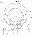
- 1 is the rotor rotating around a vertical machine axis in the direction of arrow A of a device designed as a rinser for treating bottles 2, which are fed to the device via a conveyor 3 and an inlet star 4 and which after treatment via an ejecting star and a conveyor 6 are discharged, on which the bottles 2 in turn upright, d. H. are led away with their bottom below.
- Each incoming bottle 2 is gripped and turned by a bottle gripper 7 provided on the rotor 1, so that the bottle bottom 21 finally points upwards and the bottle mouth 2 ′′ points downwards.
- This turning which takes place in a first angular range I following the inlet star 4, takes place in such a way that the respective bottle 2 is pivoted radially outward with its bottle bottom 2 '.
- the bottle 2 is treated in a further, subsequent angular range II.
- a subsequent angular range III of the rotary movement of the rotor 1 the respective bottle 2 is turned back into its original position and placed on the rotor 1.
- Curve 8 shown with a broken line, shows the vertical projection of the lower region of bottles 2 with rotating rotor 1.
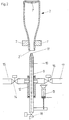
- each bottle gripper 7 is assigned a vertical nozzle tube 9 forming a treatment position.
- the nozzle tubes 9 are offset on the rotor 1 at equal angular intervals about its axis of rotation or are provided on an element (not shown) of the bottle gripper 7, so that each nozzle tube 9 is located below a bottle 2 that is gripped and turned by the associated bottle gripper 7, and in fact axially or approximately axially with the axis of the inverted bottle 2, as shown in FIG. 2.
- Each nozzle tube 9 has a nozzle channel 10 with an upper outlet or nozzle opening 11 and is displaceable in a bearing and distributor element 12 for a predetermined stroke in the vertical direction, specifically by an actuating element 13, which in the embodiment shown is formed by a pneumatic cylinder is.
- Each nozzle tube 9 is connected to a line 15 for warm water via the distributor element 12 and an individually controllable valve 14. Furthermore, each nozzle tube 9 is connected via the distributor element 12 and an individually controllable valve 18 to a line 17 for supplying steam.
- valve 2 shows at the lower end of the nozzle tube 9 a control valve 18 with which the respective nozzle tube 9 or the channel 10 there can be emptied.
- the valves 14, 16 and 18 are, for example, electrically or pneumatically operated valves.
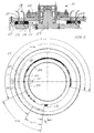
- FIG. 3 The actual design of the rotary valve 19 can be seen from FIG. 3.
- This consists of a stationary bearing part 20 with a central shaft 21 arranged thereon, which receives the upper part 22 of the rotary valve 19.
- This upper part has a multiplicity of bores 23 in which connecting hoses 24 to the individual nozzles 9 are received.
- the liquid-distributing disks 25, 26, 27 Between the upper part and the lower bearing part 20 are the liquid-distributing disks 25, 26, 27.
- the ring gears 25, 27 each have a toothing 30 on which a pinion 31 of an actuating device acts.
- a certain distance is provided for each channel 28, 29, which supplies the respective bores 23 with a certain amount of liquid. If, depending on the performance of the machine or the bottles to be treated, different amounts of media are to be discharged to the nozzles 9, a corresponding change in the media channel length is caused by motorized adjustment of a ring gear 25 or both ring gears 25, 27. For the media, you can adjust between a maximum and minimum channel length.
- the channels 28, 29 are equipped with openings, not shown, from which the medium from the bearing part 20 to the distributor disks or the channels 28, 29 and 32 arranged therein can be assigned.
- each media channel can be set separately from one another.
- the servomotor is also adjustable as a function of the speed of the rinser, so that the optimum amounts are passed to the nozzles 9 and thus to the bottles. This results in an optimal use of the media to be fed in relation to the desired cleaning and sterilizing effect.
Landscapes
- Engineering & Computer Science (AREA)
- Mechanical Engineering (AREA)
- Cleaning In General (AREA)
- Filling Of Jars Or Cans And Processes For Cleaning And Sealing Jars (AREA)
Abstract
Description
Die Erfindung bezieht sich auf ein Verfahren gemäß Oberbegriff Patentanspruch 1 - 3 sowie auf eine Vorrichtung gemäß Oberbegriff Patentanspruch 4.The invention relates to a method according to the preamble of claims 1-3 and to a device according to the preamble of
Verfahren sowie Vorrichtungen zur Überkopf-Behandlung von Flaschen sind in unterschiedlichsten Ausführungen bekannt. Bekannt ist insbesondere auch eine nach Art eines Rinsers ausgebildete Vorrichtung, bei der die Flaschengreifer an einem um eine vertikale Achse umlaufenden Maschinenteil bzw. Rotor vorgesehen sind und die von den Flaschengreifern erfaßten, zunächst mit ihrem Boden nach unten weisenden Flaschen durch radiales Schwenken nach außen gewendet werden, so daß sich die Flaschen nach dem Wenden mit der Flaschenmündung über einem eine Düsenöffnung bildenden Düsenrohr für das Behandlungsmedium befinden. Dieses Düsenrohr wird zumindest dann, wenn die Behandlung mit einem gas- oder dampfförmigen Behandlungsmedium erfolgt, durch die Flaschenmündung von unten her in den Innenraum der gewendeten Flasche eingeführt. Probleme ergeben sich oftmals in bezug auf die geforderte Keimfreiheit der behandelten Flaschen, und zwar speziell auch in bezug auf die Keimfreiheit der Flaschenmündung.Methods and devices for overhead treatment of bottles are known in a wide variety of designs. In particular, a device designed in the manner of a rinser is also known, in which the bottle grippers are provided on a machine part or rotor rotating around a vertical axis and the bottles gripped by the bottle grippers, initially turned with their bottoms downward, are turned outwards by radial pivoting are so that the bottles are after turning with the bottle mouth over a nozzle opening forming a nozzle tube for the treatment medium. This nozzle tube is inserted at least when the treatment with a gaseous or vaporous treatment medium takes place through the bottle mouth from below into the interior of the flipped bottle. Problems often arise with regard to the required sterility of the treated bottles, specifically also with regard to the sterility of the bottle mouth.
Bei einem Verfahren nach der DE A1 4229 580 erfolgt nach Beendigung wenigstens einer Behandlungsphase oder auf diese zeitlich folgend eine Beaufschlagung der Flaschenmündung der jeweiligen Flasche mit einem Strahl eines dampf- oder gasförmigen Mediums, und zwar aus einer Düsenöffnung, die mit Abstand der Flaschenmündung gegenüberliegend vorgesehen ist. Der aus der Düsenöffnung austretende Strahl läßt sich dabei so einstellen, daß er nicht, allenfalls nur ganz geringfügig in die jeweilige Flasche eintritt, aber an der Flaschenmündung eine radial nach außen und zumindest teilweise auch axial entlang der Außenfläche der Flasche verlaufende Strömung erzeugt. Ist das bei der Nachbehandlung verwendete Medium ein Sterilisationsmedium, z. B. Wasserdampf, so wird hiermit eine optimale Sterilisation der Flasche im Bereich der Flaschenmündung erreicht.In a method according to DE A1 4229 580, after the end of at least one treatment phase or after this, the bottle mouth of the respective bottle is exposed to a jet of a vaporous or gaseous medium, namely from a nozzle opening which is provided opposite the bottle mouth is. The jet emerging from the nozzle opening can be adjusted so that it does not, if at all only very slightly, enter the respective bottle, but at the bottle mouth produces a flow running radially outwards and at least partially also axially along the outer surface of the bottle. If the medium used in the aftertreatment is a sterilization medium, e.g. B. steam, so an optimal sterilization of the bottle is achieved in the area of the bottle mouth.
Das bei der Nachbehandlung verwendete Medium kann auch dazu dienen, an die Flaschenmündung gelangte Reste oder Tropfen eines flüssigen Behandlungsmediums (z. B. Wasser) zu entfernen oder zu verhindern, daß derartige Tropfen oder Reste in die Flasche gelangen. Diese Nachbehandlung, die mit dem Sterilisationsmedium (z. B. Wasserdampf) oder mit steriler Luft erfolgt, wird vor dem Zurückwenden und/oder beim Zurückwenden der Flasche in ihre urpsrüngliche Ausgangslage vorgenommen und verhindert somit, daß bei diesem Zurückwenden Reste eines Behandlungsmediums und mit diesem Keime in den Innenraum der Flasche gelangen. Die Medien werden bei diesen Rundläufermaschinen über Drehschieber zu den einzelnen Düsen geführt, wie aus der DE A1 3504 999 bekannt. Dabei sind die Medienzuströmwege festgelegt, so daß je nach Drehzahl der Rundläufermaschine unterschiedliche Zuströmmengen auftreten.The medium used in the aftertreatment can also serve to remove residues or drops of a liquid treatment medium (e.g. water) that have reached the bottle mouth or to prevent such drops or residues from getting into the bottle. This aftertreatment, which is carried out with the sterilization medium (e.g. steam) or with sterile air, is carried out before the bottle is turned back and / or when it is returned to its original starting position and thus prevents residues of a treatment medium and with this when it is turned back Germs get into the interior of the bottle. In these rotary machines, the media are guided to the individual nozzles via rotary valves, as is known from DE A1 3504 999. The media inflow paths are defined so that different inflow quantities occur depending on the speed of the rotary machine.
Der Erfindung liegt die Aufgabe zugrunde, die Zuströmmengen exakt zu definieren und unterschiedlichen Bedürfnissen anpassen zu können, wobei bei verschiedenen Behandlungsmedien auch deren Mengenverhältnis zueinander veränderbar sein soll.The invention is based on the object of being able to precisely define the inflow amounts and to be able to adapt them to different needs, the ratio of amounts to one another also being able to be changed in the case of different treatment media.
Diese Aufgabe wird bei einem Verfahren der eingangs genannten Art dadurch gelöst, daß die Behandlungsdauer zum Reinigen und/oder Sterilisieren während des Umlaufs der Flaschen in Abhängigkeit von dem gewählten Reinigungsprogramm veränderbar ist.This object is achieved in a method of the type mentioned at the outset in that the duration of treatment for cleaning and / or sterilizing during the circulation of the bottles can be changed as a function of the selected cleaning program.
In selbständiger Ausgestaltung wird ferner vorgeschlagen, daß die Behandlungsdauer beim Rinsen und/oder Sterilisieren jeweils einzeln einstellbar ist.In an independent embodiment, it is also proposed that the duration of treatment for rinsing and / or sterilizing can be set individually.
Eine dazu geeignete Vorrichtung gemäß Oberbegriff Anspruch 4 zeichnet sich dadurch aus, daß der wechselnde Öffnungsquerschnitt mindestens eines Kanals durch Verstellen eines Durchschieberteils veränderbar ist.A suitable device according to the preamble of
Mit dem erfindungsgemäß vorgeschlagenen Verfahren und der zu dessen Durchführung geeigneten Vorrichtung ist eine beliebige Anpassung an den häufig unterschiedlichen Bedürfnissen solcher Reinigungsvorgänge möglich. Insbesondere können die Spritz- oder Sterilisationsmengen exakt auf die vorgegebenen Bedürfnisse und Flaschen bzw. Flaschengrößen eingestellt werden.With the method proposed according to the invention and the device suitable for carrying it out, any adaptation to the often different needs of such cleaning processes is possible. In particular, the spray or sterilization quantities can be set exactly to the specified needs and bottles or bottle sizes.
Die Erfindung wird im folgenden anhand der Figuren an einem Ausführungsbeispiel erläutert. Es zeigen:
- Fig. 1 in sehr vereinfachter Darstellung und in Draufsicht eine Vorrichtung zum Behandeln von Flaschen in Form eines Rinsers umlaufender Bauart,
- Fig. 2 in vereinfachter Darstellung eine an einem Flaschengreifer gehaltene, gewendete Flasche sowie ein unter der Flasche angeordnetes Düsenrohr einer Behandlungsstation und
- Fig. 3 die Drehschieberausbildung.
- 1 in a very simplified representation and in plan view, a device for treating bottles in the form of a rinser rotating design,
- Fig. 2 in a simplified representation of a bottle held on a bottle gripper, inverted bottle and a nozzle tube arranged under the bottle of a treatment station and
- Fig. 3, the rotary slide training.
In den Figuren ist 1 der um eine vertikale Maschinenachse in Richtung des Pfeiles A umlaufende Rotor einer als Rinser ausgebildeten Vorrichtung zum Behandeln von Flaschen 2, die der Vorrichtung über einem Transporteur 3 und einem Einlaufstern 4 zugeführt werden und die nach dem Behandeln über einen Ausschubstern und einem Transporteur 6 abgeführt werden, auf dem die Flaschen 2 wiederum aufrechtstehend, d. h. mit ihrem Boden unten abgeführt werden.In the figures, 1 is the rotor rotating around a vertical machine axis in the direction of arrow A of a device designed as a rinser for treating
Jede einlaufende Flasche 2 wird von einem am Rotor 1 vorgesehenen Flaschengreifer 7 erfaßt und gewendet, so daß der Flaschenboden 21 schließlich nach oben und die Flaschenmündung 2'' nach unten weisen. Dieses Wenden, welches in einem ersten, auf den Einlaufstern 4 folgenden Winkelbereich I stattfindet, erfolgt so, daß die jeweilige Flasche 2 mit ihrem Flaschenboden 2' radial nach außen geschwenkt wird. Nach dem Wenden erfolgt in einem weiteren, anschließenden Winkelbereich II das Behandeln der Flasche 2. In einem anschließenden Winkelbereich III der Drehbewegung des Rotors 1 wird die jeweilige Flasche 2 in ihre ursprüngliche Lage zurückgewendet und auf den Rotor 1 abgestellt. Die mit einer unterbrochenen Linie wiedergegebene Kurve 8 zeigt die vertikale Projektion des unteren Bereichs der Flaschen 2 bei umlaufenden Rotor 1.Each
Bei der dargestellten Ausführungsform ist jedem Flaschengreifer 7 ein eine Behandlungsposition bildendes vertikales Düsenrohr 9 zugeordnet. Die Düsenrohre 9 sind am Rotor 1 in gleichen Winkelabständen um dessen Drehachse versetzt oder an einem nicht dargestellten Element des Flaschengreifers 7 vorgesehen, so daß sich jedes Düsenrohr 9 bei einer von dem zugehörigen Flaschengreifer 7 erfaßten und gewendeten Flasche 2 unterhalb dieser gewendeten Flasche befindet, und zwar achsgleich oder in etwa achsgleich mit der Achse der gewendeten Flasche 2, wie dies in der Fig. 2 dargestellt ist.In the embodiment shown, each
Jedes Düsenrohr 9 besitzt einen Düsenkanal 10 mit einer oberen Austritts- bzw. Düsenöffnung 11 und ist in einem Lager- und Verteilerelement 12 für einen vorgegebenen Hub in vertikaler Richtung verschiebbar, und zwar durch ein Betätigungselement 13, welches bei der dargestellten Ausführungsform von einem Pneumatikzylinder gebildet ist.Each
Über das Verteilerelement 12 und ein individuell steuerbares Ventil 14 ist jedes Düsenrohr 9 mit einer Leitung 15 für warmes Wasser verbunden. Weiterhin ist jedes Düsenrohr 9 über das Verteilerelement 12 und ein individuell steuerbares Ventil 18 mit einer Leitung 17 zum Zuführen von Dampf verbunden.Each
Die Fig. 2 zeigt am unteren Ende des Düsenrohres 9 ein Steuerventil 18, mit welchem das jeweilige Düsenrohr 9 bzw. der dortige Kanal 10 entleert werden kann. Die Ventile 14, 16 und 18 sind beispielsweise elektrisch oder pneumatisch betätigte Ventile.2 shows at the lower end of the nozzle tube 9 a
Aus Fig. 3 ist die eigentliche Ausbildung des Drehschiebers 19 erkennbar. Dieser besteht aus einem ortsfesten Lagerteil 20 mit einer daran angeordneten Zentralwelle 21, die das Oberteil 22 des Drehschiebers 19 aufnimmt. Dieses Oberteil weist eine Vielzahl von Bohrungen 23 auf, in denen Verbindungsschläuche 24 zu den einzelnen Düsen 9 aufgenommen sind. Zwischen dem Oberteil und dem unteren Lagerteil 20 befinden sich die die Flüssigkeit verteilenden Verteilerscheiben 25, 26, 27. Diese bestehen wiederum aus einer ortsfesten Scheibe 26 und je einem inneren und äußeren Hohlrad 25, 27, die jeweils an ihrer zur inneren Scheibe 26 weisenden Peripherie eigene Kanäle 28, 29 aufweisen, durch die die Flüssigkeit während des Umlaufs auf die Bohrungen 23 und Verbindungsschläuche 24 verteilt wird.The actual design of the
Ferner besitzen die Hohlräder 25, 27 je eine Verzahnung 30, an die ein Ritzel 31 einer Stellvorrichtung angreift. In der Ausgangsposition ist eine bestimmte Strecke für jeden Kanal 28, 29 vorgesehen, der die jeweiligen Bohrungen 23 mit einer bestimmten Flüssigkeitsmenge versorgt. Sollen nun je nach Leistung der Maschine bzw. den zu behandelnden Flaschen unterschiedliche Medienmengen zu den Düsen 9 abgeleitet werden, so wird durch motorische Verstellung eines Hohlrades 25 oder beider Hohlräder 25, 27 eine entsprechende Veränderung der Medienkanallänge verursacht. Für die Medien kann beliebig zwischen einer maximalen und minimalen Kanallänge verstellt werden. Die Kanäle 28, 29 sind mit nicht weiter dargestellten Öffnungen ausgestattet, aus denen das Medium von dem Lagerteil 20 zu den Verteilerscheiben bzw. den darin angeordneten Kanälen 28, 29 und 32 zugeordnet werden kann. Es ist vorgesehen, daß bei mehreren nebeneinander verlaufenden Kanalreihen 28, 29 jeder Medienkanal getrennt voneinander eingestellt werden kann. Der Stellmotor ist ferner in Abhängigkeit von der Drehzahl des Rinsers einstellbar, so daß jeweils die optimalen Mengen zu den Düsen 9 und damit zu den Flaschen geleitet werden. Hierdurch ergibt sich eine optimale Ausnutzung der zuzuführenden Medien im Verhältnis zu der gewünschten Reinigungs- und Sterilisationswirkung.Furthermore, the
Claims (9)
Applications Claiming Priority (2)
| Application Number | Priority Date | Filing Date | Title |
|---|---|---|---|
| DE19613267 | 1996-04-03 | ||
| DE19613267A DE19613267A1 (en) | 1996-04-03 | 1996-04-03 | Overhead treatment procedures |
Publications (3)
| Publication Number | Publication Date |
|---|---|
| EP0799652A2 true EP0799652A2 (en) | 1997-10-08 |
| EP0799652A3 EP0799652A3 (en) | 1998-08-12 |
| EP0799652B1 EP0799652B1 (en) | 2001-12-19 |
Family
ID=7790330
Family Applications (1)
| Application Number | Title | Priority Date | Filing Date |
|---|---|---|---|
| EP97102191A Expired - Lifetime EP0799652B1 (en) | 1996-04-03 | 1997-02-12 | Apparatus for the upside down treatment of bottles |
Country Status (3)
| Country | Link |
|---|---|
| EP (1) | EP0799652B1 (en) |
| BR (1) | BR9700485A (en) |
| DE (2) | DE19613267A1 (en) |
Cited By (4)
| Publication number | Priority date | Publication date | Assignee | Title |
|---|---|---|---|---|
| WO2005000488A1 (en) | 2003-06-30 | 2005-01-06 | Suntory Limited | Rotary rinser |
| ITTO20090837A1 (en) * | 2009-10-30 | 2011-04-30 | Sidel Spa Con Socio Unico | RINSING MACHINE FOR CONTAINER TREATMENT, BOTTLES IN PARTICULAR |
| CN112774746A (en) * | 2020-12-29 | 2021-05-11 | 深圳市天林智能科学仪器有限公司 | Automatic processing workstation of waste liquid in organic test vial |
| CN115739884A (en) * | 2022-10-25 | 2023-03-07 | 湖南洪康新材料科技有限公司 | Medicine bottle cleaning and sterilizing system |
Families Citing this family (2)
| Publication number | Priority date | Publication date | Assignee | Title |
|---|---|---|---|---|
| DE19909488A1 (en) * | 1999-03-04 | 2000-09-07 | Khs Masch & Anlagenbau Ag | Device for overhead handling of bottles, especially rinser; has grippers to transport bottle and nozzles to direct handling medium at bottle through electrode to balance charge on bottle |
| DE10010215A1 (en) * | 2000-03-02 | 2001-09-06 | Khs Masch & Anlagenbau Ag | Overhead processing device for bottles has spray nozzles movable between work and cleaning position across or perpendicular to movement of revolving support |
Citations (2)
| Publication number | Priority date | Publication date | Assignee | Title |
|---|---|---|---|---|
| DE3504999A1 (en) | 1984-03-26 | 1985-09-26 | Tekal s.r.l., Bergamo | Apparatus for washing and rinsing bottles |
| DE4229580A1 (en) | 1992-09-04 | 1994-03-10 | Seitz Enzinger Noll Masch | Method and device for overhead treatment of bottles |
Family Cites Families (6)
| Publication number | Priority date | Publication date | Assignee | Title |
|---|---|---|---|---|
| US2418691A (en) * | 1944-03-14 | 1947-04-08 | Owens Illinois Glass Co | Machine for emptying and washing containers |
| GB1456601A (en) * | 1974-04-11 | 1976-11-24 | Le T I Im Lensoveta | Variable size orifice valve plates |
| IT1214795B (en) * | 1984-11-07 | 1990-01-18 | Enomec Srl | KEEPING CONSTANT, EVEN TO THE UNIVERSAL CONVEYOR SUITABLE TO VARY OF THE SPEED OF REGIME, TO PERFORM DIFFERENT SEQUENCES DILE THE QUANTITY OF THE EVOLVING FLUIDS PREFIXED TECHNOLOGICAL OPERATIONS ADDED INSIDE EVERY SINGLE CONTAINER IN TRANSIT. |
| DE3503752A1 (en) * | 1985-02-05 | 1986-08-07 | Gerhard 7520 Bruchsal Bühler | Orifice-regulating valve |
| IT1259122B (en) * | 1992-06-30 | 1996-03-11 | ROTARY RINSING MACHINE PROVIDED WITH A CONTROL DEVICE AND DISTRIBUTION OF PRODUCTS FOR THE TREATMENT OF BOTTLES, JARS OR SIMILAR | |
| US5425385A (en) * | 1993-07-12 | 1995-06-20 | Pepsico. Inc. | Rotary washer spraying system |
-
1996
- 1996-04-03 DE DE19613267A patent/DE19613267A1/en not_active Withdrawn
-
1997
- 1997-02-12 EP EP97102191A patent/EP0799652B1/en not_active Expired - Lifetime
- 1997-02-12 DE DE59705838T patent/DE59705838D1/en not_active Expired - Lifetime
- 1997-04-02 BR BR9700485A patent/BR9700485A/en active Search and Examination
Patent Citations (2)
| Publication number | Priority date | Publication date | Assignee | Title |
|---|---|---|---|---|
| DE3504999A1 (en) | 1984-03-26 | 1985-09-26 | Tekal s.r.l., Bergamo | Apparatus for washing and rinsing bottles |
| DE4229580A1 (en) | 1992-09-04 | 1994-03-10 | Seitz Enzinger Noll Masch | Method and device for overhead treatment of bottles |
Cited By (7)
| Publication number | Priority date | Publication date | Assignee | Title |
|---|---|---|---|---|
| WO2005000488A1 (en) | 2003-06-30 | 2005-01-06 | Suntory Limited | Rotary rinser |
| EP1642656A1 (en) * | 2003-06-30 | 2006-04-05 | Suntory Limited | Rotary rinser |
| EP1642656A4 (en) * | 2003-06-30 | 2011-03-02 | Suntory Holdings Ltd | Rotary rinser |
| ITTO20090837A1 (en) * | 2009-10-30 | 2011-04-30 | Sidel Spa Con Socio Unico | RINSING MACHINE FOR CONTAINER TREATMENT, BOTTLES IN PARTICULAR |
| CN112774746A (en) * | 2020-12-29 | 2021-05-11 | 深圳市天林智能科学仪器有限公司 | Automatic processing workstation of waste liquid in organic test vial |
| CN112774746B (en) * | 2020-12-29 | 2022-11-15 | 深圳市天林智能科学仪器有限公司 | Automatic processing workstation of waste liquid in organic test vial |
| CN115739884A (en) * | 2022-10-25 | 2023-03-07 | 湖南洪康新材料科技有限公司 | Medicine bottle cleaning and sterilizing system |
Also Published As
| Publication number | Publication date |
|---|---|
| EP0799652A3 (en) | 1998-08-12 |
| DE19613267A1 (en) | 1997-10-09 |
| DE59705838D1 (en) | 2002-01-31 |
| BR9700485A (en) | 1998-11-03 |
| EP0799652B1 (en) | 2001-12-19 |
Similar Documents
| Publication | Publication Date | Title |
|---|---|---|
| EP2035303B1 (en) | Method for handling containers and container handling machine | |
| EP2307303B1 (en) | Transport section for conveying caps or similar closures for closing bottles or similar containers | |
| EP2097184B1 (en) | Spraying station of a cleaning machine for bottles or similar containers, and cleaning machine comprising at least one spraying station | |
| EP0303135B1 (en) | Method for filling containers with liquids in an aseptic or sterile way, and apparatus for carrying out this method | |
| EP2059352B1 (en) | Method for treating bottles or such like containers in a cleaning machine and also cleaning machine | |
| DE3301525C2 (en) | ||
| EP1820731B1 (en) | Method for sterilising bottles or similar containers and device for performing this method | |
| DE102009033809A1 (en) | Device for treating containers with carrier sterilization | |
| EP0897864A2 (en) | Apparatus and method for the dosed filling of liquid to pasty products | |
| DE3918504C2 (en) | Sealing machine of all-round design | |
| EP2665676A1 (en) | Filling element comprising a spray nozzle or spray nozzle assembly, container treatment machine comprising a spray nozzle or spray nozzle assembly and method for cleaning machine elements | |
| EP0588134B1 (en) | Method and device for the cleaning of inverted bottles | |
| EP2332845A2 (en) | Labelling device and labelling method for labelling containers with sterilisation device | |
| EP0799652B1 (en) | Apparatus for the upside down treatment of bottles | |
| EP3798193A1 (en) | Device for coating containers with bypass and method for operating such a device | |
| EP1354799B1 (en) | Apparatus for treating packaging containers | |
| EP1048365B1 (en) | Method and device for the cleaning of inverted bottles | |
| DE19735621A1 (en) | Aseptic dessert filling machine has two discharge outlets to a single head | |
| EP1129794B1 (en) | Method for the upside down treatment of bottles or similar containers | |
| DE29903939U1 (en) | Device for overhead treatment of bottles | |
| DE4226616C2 (en) | Device for treating containers before filling | |
| DE10012909A1 (en) | Machine bottle cleaning process involves cleaning bottles in cleaning machine and sending without water spray to rinser for overhead treatment | |
| DE29803902U1 (en) | Device for overhead treatment of bottles | |
| DE102008059431A1 (en) | Apparatus and method for treating bottles or similar containers | |
| DE9311106U1 (en) | Plant for the sterile filling and closing of bottles or the like. container |
Legal Events
| Date | Code | Title | Description |
|---|---|---|---|
| PUAI | Public reference made under article 153(3) epc to a published international application that has entered the european phase |
Free format text: ORIGINAL CODE: 0009012 |
|
| AK | Designated contracting states |
Kind code of ref document: A2 Designated state(s): DE FR GB IT NL |
|
| PUAL | Search report despatched |
Free format text: ORIGINAL CODE: 0009013 |
|
| AK | Designated contracting states |
Kind code of ref document: A3 Designated state(s): DE FR GB IT NL |
|
| 17P | Request for examination filed |
Effective date: 19980902 |
|
| 17Q | First examination report despatched |
Effective date: 20000522 |
|
| RTI1 | Title (correction) |
Free format text: APPARATUS FOR THE UPSIDE DOWN TREATMENT OF BOTTLES |
|
| GRAG | Despatch of communication of intention to grant |
Free format text: ORIGINAL CODE: EPIDOS AGRA |
|
| GRAG | Despatch of communication of intention to grant |
Free format text: ORIGINAL CODE: EPIDOS AGRA |
|
| GRAH | Despatch of communication of intention to grant a patent |
Free format text: ORIGINAL CODE: EPIDOS IGRA |
|
| GRAH | Despatch of communication of intention to grant a patent |
Free format text: ORIGINAL CODE: EPIDOS IGRA |
|
| ITF | It: translation for a ep patent filed | ||
| GRAA | (expected) grant |
Free format text: ORIGINAL CODE: 0009210 |
|
| AK | Designated contracting states |
Kind code of ref document: B1 Designated state(s): DE FR GB IT NL |
|
| REG | Reference to a national code |
Ref country code: GB Ref legal event code: IF02 |
|
| GBT | Gb: translation of ep patent filed (gb section 77(6)(a)/1977) |
Effective date: 20011231 |
|
| REF | Corresponds to: |
Ref document number: 59705838 Country of ref document: DE Date of ref document: 20020131 |
|
| ET | Fr: translation filed | ||
| PLBE | No opposition filed within time limit |
Free format text: ORIGINAL CODE: 0009261 |
|
| STAA | Information on the status of an ep patent application or granted ep patent |
Free format text: STATUS: NO OPPOSITION FILED WITHIN TIME LIMIT |
|
| 26N | No opposition filed | ||
| REG | Reference to a national code |
Ref country code: NL Ref legal event code: TD Effective date: 20111114 |
|
| REG | Reference to a national code |
Ref country code: FR Ref legal event code: CD Owner name: KHS GMBH Effective date: 20111122 Ref country code: FR Ref legal event code: CD Owner name: KHS GMBH Effective date: 20111121 |
|
| REG | Reference to a national code |
Ref country code: FR Ref legal event code: PLFP Year of fee payment: 20 |
|
| PGFP | Annual fee paid to national office [announced via postgrant information from national office to epo] |
Ref country code: IT Payment date: 20160223 Year of fee payment: 20 Ref country code: DE Payment date: 20160218 Year of fee payment: 20 |
|
| PGFP | Annual fee paid to national office [announced via postgrant information from national office to epo] |
Ref country code: GB Payment date: 20160217 Year of fee payment: 20 Ref country code: FR Payment date: 20160218 Year of fee payment: 20 Ref country code: NL Payment date: 20160217 Year of fee payment: 20 |
|
| REG | Reference to a national code |
Ref country code: DE Ref legal event code: R071 Ref document number: 59705838 Country of ref document: DE |
|
| REG | Reference to a national code |
Ref country code: NL Ref legal event code: MK Effective date: 20170211 |
|
| REG | Reference to a national code |
Ref country code: GB Ref legal event code: PE20 Expiry date: 20170211 |
|
| PG25 | Lapsed in a contracting state [announced via postgrant information from national office to epo] |
Ref country code: GB Free format text: LAPSE BECAUSE OF EXPIRATION OF PROTECTION Effective date: 20170211 |