EP0798477A1 - Betätigungszug - Google Patents
Betätigungszug Download PDFInfo
- Publication number
- EP0798477A1 EP0798477A1 EP97103508A EP97103508A EP0798477A1 EP 0798477 A1 EP0798477 A1 EP 0798477A1 EP 97103508 A EP97103508 A EP 97103508A EP 97103508 A EP97103508 A EP 97103508A EP 0798477 A1 EP0798477 A1 EP 0798477A1
- Authority
- EP
- European Patent Office
- Prior art keywords
- cable according
- actuating cable
- actuating
- filler
- inner tube
- Prior art date
- Legal status (The legal status is an assumption and is not a legal conclusion. Google has not performed a legal analysis and makes no representation as to the accuracy of the status listed.)
- Withdrawn
Links
- 239000004734 Polyphenylene sulfide Substances 0.000 claims abstract description 14
- 229920000069 polyphenylene sulfide Polymers 0.000 claims abstract description 14
- 239000004033 plastic Substances 0.000 claims abstract description 13
- 229920003023 plastic Polymers 0.000 claims abstract description 13
- -1 polyacrylimide Polymers 0.000 claims abstract description 11
- 229920001230 polyarylate Polymers 0.000 claims abstract description 4
- 229920000106 Liquid crystal polymer Polymers 0.000 claims abstract description 3
- 239000004697 Polyetherimide Substances 0.000 claims abstract description 3
- 229920001643 poly(ether ketone) Polymers 0.000 claims abstract description 3
- 229920002492 poly(sulfone) Polymers 0.000 claims abstract description 3
- 229920001601 polyetherimide Polymers 0.000 claims abstract description 3
- BFKJFAAPBSQJPD-UHFFFAOYSA-N tetrafluoroethene Chemical group FC(F)=C(F)F BFKJFAAPBSQJPD-UHFFFAOYSA-N 0.000 claims abstract description 3
- 239000000945 filler Substances 0.000 claims description 15
- 239000011521 glass Substances 0.000 claims description 10
- 229920001343 polytetrafluoroethylene Polymers 0.000 claims description 6
- 239000004810 polytetrafluoroethylene Substances 0.000 claims description 6
- OKTJSMMVPCPJKN-UHFFFAOYSA-N Carbon Chemical group [C] OKTJSMMVPCPJKN-UHFFFAOYSA-N 0.000 claims description 5
- 230000006835 compression Effects 0.000 claims description 5
- 238000007906 compression Methods 0.000 claims description 5
- 230000002787 reinforcement Effects 0.000 claims description 5
- RTAQQCXQSZGOHL-UHFFFAOYSA-N Titanium Chemical compound [Ti] RTAQQCXQSZGOHL-UHFFFAOYSA-N 0.000 claims description 4
- 229910052799 carbon Inorganic materials 0.000 claims description 4
- 238000005299 abrasion Methods 0.000 claims description 3
- 239000002184 metal Substances 0.000 claims description 3
- 239000002245 particle Substances 0.000 claims 1
- 239000000463 material Substances 0.000 description 8
- 229910000831 Steel Inorganic materials 0.000 description 4
- 239000000835 fiber Substances 0.000 description 4
- 239000010959 steel Substances 0.000 description 4
- 239000004696 Poly ether ether ketone Substances 0.000 description 3
- 230000005540 biological transmission Effects 0.000 description 3
- 229920002530 polyetherether ketone Polymers 0.000 description 3
- 229920000049 Carbon (fiber) Polymers 0.000 description 2
- 239000004695 Polyether sulfone Substances 0.000 description 2
- 239000004917 carbon fiber Substances 0.000 description 2
- 238000010276 construction Methods 0.000 description 2
- 238000005516 engineering process Methods 0.000 description 2
- 239000003365 glass fiber Substances 0.000 description 2
- 229920006393 polyether sulfone Polymers 0.000 description 2
- 229920000139 polyethylene terephthalate Polymers 0.000 description 2
- 239000005020 polyethylene terephthalate Substances 0.000 description 2
- 229910001335 Galvanized steel Inorganic materials 0.000 description 1
- 239000004952 Polyamide Substances 0.000 description 1
- 239000004698 Polyethylene Substances 0.000 description 1
- 239000004642 Polyimide Substances 0.000 description 1
- 239000004743 Polypropylene Substances 0.000 description 1
- 238000004378 air conditioning Methods 0.000 description 1
- 239000004760 aramid Substances 0.000 description 1
- 229920003235 aromatic polyamide Polymers 0.000 description 1
- 238000005253 cladding Methods 0.000 description 1
- 239000003245 coal Substances 0.000 description 1
- 239000011248 coating agent Substances 0.000 description 1
- 238000000576 coating method Methods 0.000 description 1
- 230000000694 effects Effects 0.000 description 1
- 238000002474 experimental method Methods 0.000 description 1
- 230000002349 favourable effect Effects 0.000 description 1
- 239000002783 friction material Substances 0.000 description 1
- 239000000446 fuel Substances 0.000 description 1
- 239000008397 galvanized steel Substances 0.000 description 1
- 229910002804 graphite Inorganic materials 0.000 description 1
- 239000010439 graphite Substances 0.000 description 1
- 238000010438 heat treatment Methods 0.000 description 1
- VNWKTOKETHGBQD-UHFFFAOYSA-N methane Chemical compound C VNWKTOKETHGBQD-UHFFFAOYSA-N 0.000 description 1
- 239000000088 plastic resin Substances 0.000 description 1
- 229920002647 polyamide Polymers 0.000 description 1
- 239000004417 polycarbonate Substances 0.000 description 1
- 229920000515 polycarbonate Polymers 0.000 description 1
- 229920000573 polyethylene Polymers 0.000 description 1
- 229920001721 polyimide Polymers 0.000 description 1
- 229920001155 polypropylene Polymers 0.000 description 1
- 229920000915 polyvinyl chloride Polymers 0.000 description 1
- 239000004800 polyvinyl chloride Substances 0.000 description 1
- 239000007787 solid Substances 0.000 description 1
- 229920005992 thermoplastic resin Polymers 0.000 description 1
Images
Classifications
-
- F—MECHANICAL ENGINEERING; LIGHTING; HEATING; WEAPONS; BLASTING
- F16—ENGINEERING ELEMENTS AND UNITS; GENERAL MEASURES FOR PRODUCING AND MAINTAINING EFFECTIVE FUNCTIONING OF MACHINES OR INSTALLATIONS; THERMAL INSULATION IN GENERAL
- F16C—SHAFTS; FLEXIBLE SHAFTS; ELEMENTS OR CRANKSHAFT MECHANISMS; ROTARY BODIES OTHER THAN GEARING ELEMENTS; BEARINGS
- F16C1/00—Flexible shafts; Mechanical means for transmitting movement in a flexible sheathing
- F16C1/26—Construction of guiding-sheathings or guiding-tubes
-
- Y—GENERAL TAGGING OF NEW TECHNOLOGICAL DEVELOPMENTS; GENERAL TAGGING OF CROSS-SECTIONAL TECHNOLOGIES SPANNING OVER SEVERAL SECTIONS OF THE IPC; TECHNICAL SUBJECTS COVERED BY FORMER USPC CROSS-REFERENCE ART COLLECTIONS [XRACs] AND DIGESTS
- Y10—TECHNICAL SUBJECTS COVERED BY FORMER USPC
- Y10T—TECHNICAL SUBJECTS COVERED BY FORMER US CLASSIFICATION
- Y10T428/00—Stock material or miscellaneous articles
- Y10T428/29—Coated or structually defined flake, particle, cell, strand, strand portion, rod, filament, macroscopic fiber or mass thereof
- Y10T428/2913—Rod, strand, filament or fiber
- Y10T428/2927—Rod, strand, filament or fiber including structurally defined particulate matter
-
- Y—GENERAL TAGGING OF NEW TECHNOLOGICAL DEVELOPMENTS; GENERAL TAGGING OF CROSS-SECTIONAL TECHNOLOGIES SPANNING OVER SEVERAL SECTIONS OF THE IPC; TECHNICAL SUBJECTS COVERED BY FORMER USPC CROSS-REFERENCE ART COLLECTIONS [XRACs] AND DIGESTS
- Y10—TECHNICAL SUBJECTS COVERED BY FORMER USPC
- Y10T—TECHNICAL SUBJECTS COVERED BY FORMER US CLASSIFICATION
- Y10T428/00—Stock material or miscellaneous articles
- Y10T428/29—Coated or structually defined flake, particle, cell, strand, strand portion, rod, filament, macroscopic fiber or mass thereof
- Y10T428/2913—Rod, strand, filament or fiber
- Y10T428/2933—Coated or with bond, impregnation or core
- Y10T428/2936—Wound or wrapped core or coating [i.e., spiral or helical]
-
- Y—GENERAL TAGGING OF NEW TECHNOLOGICAL DEVELOPMENTS; GENERAL TAGGING OF CROSS-SECTIONAL TECHNOLOGIES SPANNING OVER SEVERAL SECTIONS OF THE IPC; TECHNICAL SUBJECTS COVERED BY FORMER USPC CROSS-REFERENCE ART COLLECTIONS [XRACs] AND DIGESTS
- Y10—TECHNICAL SUBJECTS COVERED BY FORMER USPC
- Y10T—TECHNICAL SUBJECTS COVERED BY FORMER US CLASSIFICATION
- Y10T428/00—Stock material or miscellaneous articles
- Y10T428/29—Coated or structually defined flake, particle, cell, strand, strand portion, rod, filament, macroscopic fiber or mass thereof
- Y10T428/2913—Rod, strand, filament or fiber
- Y10T428/2933—Coated or with bond, impregnation or core
- Y10T428/294—Coated or with bond, impregnation or core including metal or compound thereof [excluding glass, ceramic and asbestos]
- Y10T428/2942—Plural coatings
- Y10T428/2947—Synthetic resin or polymer in plural coatings, each of different type
Definitions
- the invention relates to an actuating cable in particular for the actuation of bicycle brakes with a guide tube and an actuating core axially movable therein, the guide tube having an inner tube and a jacket tube surrounding it.
- Actuating cables of the aforementioned type are proven and inexpensive construction elements for the transmission of forces from an actuating member to an actuating member, in particular when the power transmission cannot take place in a straight line. They are used in many areas of technology (cf. Leiseder, Ludwig M., Mechanical actuation trains, Verlag Moderne Industrie, Landsberg / Lech, 1994), in particular in the area of vehicle technology. In bicycles, they are used to operate the brakes, i.e. to transmit the manual force exerted on the brake hand levers to the brake calipers.
- actuation cables particularly with regard to the construction of the guide hose.
- the structure is essentially based on the forces to be transferred. It is known to have the guide hoses made exclusively of plastic, the guide hose also being able to be constructed with two shells, ie from an inner hose and a jacket hose (DE-U-1 880-165). Polyvinyl chloride or polyethylene are proposed as materials for the jacket tube and polyamide for the inner tube.
- actuation cables are due to the relatively low strength and stiffness are only used where the forces to be transmitted are low, such as for operating heating and air-conditioning systems, for operating the door and door and for unlocking the fuel filler cap (see also pages 28 and 29).
- actuation cables are known in which the guide tube consists of fiber-reinforced thermoplastic resin.
- Polyether ether ketone, polyether sulfone, polyethylene terephthalate, polyarylate, polyphenylene sulfide, polyimide, polycarbonate and polyethylene terephthalate are specified as the plastic resin.
- Glass or carbon fibers as well as aromatic polyamide fibers and steel fibers are proposed as fiber reinforcements.
- the operating cable has the disadvantage that the efficiency is not satisfactory.
- the invention has for its object to form an actuating cable of the type mentioned so that it has a high Efficiency and light weight and ensures precise operation.
- the inner tube consists at least mainly of a polymerized tetrafluoroethylene, in particular polytetrafluoroethylene
- the jacket tube consists at least mainly of a high-performance plastic with high mechanical strength and rigidity, namely from a polyarylate, polyacrylimide, polyetherimide, polysulfone, in particular polyether sulfone, Polyphenylene sulfide, polyether ketone, in particular polyether ether ketone and / or liquid-crystalline polymer and / or a plastic, the strength and stiffness of which is in the range of the strengths and stiffness of the above plastics.
- the actuating jacket should not contain any metal reinforcement. However, fiber reinforcement made of glass or carbon fiber, for example, can be favorable.
- the basic idea of the invention is to carry out a type of function division.
- the inner tube is made of a very low-friction material that is highly efficient, i.e. H. extensive transmission of the forces applied to the brake is guaranteed.
- the jacket hose absorbs the compression forces and is therefore made of a high-performance plastic with excellent mechanical properties.
- the division of functions makes it possible to use optimal materials for the respective function.
- the inner tube contains a filler which improves its abrasion resistance.
- Carbon may be used as fillers, for example in the form of coal or graphite, glass, titanate and / or polyphenylene sulfide.
- the filler should be present at least in the region of the inner surface, preferably over the entire cross section of the inner tube, in a content of 5 to 12% by weight, the combination of polyphenylene sulfide and glass being particularly advantageous.
- the polyphenylene sulfide should be present at least in the area of the inner surface with a content of 4 to 8% by weight, the rest being glass and polytetrafluoroethylene, and the proportion of glass should not exceed 50% of the proportion of polyphenylene sulfide.
- the cladding layer contains a filler which improves the pressure rigidity.
- the filler can be carbon, glass, titanate and / or polyphenylene sulfide. The addition of such fillers reduces elasticity and leads to even more precise actuation.
- the actuating core is preferably designed as a wire strand with a smooth and non-plastic-coated surface. It has been shown that such a surface is a good friction partner for the material of the inner tube.
- the wire strand should preferably have a circular cross section.
- the jacket tube and the inner tube are anchored to one another in a positive manner in the axial direction. This can be done by means of projections or recesses on the contact surface between the jacket tube and the inner tube.
- recesses can be formed in the outside of the inner tube and the jacket tube can be injected over the inner tube, so that the material of the jacket tube flows into the recesses.
- the inner tube has a helical groove and / or a helical web on the outside and grips the jacket hose into the groove or the web.
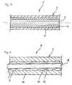
- FIG. 1 shows a section of an actuating cable 1, which consists of a guide hose 2 and an actuating wire 3. It cannot be seen that the ends of the guide hose 2 are provided with connecting means by means of which they can be fixed on the brake actuation device and in the area of the brake caliper.
- the actuating wire 3 has elements at the end via which it can be connected to the actuating member, in this case the brake lever on the steering wheel of a bicycle, and to the member to be actuated, namely the brake caliper.
- the guide tube 2 is constructed with two shells. It consists of an inner tube 4 and a jacket tube 5 surrounding it, both tubes 4, 5 being firmly connected to one another, for example by extruding the jacket tube 5 onto the inner tube 4.
- the inner tube 4 consists of polytetrafluoroethylene, in which a filler is embedded, which improves the abrasion resistance of the PTFE.
- the jacket hose 5 consists of polyether ether ketone, which is characterized by high mechanical strength and rigidity. The jacket hose 5 thus serves to absorb the upset forces that occur when the force is exerted on the actuating wire 3. The smallest possible change in length in the compression of the guide tube 2 is aimed for.
- the operating wire 3 is calibrated, ie it is smooth on the outside like a solid wire.
- the individual wires can only be seen in cross-section.
- the smooth metal surface together with the excellent sliding properties of PTFE, it ensures low frictional resistance and thus high efficiency.
- the total weight is low because of the exclusive use of plastic for the guide tube 2.
- FIG. 2 shows an actuating cable 6 with a guide tube 7 and an operating wire 8.
- the guide tube 7 is constructed with two shells and consists of an inner tube 9 and a jacket tube 10 'surrounding it.
- the materials correspond to the materials described for the actuating hose 1 according to FIG. 1.
- the outside of the inner tube has 9 projections - designated 11 by way of example. They have been produced in that the inner tube 9 is first formed on the top and bottom with a longitudinal web, which has then been removed at certain intervals with the aid of a cutting tool, so that a change of projections 11 and recesses 12 can be seen in the longitudinal direction on the top and bottom of the inner tube 9 results. Then the jacket hose 10sch was extruded so that its material could be stored in the recesses 12. In this way, a firm connection between inner tube 9 and jacket tube 10 ⁇ is made in the axial direction.
Landscapes
- Engineering & Computer Science (AREA)
- General Engineering & Computer Science (AREA)
- Health & Medical Sciences (AREA)
- Oral & Maxillofacial Surgery (AREA)
- Mechanical Engineering (AREA)
- Flexible Shafts (AREA)
- Ropes Or Cables (AREA)
- Resistance Heating (AREA)
- Rigid Pipes And Flexible Pipes (AREA)
Abstract
Ein Betätigungszug (1, 6) insbesondere für die Betätigung von Fahrradbremsen weist einen Führungsschlauch (2, 7) und eine darin axial bewegliche Betätigungsseele (3, 8) auf, wobei der Führungsschlauch (2, 7) einen Innenschlauch (4, 9) und einen diesen umgebenden Mantelschlauch (5, 1Ø) hat. Der Innenschlauch (4, 9) besteht wenigstens hauptsächlich aus einem polymerisierten Tetrafluorethylen und der Mantelschlauch wenigstens hauptsächlich aus einem Polyarylat, Polyacrylimid, Polyetherimid, Polysulfon, Polyphenylensulfid, Polyetherketon und/oder flüssigkristallinem Polymer und/oder einem Kunststoff, dessen Steifheit und Festigkeit in dem Bereich der Steifheiten und Festigkeiten vorstehender Kunststoffe liegt. <IMAGE>
Description
- Die Erfindung betrifft einen Betätigungszug insbesondere für die Betätigung von Fahrradbremsen mit einem Führungsschlauch und einer darin axial beweglichen Betätigungsseele, wobei der Führungsschlauch einen Innenschlauch und einen diesen umgebenden Mantelschlauch aufweist.
- Betätigungszüge der vorgenannten Art sind bewährte und preiswerte Konstruktionselemente für die Übertragung von Kräften von einem Betätigungsorgan zu einem zu betätigenden Organ, und zwar insbesondere dann, wenn die Kraftübertragung nicht auf geradem Weg erfolgen kann. Sie werden auf vielen Gebieten der Technik angewendet (vgl. Leiseder, Ludwig M., Mechanische Betätigungszüge, Verlag Moderne Industrie, Landsberg/Lech, 1994), insbesondere auf dem Gebiet der Fahrzeugtechnik. Bei Fahrrädern dienen sie der Bremsenbetätigung, also der Übertragung der auf die Bremshandhebel ausgeübten Handkraft auf die Bremszangen.
- Aus dem vorzitierten Buch ergibt sich, daß es Betätigungszüge in vielfältigen Ausführungsformen gibt, insbesondere was den Aufbau des Führungsschlauchs angeht. Dabei orientiert sich der Aufbau im wesentlichen an den zu übertragenden Kräften. So ist es bekannt, die Führungsschläuche ausschließlich aus Kunststoff bestehen zu lassen, wobei der Führungsschlauch auch zweischalig, d. h. aus einem Innenschlauch und einem Mantelschlauch, aufgebaut sein kann (DE-U-1 880̸ 165). Dabei werden als Materialien für den Mantelschlauch Polyvinylchlorid oder Polyethylen und für den Innenschlauch Polyamid vorgeschlagen. Allerdings werden solche Betätigungszüge wegen der relativ geringen Festigkeit und Steifigkeit nur dort eingesetzt, wo die zu übertragenden Kräfte gering sind, wie beispielsweise zur Betätigung von Heizungs- und Klimaeinrichtungen, als Türinnen- und Türaußenbetätigung und als Tankdeckelentriegelung (vgl. a.a.O. Seiten 28 und 29).
- Bei der Verwendung zur Bremsenbetätigung an Fahrrädern sind die zu übertragenden Kräfte relativ hoch, so daß auf den Führungsschlauch entsprechend hohe Stauchkräfte wirken. Bei den bekannten Betätigungszügen wird deshalb nicht auf eine Stahldrahtarmierung, beispielsweise in Form einer kunststoffummantelten Stahlspirale, verzichtet. Dabei wird innenseitig ein anderer Kunststoff als außenseitig verwendet. Als Betätigungsseele kommt eine verzinkte Stahllitze zum Einsatz, die zwecks Vermeidung des Sägeeffekts an der Innenseite des Führungsschlauchs mit einem Polypropylen-Überzug versehen ist.
- Da das Fahrrad zunehmend als Sportgerät eingesetzt wird, und zwar nicht nur als Rennrad, sondern auch als sogenanntes Mountain-Bike, werden hohe Anforderungen an den Wirkungsgrad und das Gewicht solcher Betätigungszüge gestellt. Die bekannten Betätigungszüge sind relativ schwer, und der Wirkungsgrad sowie die Exaktheit ist immer noch verbesserungsbedürftig.
- Daneben sind Betätigungszüge bekannt, bei denen der Führungsschlauch aus faserverstärktem thermoplastischem Kunststoffharz besteht. Als Kunststoffharz werden angegeben Polyetheretherketon, Polyethersulfon, Polyethylentelephtalat, Polyarylat, Polyphenylensulfid, Polyimid, Polycarbonat und Polyethylentelephtalat. Als Faserverstärkungen werden Glas- oder Kohlefasern sowie aromatische Polyamidfasern und Stahlfasern vorgeschlagen. Der Betätigungszug hat den Nachteil, daß der Wirkungsgrad nicht befriedigt.
- Der Erfindung liegt die Aufgabe zugrunde, einen Betätigungszug der eingangs genannten Art so auszubilden, daß er einen hohen Wirkungsgrad und ein geringes Gewicht hat und eine exakte Betätigung gewährleistet.
- Diese Aufgabe wird erfindungsgemäß dadurch gelöst, daß der Innenschlauch wenigstens hauptsächlich aus einem polymerisierten Tetrafluorethylen, insbesondere Polytetrafluorethylen, und der Mantelschlauch wenigstens hauptsächlich aus einem Hochleistungskunststoff mit hoher mechanischer Festigkeit und Steifheit besteht, nämlich aus einem Polyarylat, Polyacrylimid, Polyetherimid, Polysulfon, insbesondere Polyethersulfon, Polyphenylensulfid, Polyetherketon, insbesondere Polyetheretherketon und/oder flüssigkristallinem Polymer und/oder einem Kunststoff besteht, dessen Festigkeit und Steifheit in dem Bereich der Festigkeiten und Steifheiten vorstehender Kunststoffe liegt. Dabei sollte der Betätigungsmantel keine Metallarmierung enthalten. Günstig kann jedoch eine Faserarmierung beispielsweise aus Glas- oder Kohlefaser sein.
- Grundgedanke der Erfindung ist es, eine Art Funktionsteilung vorzunehmen. Der Innenschlauch besteht aus einem sehr reibungsarmen Material, das einen hohen Wirkungsgrad, d. h. eine weitgehende Übertragung der eingeleiteten Kräfte auf die Bremse, gewährleistet. Der Mantel schlauch dient der Aufnahme der Stauchkräfte und ist deshalb aus einem Hochleistungskunststoff mit herausragenden mechanischen Eigenschaften hergestellt. Die Funktionsteilung ermöglicht es, für die jeweilige Funktion optimale Materialien zu verwenden.
- Versuche haben gezeigt, daß ein solcher Betätigungszug in der Lage ist, selbst höchste Stauchkräfte ohne Beschädigung aufzunehmen und gleichzeitig einen bisher nicht erreichten Wirkungsgrad zu erreichen. Die für den Mantelschlauch vorgesehenen Materialien machen eine Stahlarmierung entbehrlich und sorgen so für sehr geringes Gewicht.
- In Ausbildung der Erfindung ist vorgesehen, daß der Innenschlauch einen dessen Abriebfestigkeit verbessernden Füllstoff enthält. Dabei kommen als Füllstoffe Kohlenstoff, beispielsweise in Form von Kohle oder Graphit, Glas, Titanat und/oder Polyphenylensulfid in Frage. Der Füllstoff sollte wenigstens im Bereich der Innenoberfläche, vorzugsweise über den gesamten Querschnitt des Innenschlauchs mit einein Gehalt von 5 bis 12 Gew.-% vorliegen, wobei die Kombination von Polyphenylensulfid und Glas besonders vorteilhaft ist. In diesem Fall sollte das Polyphenylensulfid wenigstens im Bereich der Innenoberfläche mit einem Gehalt von 4 bis 8 Gew.-%, Rest Glas und Polytetrafluorethylen, vorliegen und dabei der Anteil von Glas höchstens 50̸ % des Anteils Polyphenylensulfid betragen.
- Nach einem weiteren Merkmal der Erfindung ist vorgesehen, daß die Mantelschicht einen die Drucksteifigkeit verbessernden Füllstoff enthält. Auch in diesem Fall kann der Füllstoff Kohlenstoff, Glas, Titanat und/oder Polyphenylensulfid sein. Der Zusatz solcher Füllstoffe verringert die Elastizität und führt zu einer noch exakteren Betätigung.
- Die Betätigungsseele ist vorzugsweise als Drahtlitze mit geglätteter und nicht kunststoffummantelter Oberfläche ausgebildet. Es hat sich gezeigt, daß eine solche Oberfläche ein guter Reibungspartner für das Material des Innenschlauchs ist. Vorzugsweise sollte die Drahtlitze kreisrunden Querschnitt haben.
- Nach einem weiteren Merkmal der Erfindung ist vorgesehen, daß Mantelschlauch und Innenschlauch in axialer Richtung miteinander formschlüssig verankert sind. Dies kann durch Vorsprünge oder Ausnehmungen an der Berührungsfläche zwischen Mantelschlauch und Innenschlauch geschehen. Insbesondere können Ausnehmungen in die Außenseite des Innenschlauchs eingeformt und der Mantelschlauch über den Innenschlauch gespritzt werden, so daß das Material des Mantelschlauchs in die Ausnehmungen einfließt. In Sonderheit weist der Innenschlauch außenseitig eine schraubenförmige Nut und/oder einen schraubenförmigen Steg auf und faßt der Mantelschlauch in die Nut bzw. den Steg ein.
- In der Zeichnung ist die Erfindung anhand von zwei Ausführungsbeispielen näher veranschaulicht. Es zeigen:
- Figur 1
- einen Betätigungszug im Längsschnitt und
- Figur 2
- einen zweiten Betätigungszug im Längsschnitt.
- Figur 1 zeigt einen Abschnitt eines Betätigungszugs 1, der aus einem Führungsschlauch 2 und einer Betätigungslitze 3 besteht. Nicht zu sehen ist, daß die Enden des Führungsschlauchs 2 mit Anschlußmitteln versehen sind, über die sie an der Bremsbetätigungseinrichtung und im Bereich der Bremszange festgelegt werden können. Die Betätigungslitze 3 weist endseitig Elemente auf, über die sie mit dem Betätigungsorgan, in diesem Fall dem Bremshebel am Lenkrad eines Fahrrads, und mit dem zu hetätigenden Organ, nämlich der Bremszange, verbunden werden kann.
- Der Führungsschlauch 2 ist zweischalig aufgebaut. Er besteht aus einem Innenschlauch 4 und einem diesen umgebenden Mantelschlauch 5, wobei beide Schläuche 4, 5 miteinander fest verbunden sind, beispielsweise durch Extrudierung des Mantelschlauchs 5 auf den Innenschlauch 4. Der Innenschlauch 4 besteht aus Polytetrafluorethylen, in das ein Füllstoff eingelagert ist, der die Abriebfestigkeit des PTFE verbessert. Der Mantelschlauch 5 besteht aus Polyetheretherketon, das sich durch hohe mechanische Festigkeit und Steifheit auszeichnet. Der Mantelschlauch 5 dient somit der Aufnahme der Stauchkräfte, die bei Kraftaufbringung auf die Betätigungslitze 3 auftreten. Dabei wird eine möglichst geringe Längenänderung bei der Stauchung des Führungsschlauchs 2 angestrebt.
- Die Betätigungslitze 3 ist kalibriert, d. h. sie ist außenseitig wie ein massiver Draht glatt ausgebildet. Die einzelnen Drähte sind nur noch im Querschnitt erkennbar. Die glatte Metalloberfläche sorgt zusammen mit den hervorragenden Gleiteigenschaftend es PTFE für einen geringen Reibungswiderstand und damit hohen Wirkungsgrad. Das Gesamtgewicht ist wegen der ausschließlichen Verwendung von Kunststoff für den Führungsschlauch 2 gering.
- Figur 2 zeigt einen Betätigungszug 6 mit Führungsschlauch 7 und Betätigungslitze 8. Auch hier ist der Führungsschlauch 7 zweischalig aufgebaut und besteht aus einem Innenschlauch 9 und einem diesen umgebenden Mantelschlauch 10̸. Die Materialien stimmen mit den für den Betätigungsschlauch 1 gemäß Figur 1 beschriebenen Materialien überein.
- Der einzige Unterschied zu dem Ausführungsbeispiel gemäß Figur 1 besteht darin, daß die Außenseite des Innenschlauchs 9 Vorsprünge - beispielhaft mit 11 bezeichnet - aufweist. Sie sind dadurch hergestellt worden, daß der Innenschlauch 9 zunächst oben- und untenseitig mit einem Längssteg ausgebildet worden ist, welcher dann mit Hilfe eines Schneidwerkzeuges in regelmäßigen Abständen stellenweise entfernt worden ist, so daß sich in Längsrichtung gesehen ein Wechsel aus Vorsprüngen 11 und Ausnehmungen 12 an Ober- und Unterseite des Innenschlauchs 9 ergibt. Anschließend ist der Mantelschlauch 10̸ aufextrudiert worden, so daß sich sein Material in die Ausnehmungen 12 einlagern konnte. Auf diese Weise wird eine feste Verbindung zwischen Innenschlauch 9 und Mantelschlauch 10̸ in axialer Richtung hergestellt.
Claims (18)
- Betätigungszug (1, 6) insbesondere für die Betätigung von Fahrradbremsen, mit einem Führungsschlauch (2, 7) und einer darin axial beweglichen Betätigungsseele (3, 8), wobei der Führungsschlauch (2, 7) einen Innenschlauch (4, 9) und einen diesen umgebenden Mantelschlauch (5, 10̸) aufweist,
dadurch gekennzeichnet, daß der Innenschlauch (4, 9) wenigstens hauptsächlich aus einem polymerisierten Tetrafluorethylen und der Mantelschlauch wenigstens hauptsächlich aus einem Polyarylat, Polyacrylimid, Polyetherimid, Polysulfon, Polyphenylensulfid, Polyetherketon und/oder flüssigkristallinem Polymer und/oder einem Kunststoff besteht, dessen Steifheit und Festigkeit in dem Bereich der Steifheiten und Festigkeiten vorstehender Kunststoffe liegt. - Betätigungszug nach Anspruch 1,
dadurch gekennzeichnet, daß der Mantelschlauch (5, 10̸) armiert ist. - Betätigungszug nach Anspruch 2,
dadurch gekennzeichnet, daß der Mantelschlauch (5, 10̸) faserarmiert ist. - Betätigungszug nach einem der Ansprüche 1 bis 3,
dadurch gekennzeichnet, daß der Führungsschlauch (2, 7) keine Metallarmierung enthält. - Betätigungszug nach einem der Ansprüche 1 bis 4,
dadurch gekennzeichnet, daß der Innenschlauch (4, 9) einen dessen Abriebfestigkeit verbessernden Füllstoff enthält. - Betätigungszug nach Anspruch 5,
dadurch gekennzeichnet, daß der Füllstoff Kohlenstoff, Glas, Titanat und/oder Polyphenylensulfid ist. - Betätigungszug nach Anspruch 5 oder 6,
dadurch gekennzeichnet, daß der Füllstoff wenigstens im Bereich der Innenoberfläche des Innenschlauchs mit einem Gehalt von 5 bis 12 Gew.-% vorliegt. - Betätigungszug nach Anspruch 6 oder 7,
dadurch gekennzeichnet, daß der Füllstoff aus einer Kombination von Polyphenylensulfid und Glas besteht. - Betätigungszug nach Anspruch 8,
dadurch gekennzeichnet, daß Polyphenylensulfid wenigstens im Bereich der Innenoberfläche mit einem Gehalt von 4 bis 8 Gew.-%, Rest Glas und Polytetrafluorethylen, vorliegt. - Betätigungszug nach Anspruch 9,
dadurch gekennzeichnet, daß der Anteil von Glas höchstens 50̸ % des Anteils Polyphenylensulfid beträgt. - Betätigungszug nach einem der Ansprüche 1 bis 10̸,
dadurch gekennzeichnet, daß der Mantelschlauch (5, 10̸) einen die Stauchsteifigkeit verbessernden Füllstoff enthält. - Betätigungszug nach Anspruch 10̸,
dadurch gekennzeichnet, daß der Füllstoft Kohlenstoff, Glas, Titanat und/oder Polyphenylensulfid ist. - Betätigungszug nach einem der Ansprüche 1 bis 11,
dadurch gekennzeichnet, daß die Betätigungsseele (3, 8) als als Drahtlitze mit geglätteter Oberfläche ausgebildet. - Betätigungszug nach Anspruch 12,
dadurch gekennzeichnet, daß die Drahtlitze (3, 8) kreisrunden Querschnitt hat. - Betätigungszug nach einem der Ansprüche 1 bis 12,
dadurch gekennzeichnet, daß der Füllstoff in Teilchenform vorliegt. - Betätigungszug nach Anspruch 13,
dadurch gekennzeichnet, daß die Teilchen in einem Korngrößenbereich von 1 bis 10̸ µm vorliegen. - Betätigungzug nach einem der Ansprüche 1 bis 16,
dadurch gekennzeichnet, daß Mantelschlauch (10̸) und Innenschlauch (9) auch in axialer Richtung miteinander formschlüssig verankert sind. - Betätigungszug nach Anspruch 17,
dadurch gekennzeichnet, daß der Innenschlauch (9) außenseitig in Längsrichtung gesehen im Wechsel Vorsprünge (11) und Ausnehmungen (12) aufweist.
Applications Claiming Priority (2)
| Application Number | Priority Date | Filing Date | Title |
|---|---|---|---|
| DE29605892U | 1996-03-29 | ||
| DE29605892U DE29605892U1 (de) | 1996-03-29 | 1996-03-29 | Betätigungszug |
Publications (1)
| Publication Number | Publication Date |
|---|---|
| EP0798477A1 true EP0798477A1 (de) | 1997-10-01 |
Family
ID=8021925
Family Applications (1)
| Application Number | Title | Priority Date | Filing Date |
|---|---|---|---|
| EP97103508A Withdrawn EP0798477A1 (de) | 1996-03-29 | 1997-03-04 | Betätigungszug |
Country Status (3)
| Country | Link |
|---|---|
| US (1) | US5935707A (de) |
| EP (1) | EP0798477A1 (de) |
| DE (1) | DE29605892U1 (de) |
Families Citing this family (3)
| Publication number | Priority date | Publication date | Assignee | Title |
|---|---|---|---|---|
| EP1238200A4 (de) * | 1999-11-22 | 2004-03-17 | Markel Corp | Kabelanordnung und verfahren zur herstellung |
| EP1910594A4 (de) * | 2005-06-25 | 2011-05-11 | Kim Reynolds | Bewegung vermittelndes kabelfutter und es enthaltende anordnungen |
| ES2432445T3 (es) | 2007-03-02 | 2013-12-03 | Tyco Fire Products Lp | Sistema de supresión de incendios y sistema de anuncio de emergencia |
Citations (8)
| Publication number | Priority date | Publication date | Assignee | Title |
|---|---|---|---|---|
| DE1880165U (de) * | 1959-02-28 | 1963-10-03 | Vdo Schindling | Schutzschlauch fuer biegsame wellen aus kunststoff . |
| GB1283911A (en) * | 1968-05-28 | 1972-08-02 | Bowden Controls Ltd | Improvements in and relating to flexible or bent transmission mechanisms |
| FR2367936A1 (fr) * | 1976-10-14 | 1978-05-12 | Sefi Soc Europ Fab Ind | Gaine plastifiee pour le guidage d'un cable de commande |
| JPS59121216A (ja) * | 1982-12-27 | 1984-07-13 | Nippon Cable Syst Inc | コントロ−ルケ−ブルのアウタ−ケ−シング |
| EP0313416A2 (de) * | 1987-10-23 | 1989-04-26 | Teleflex Incorporated | Führungshülle aus PTFE und Poly(amid-imid) |
| EP0438745A1 (de) * | 1990-01-05 | 1991-07-31 | Orscheln Co. | Flexible korrosionsbeständige Führungshülse und Herstellungsverfahren |
| US5241880A (en) * | 1990-02-07 | 1993-09-07 | Nippon Cable System, Inc. | Control cable |
| EP0633291A1 (de) * | 1993-07-10 | 1995-01-11 | Hoechst Aktiengesellschaft | Abriebbeständige Fluorpolymer-Mischungen |
-
1996
- 1996-03-29 DE DE29605892U patent/DE29605892U1/de not_active Expired - Lifetime
-
1997
- 1997-03-04 EP EP97103508A patent/EP0798477A1/de not_active Withdrawn
- 1997-03-28 US US08/827,456 patent/US5935707A/en not_active Expired - Fee Related
Patent Citations (8)
| Publication number | Priority date | Publication date | Assignee | Title |
|---|---|---|---|---|
| DE1880165U (de) * | 1959-02-28 | 1963-10-03 | Vdo Schindling | Schutzschlauch fuer biegsame wellen aus kunststoff . |
| GB1283911A (en) * | 1968-05-28 | 1972-08-02 | Bowden Controls Ltd | Improvements in and relating to flexible or bent transmission mechanisms |
| FR2367936A1 (fr) * | 1976-10-14 | 1978-05-12 | Sefi Soc Europ Fab Ind | Gaine plastifiee pour le guidage d'un cable de commande |
| JPS59121216A (ja) * | 1982-12-27 | 1984-07-13 | Nippon Cable Syst Inc | コントロ−ルケ−ブルのアウタ−ケ−シング |
| EP0313416A2 (de) * | 1987-10-23 | 1989-04-26 | Teleflex Incorporated | Führungshülle aus PTFE und Poly(amid-imid) |
| EP0438745A1 (de) * | 1990-01-05 | 1991-07-31 | Orscheln Co. | Flexible korrosionsbeständige Führungshülse und Herstellungsverfahren |
| US5241880A (en) * | 1990-02-07 | 1993-09-07 | Nippon Cable System, Inc. | Control cable |
| EP0633291A1 (de) * | 1993-07-10 | 1995-01-11 | Hoechst Aktiengesellschaft | Abriebbeständige Fluorpolymer-Mischungen |
Non-Patent Citations (1)
| Title |
|---|
| PATENT ABSTRACTS OF JAPAN vol. 008, no. 244 (M - 337) 9 November 1984 (1984-11-09) * |
Also Published As
| Publication number | Publication date |
|---|---|
| DE29605892U1 (de) | 1996-05-30 |
| US5935707A (en) | 1999-08-10 |
Similar Documents
| Publication | Publication Date | Title |
|---|---|---|
| EP0030996B1 (de) | Antriebswelle aus faserverstärktem Kunststoff, mit verlorenem Dorn und festgewickelten Endstücken | |
| EP0090950B1 (de) | Abschussrohr für Flugkörper | |
| DE3535827C2 (de) | Freileitungsseil für elektrische und optische Übertragung | |
| DE2418110C3 (de) | Bowdenzug | |
| DE3341368A1 (de) | Verfahren zur herstellung einer antriebswelle aus faserverstaerktem kunststoff und antriebswelle aus faserverstaerktem kunststoff | |
| DE69728450T2 (de) | Verstärkter und stabilisierter mehrschicht-kabelaufbau | |
| DE3318233A1 (de) | Optisches kabelelement bzw. kabel und verfahren zu seiner herstellung | |
| EP0378607B1 (de) | Torsionsfeder | |
| DE1916001A1 (de) | Leistungsuebertragungsvorrichtung | |
| DE102013207206A1 (de) | Rohrelement mit Composite-Rohr und Metallverbinder | |
| DE3119532A1 (de) | Fensterkurbelvorrichtung mit biegsamer schraubspindel | |
| EP0848200B1 (de) | Rohrpresskupplung | |
| EP0091671B1 (de) | Sicherheitslenksäule für Kraftfahrzeuge | |
| DE102018125647A1 (de) | Antriebskabel und Verfahren zu dessen Herstellung | |
| EP0982505B1 (de) | Seilhülle für Bowdenzüge | |
| EP0798477A1 (de) | Betätigungszug | |
| DE10313477B3 (de) | Zylinderrohr für einen Arbeitszylinder und Verfahren zu dessen Herstellung | |
| DE102015100797B4 (de) | Plastiklenksäule | |
| DE2265347A1 (de) | Bowdenzug | |
| EP1612325A1 (de) | Rotorbügel für Drahtverlitzungs- oder Drahtverseilmaschinen | |
| DE3804901A1 (de) | Antriebswelle und verfahren zu ihrer herstellung | |
| DE3319697A1 (de) | Bowdenzug | |
| EP0089672B1 (de) | Rohrspeicher für die SZ-Verseilung | |
| DE2842960A1 (de) | Bowdenzug | |
| WO1996014517A1 (de) | Flexibler betätigungszug für eine fernbetätigung |
Legal Events
| Date | Code | Title | Description |
|---|---|---|---|
| PUAI | Public reference made under article 153(3) epc to a published international application that has entered the european phase |
Free format text: ORIGINAL CODE: 0009012 |
|
| AK | Designated contracting states |
Kind code of ref document: A1 Designated state(s): AT BE CH DE ES FR GB IT LI NL SE |
|
| 17P | Request for examination filed |
Effective date: 19971007 |
|
| 17Q | First examination report despatched |
Effective date: 19991210 |
|
| STAA | Information on the status of an ep patent application or granted ep patent |
Free format text: STATUS: THE APPLICATION IS DEEMED TO BE WITHDRAWN |
|
| 18D | Application deemed to be withdrawn |
Effective date: 20011002 |