EP0798244B1 - Vibrations-Absetz-oder Verdichtungseinheit - Google Patents
Vibrations-Absetz-oder Verdichtungseinheit Download PDFInfo
- Publication number
- EP0798244B1 EP0798244B1 EP97301080A EP97301080A EP0798244B1 EP 0798244 B1 EP0798244 B1 EP 0798244B1 EP 97301080 A EP97301080 A EP 97301080A EP 97301080 A EP97301080 A EP 97301080A EP 0798244 B1 EP0798244 B1 EP 0798244B1
- Authority
- EP
- European Patent Office
- Prior art keywords
- clamping
- compaction unit
- container
- vibratory compaction
- deck
- Prior art date
- Legal status (The legal status is an assumption and is not a legal conclusion. Google has not performed a legal analysis and makes no representation as to the accuracy of the status listed.)
- Expired - Lifetime
Links
- 238000005056 compaction Methods 0.000 title claims description 26
- 239000011236 particulate material Substances 0.000 claims description 6
- 230000003321 amplification Effects 0.000 claims description 5
- 238000003199 nucleic acid amplification method Methods 0.000 claims description 5
- 238000002955 isolation Methods 0.000 claims description 4
- 239000000463 material Substances 0.000 description 10
- 238000000034 method Methods 0.000 description 5
- 229910000831 Steel Inorganic materials 0.000 description 2
- 238000010276 construction Methods 0.000 description 2
- 239000010959 steel Substances 0.000 description 2
- 229910000760 Hardened steel Inorganic materials 0.000 description 1
- 230000003028 elevating effect Effects 0.000 description 1
- 239000008187 granular material Substances 0.000 description 1
- 229920006158 high molecular weight polymer Polymers 0.000 description 1
- 239000000843 powder Substances 0.000 description 1
- 230000003252 repetitive effect Effects 0.000 description 1
- 238000005096 rolling process Methods 0.000 description 1
- 239000007787 solid Substances 0.000 description 1
- 229920000785 ultra high molecular weight polyethylene Polymers 0.000 description 1
Images



Classifications
-
- B—PERFORMING OPERATIONS; TRANSPORTING
- B65—CONVEYING; PACKING; STORING; HANDLING THIN OR FILAMENTARY MATERIAL
- B65G—TRANSPORT OR STORAGE DEVICES, e.g. CONVEYORS FOR LOADING OR TIPPING, SHOP CONVEYOR SYSTEMS OR PNEUMATIC TUBE CONVEYORS
- B65G69/00—Auxiliary measures taken, or devices used, in connection with loading or unloading
- B65G69/02—Filling storage spaces as completely as possible, e.g. application of vibrators
Definitions
- This invention relates to a vibratory settling or compaction unit, and more specifically, to such a unit that is particularly suited for causing the contents of a shipping container such as a universal shipping container, a trailer or a rail car to settle or compact to allow a greater quantity of material to be shipped to be introduced into such a shipping container.
- a shipping container such as a universal shipping container, a trailer or a rail car
- the shipping container may take on many different forms. For example, it could be a universal shipping container of the type that can be releasably mounted on a trailer chassis, a rail car, or stacked on a ship. The shipping container could also be simply a vehicular trailer or a rail car.
- the nature of the loading process is typically such that the particulate material will "fluff up" as it is being loaded.
- the loading operation is stopped and the container closed. Thereafter, the container will be shipped and as a result of the movement incurred in the shipping operation, the contents will settle substantially.
- the shipping container arrives at its final destination, it is not unusual for as much as one-third of the volume of the shipping container to be empty. That is to say, the contents of the originally filled shipping container will have settled to occupy only two-thirds of the volume of the shipping container.
- US Patent No. 5, 139, 359 discloses an assembly for clamping to a steamship truck container to vibrate the container in order to facilitate removal of products of products (for example, in the form of a powder or small granules).
- a clamping mechanism includes a bolt head which may be turned to retain a vibrator on a comer of the container. This mechanism cannot be readily firmly fixed to the container, in which case much vibratory action may be lost.
- the present invention is directed to meeting the need for equipment that will reliably, and without causing container damage, compact or settle material in a shipping container.
- a vibratory compaction unit for compacting particulate material while in a shipping container of the type having lift pockets spaced apart at predetermined positions thereon and adapted to be transported on a wheeled vehicle, said unit including vibration imparting means on an exciter mass and engagable with the container lift pockets, characterised by: a clamping deck having a generally vertical face; spaced apart contact blocks on said deck and extending from said face, the distance between the said contact blocks being substantially equal to the spacing between said lifting pockets; clamping means on said clamping deck for engaging lift pockets on the container and adapted to firmly clamp the container against said contact blocks; and amplification springs interconnecting said clamping deck and said exciter mass; wherein said exciter mass is spaced from but adjacent to said clamping deck on the side thereof opposite said vertical face.
- vibration imparting means when the vibration imparting means are energised, vibration is imparted to the exciter mass and transmitted therefrom to the clamping deck by the amplification springs. Inasmuch as the shipping container is clamped to the clamping deck, it will be vibrated, causing particulate material therein to settle and be compacted.
- the clamping blocks may be made of a hard polymeric material. Alternatively, they may be made of steel.
- the unit further includes a base and resilient isolation means mount the clamping deck and the exciter means on the base.
- the clamping means include hooks receivable in the lifting pockets along with means for moving the hooks toward the clamping deck.
- a loading dock that includes the vibratory settling or compaction unit.
- the loading dock includes a trailer receiving surface and an elevated loading surface at one end of the trailer receiving surface.
- the vibratory compaction unit is located at the one end of the trailer receiving surface under the loading surface and well above the trailer receiving surface and has its base secured to the latter.
- the vibratory compaction unit has its face generally vertically disposed and facing the trailer receiving surface.
- the loading dock includes spaced, generally parallel guide rails along the trailer receiving surface for engaging and guiding the wheels of a trailer toward the one end of such surface whereat the loading surface is located.
- the vibratory settling and compaction unit of the invention is illustrated in the drawings and will be described hereinafter in connection with a loading dock; and this constitutes the best mode of the invention presently contemplated by the applicants. However, it is to be understood that in some instances, the unit will find utility in environments other than loading docks and no limitation to loading docks is intended except insofar as stated in the appended claims.
- a flat, horizontal surface 10 acts as a trailer receiving surface for receiving a trailer whose rear wheels are shown at 12.
- the trailer includes a chassis (not shown) and releasably mounted to the chassis is a universal shipping container 14 of conventional construction.
- the shipping container 14 will be in the form of a rectangular solid and will have lifting pockets 16 at each of its eight corners.
- the lifting pockets provide a means whereby lifting apparatus may be utilized to lift the container 14 from one conveyance and place it on another as, for example, in lifting the container 14 from a trailer chassis to a railway car or from a railway car to a ship.
- the lifting pockets 16 also include openings 18 for receipt of latches whereby the container 14 may be latched to a trailer chassis, rail car or even to another universal shipping container 14.
- the rear end 20 of the container 14 is in proximity to the edge bumper 22 of a loading surface or dock 24.
- the loading surface 24 is elevated above the trailer receiving surface 10 and adjacent an end 26 of the latter.
- Equipment for loading the container 14 will typically be located at or above the loading surface 24 or, in some instances, the container 14 may be loaded directly from the surface 24.
- a rectangular pocket 30 is located below the loading surface 24 and opens toward the end 26 of the trailer receiving surface 10.
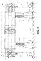
- a vibratory settling and compaction unit made according to the invention is located in the pocket 30 and is seen to include spaced base plates 32 which may be mounted to an extension of the surface 10 to one side of the end 26.
- the vibratory compaction unit includes a horizontally elongated clamping deck, generally designated 40.
- the clamping deck 40 includes a rectangular, central frame 42 closed by two metallic plates 44 and 46.
- the plate 44 defines a vertical face that faces the trailer receiving surface 10 and the universal container 14.
- a series of isolation springs 48 extend between pedestals 50 on the base plates 32 and the frame 42 of the clamping deck 10 so as to mount the latter above the base plates 32.
- an exciter mass is located and is generally designated 52.
- the same also is horizontally elongated, although somewhat shorter than the clamping deck 40 as can be seen in Fig. 2.
- the exciter mass 52 also includes a rectangular frame 54 which is sandwiched between plates 56 and 58.
- the plate 56 faces the plate 46 and a series of amplification springs 60 interconnect the exciter mass 52 and the clamping deck 40. Additional isolation springs 48 also support the exciter mass 52 above the base 32.
- the plate 58 mounts first and second vertically spaced motors 64 and 66.
- the motors 64, 66 are electric motors and rotate in opposite directions.
- each of the motors drives an eccentric weight 68 and because the motors 64 and 66 are vertical spaced, and because they are counter rotating, vibratory forces generated by the eccentric weights 68 in all directions but the horizontal will cancel out when the motors 64 and 66 rotate synchronously, something that occurs naturally in operation of the system. That is to say, when the motors 64 and 66 are in operation, vibratory force in the direction of an arrow 70 (Fig. 1) will be generated and will be purely in the horizontal direction.
- This vibratory force is, of course, imparted to the exciter mass 52 by reason of the motors 64 and 66 being mounted thereon.
- the amplification springs 60 will react thereto and transmit the vibration to the clamping deck 40 which will likewise vibrate in the horizontal direction.
- This horizontal vibration of the clamping deck 40 is imparted to the container 14 by means to be seen for the purpose of causing the contents therein to settle and be compacted during the loading process.
- two spaced clamps each generally designated 72, are located on opposite ends of the clamping deck 44. As each clamp 72 is identical to the other, only one will be described.
- each clamp 72 includes an eye bolt 74 having a threaded shaft 76 and an eye 78.
- the threaded shaft 76 is received in a nut 78 which is attached to a rotatable hand wheel 80.
- the nut 78 bears against a hardened steel washer 80 which in turn bears against a convex spherical washer 82 received in the concave face of a concave spherical washer 84.
- the latter bears against an adjusting plate 86, to be described in greater detail hereinafter, which in turn bears against a plate 88 which is backed by the plate 46 of the clamping deck.
- an S-shaped hook 90 is received in each of the eyes 78.
- the ends of the hooks 90 remote from the eyes 78 may be received in the openings 18 in the lifting pockets 16 on the universal container 14.
- the shaft 76 may be advanced toward the container 14 to loosen the clamping force or retracted from the container to tightly clamp the same to the clamping deck 44.
- the plate 44 mounts a pair of standoffs 92 which have contact blocks 94 for contacting the container 14.
- the contact blocks 94 may be of any suitable material.
- they may be made of steel or, in the alternative, so-called UHMW material, an ultra high molecular weight polymer.
- the contact blocks 94 are spaced a distance substantially equal to the spacing between the lifting pockets 16 on a universal container 14.
- each hook 90 is capable of vertical adjustment to the dotted line positions illustrated by reason of the presence of the spherical bearings 82 and 84. In some cases, it is desirable that an even greater range of vertical movement be permitted and to this end, a preferred embodiment of the invention provides a means whereby the vertical location of the hand wheels 80 can also be adjusted.
- the plate 88 is mounted to the plate 46 of the clamping deck 40 (see Fig. 3) and includes a vertically elongated slot 96 through which the shaft 76 of the eye bolt 74 extends.
- the plate 86 which abuts the plate 88, is provided with a vertically elongated slot 98 of the same length as the slot 96.
- a threaded stud 100 affixed to the plate 88 extends through the slot 98 to receive a clamping nut 102.
- a handle 104 is secured to the clamping nut 102.
- the plate 86 Remote from the slot 98, the plate 86 includes a circular opening 106 of slightly larger diameter than that of the shaft 76 and through which the shaft 76 extends.
- the plate 86 is mounted for vertical adjustment in the direction of an arrow 108 on the plate 88. Because the opening 106 receives the shaft 76 of the eye bolt 74, when the plate 86 is moved vertically, it takes the eye bolt with it to provide for vertical adjustment of the same.
- the plate 86 may be held against the plate 88 and any position of adjustment simply by rotating the handle 104 in the direction of an arrow 110 to tighten the clamping nut 102 against the plate 86. To loosen the clamping nut 102, the handle may be moved in a direction shown by an arrow 112.
- the vertical position of the eye bolt 74 can be changed by tilting the same through use of the spherical bearings 82 and 84 or by elevating or lowering the plate 86 on the plate 88 or both.
- elongated guide rails 114 (Figs. 1, 2 and 3) are provided.
- the guide rails 114 are spaced so as to be engageable with the side walls of the tires 12 and cause the trailer to be moved to a position whereat the lifting pockets 16 of the container 14 engage the contact blocks 94 to allow the hooks 90 to be inserted in the openings 18 of the lifting pockets 16.
- the trailer In use, the trailer is moved into the desired position and latched to the clamping deck 40 by engaging the hooks 90 in the openings 18 in the lifting pockets and appropriately operating the hand wheels 80. This will firmly clamp the container 14 to the clamping deck 40.
- the equipment employed to fill the container 14 may then be put in operation and the filling procedure initiated.
- the motors 64 and 66 may be energized to cause the vibratory settling and compaction unit to begin operation. Vibration will be imparted to the container 14 as the filling operation continues, with the result that the contents of the container 14 will be settled almost as soon as they are introduced thereinto. The operation continues until the container 14 is filled, at which time the container may be sealed, the motors 64 and 66 deenergized, and the hooks 90 released. At this point, the vast majority of the settling of the material that would occur in shipping under normal circumstances will have already occurred allowing for a substantial increase in the quantity of material that can be shipped in a single one of the containers 14. As a consequence, users of the system realize substantial savings in shipping costs.
- the vibration imparted to the container 14 is at right angles to the rotational axes of the wheels 12. Consequently, the vibration acts on the trailer axles or wheel spindles in the same direction as the normal rolling motion of the trailer when in transit. Thus, no motion that would stress the wheel bearings more than that incurred in normal usage is imparted thereto.
- the use of the clamps 72 and contact blocks 94 avoids hammering of the container so that damage is eliminated. And importantly, this feature of the invention enhances settling action. If a hammering action was used, only one stroke per revolution the motors 64, 66 would be applied to the container 14, namely the stroke applied as the clamping deck or hammer moves toward the container.
Landscapes
- Engineering & Computer Science (AREA)
- Mechanical Engineering (AREA)
- Basic Packing Technique (AREA)
- Jigging Conveyors (AREA)
- Loading Or Unloading Of Vehicles (AREA)
Claims (13)
- Vibrationsverdichtungseinheit zum Verdichten eines teilchenförmigen Materials in einem Transportcontainer (14) des Typs, der an zuvor bestimmten Positionen beanstandete Hubtaschen (16) darauf besitzt und für den Transport auf einem Fahrzeug mit Rädern konzipiert ist, wobei die Einheit Vibrationsübertragungsmittel (64, 66) auf einer Erregermasse (52) einschließt, die in die Containerhubtaschen (16) eingreifen können, gekennzeichnet durch:wobei die Erregermasse von dem Klemmdeck auf der der vertikalen Fläche gegenüber liegenden Seite beabstandet, ihm jedoch benachbart ist.ein Klemmdeck (40) mit einer im Allgemeinen vertikalen Fläche (44);beabstandete, sich von der Fläche erstreckende Kontaktblöcke (94) auf dem Deck, wobei der Abstand zwischen den Kontaktblöcken im Wesentlichen gleich dem Abstand zwischen den Hubtaschen ist;Klemmmittel (72) auf dem Klemmdeck für den Eingriff in Hubtaschen (16) auf dem Container, die so eingestellt sind, dass sie den Container fest gegen die Kontaktblöcke klemmen; undVerstärkungsfedern (60), die das Klemmdeck (40) und die Erregermasse verbinden;
- Vibrationsverdichtungseinheit nach Anspruch 1, die weiterhin ein elastisches Isoliermittel (48) umfasst, das das Klemmdeck und die Erregermasse an einer Grundfläche (32, 50) befestigt.
- Vibrationsverdichtungseinheit nach Anspruch 1 oder 2, bei der die Klemmmittel (72) von Hubtaschen (16) aufnehmbare Haken (90) sowie Mittel zum Bewegen der Haken in Richtung des Klemmdecks (40) einschließen.
- Vibrationsverdichtungseinheit nach Anspruch 2, bei der die Bewegungsmittel manuell betätigt werden können.
- Vibrationsverdichtungseinheit nach Anspruch 3, bei der die Bewegungsmittel ein Handrad (80) einschließen.
- Vibrationsverdichtungseinheit nach Anspruch 1, die weiterhin Mittel zur Befestigung der Klemmmittel (72) auf dem Klemmdeck (40) zur vertikalen Justierung dort einschließt.
- Verladerampe mit der Vibrationsverdichtungseinheit nach Anspruch 1, die weiterhin eine Anhängeraufnahmefläche (10) besitzt; und
eine erhöhte Verladefläche (24) an einem Ende (26) der Anhängeraufnahmefläche (10);
wobei sich die Vibrationsverdichtungseinheit an dem einen Ende (26) direkt unter der Verladefläche (24) und über der Aufnahmefläche (10) befindet und mit der Grundfläche (32, 50) daran befestigt ist, wobei die Fläche (44) der Aufnahmefläche (10) im Allgemeinen gegenüber liegt. - Verladerampe nach Anspruch 7, die weiterhin beabstandete, parallele Führungsschienen (114) entlang der Aufnahmefläche für den Eingriff und die Führung der Räder (12) eines Anhängers in Richtung des einen Endes einschließt.
- Verladerampe nach Anspruch 8, bei der das Vibrationsübertragungsmittel Vibrationen in im Wesentlichen horizontaler Richtung überträgt, wobei die im Wesentlichen horizontale Richtung im Wesentlichen parallel zu den Führungsschienen (14) ist.
- Vibrationsverdichtungseinheit nach Anspruch 1, bei der die Klemmmittel (72) ein Paar beabstandete Klammern (72) umfassen, die an entgegen gesetzten Enden des Klemmdecks (40) befestigt sind.
- Vibrationsverdichtungseinheit nach Anspruch 10, bei der die Klemmmittel (72) manuell betätigt werden können.
- Vibrationsverdichtungseinheit nach Anspruch 11, bei der die Klammern (72) jeweils einen Gewindeschaft (76), ein auf den Schaft (76) gewindetes Handrad (80) und einen mit dem Schaft (76) verbundenen Haken (90) umfassen, der von dem Handrad (80) entfernt und für die Aufnahme in die Hubtasche (16) eines Transportcontainers (14) konzipiert ist.
- Vibrationsverdichtungseinheit nach Anspruch 12, die weiterhin Mittel zur Befestigung der Klammem (72) zur vertikalen Justierung auf dem Klemmdeck (40) einschließt.
Applications Claiming Priority (2)
| Application Number | Priority Date | Filing Date | Title |
|---|---|---|---|
| US08/627,702 US5669711A (en) | 1996-03-29 | 1996-03-29 | Vibratory settling or compaction unit |
| US627702 | 1996-03-29 |
Publications (3)
| Publication Number | Publication Date |
|---|---|
| EP0798244A2 EP0798244A2 (de) | 1997-10-01 |
| EP0798244A3 EP0798244A3 (de) | 1998-07-22 |
| EP0798244B1 true EP0798244B1 (de) | 2003-12-17 |
Family
ID=24515764
Family Applications (1)
| Application Number | Title | Priority Date | Filing Date |
|---|---|---|---|
| EP97301080A Expired - Lifetime EP0798244B1 (de) | 1996-03-29 | 1997-02-18 | Vibrations-Absetz-oder Verdichtungseinheit |
Country Status (5)
| Country | Link |
|---|---|
| US (1) | US5669711A (de) |
| EP (1) | EP0798244B1 (de) |
| JP (1) | JP3739520B2 (de) |
| CA (1) | CA2197977C (de) |
| DE (1) | DE69726784T2 (de) |
Families Citing this family (9)
| Publication number | Priority date | Publication date | Assignee | Title |
|---|---|---|---|---|
| US6782995B2 (en) | 2002-06-06 | 2004-08-31 | Precision Components & Assemblies, Inc. | Two-way vibratory conveyor and stabilizer rocker arm therefor |
| US7497324B2 (en) | 2005-01-20 | 2009-03-03 | Conveyor Dynamics Corporation | Conveyor system for two or more troughs |
| US20070065261A1 (en) * | 2005-09-06 | 2007-03-22 | Chambers Arthur N | Apparatus and system for densifying and transporting bulk materials, and related methods |
| US7553064B2 (en) * | 2007-02-09 | 2009-06-30 | Johnson Matthew J | Agitating and conveying machine for shaking a container |
| CN106540617B (zh) * | 2016-10-25 | 2018-06-22 | 胡生红 | 一种农产业液体肥料用齿轮齿条式混合装置 |
| AU2018100085A4 (en) | 2017-02-24 | 2018-03-01 | General Kinematics Corporation | Spring assembly with a protected attachment site |
| US10384877B2 (en) | 2017-12-08 | 2019-08-20 | General Kinematics Corporation | Spring assembly with transverse attachment site |
| CN109850418B (zh) * | 2018-11-26 | 2020-08-25 | 温州飞龙聚氨酯设备工程有限公司 | 一种电磁高效激振混合装置 |
| CN115947148B (zh) * | 2022-12-30 | 2025-11-14 | 湖北航鹏化学动力科技有限责任公司 | 一种药剂振动装置 |
Family Cites Families (16)
| Publication number | Priority date | Publication date | Assignee | Title |
|---|---|---|---|---|
| US2013235A (en) * | 1932-01-15 | 1935-09-03 | Atlas Press Company | Vibrating detector for automobiles |
| US2431872A (en) * | 1944-05-16 | 1947-12-02 | Kavula Alex | Mold vibrator |
| US2489869A (en) * | 1948-03-01 | 1949-11-29 | Western Electric Co | Loading platform |
| US2648447A (en) * | 1949-02-24 | 1953-08-11 | American Car & Foundry Co | Vehicle unloader |
| US2648448A (en) * | 1949-04-01 | 1953-08-11 | American Car & Foundry Co | Vehicle unloader car |
| US2706566A (en) * | 1951-12-27 | 1955-04-19 | Vibro Plus Corp | Vibrating attachment for hopper cars and the like |
| US2850185A (en) * | 1956-11-21 | 1958-09-02 | Link Belt Co | Receptacle unloader |
| US3047169A (en) * | 1959-02-12 | 1962-07-31 | Vibrator Mfg Company | Railroad car vibrator |
| DE1170873B (de) * | 1959-02-12 | 1964-05-21 | Hewitt Robins Internat S A | Ruettelvorrichtung zum Entladen von Schuettgut aus Wagen |
| AT262012B (de) * | 1965-03-22 | 1968-05-27 | Venanzetti Vibrazioni S A | Vibrationseinrichtung |
| US4017060A (en) * | 1971-12-09 | 1977-04-12 | International Combustion Australia Limited | Tuned vibratory feeders |
| FR2367542A1 (fr) * | 1976-10-12 | 1978-05-12 | Brigolle Roger | Generateur de vibrations, du |
| US4224006A (en) * | 1978-09-28 | 1980-09-23 | Vibranetics, Inc. | Hopper car discharge apparatus |
| US4307989A (en) * | 1979-10-15 | 1981-12-29 | Kinergy Corporation | Vibrating densifier for car lading |
| US4600046A (en) * | 1984-01-04 | 1986-07-15 | Outboard Marine Corporation | Molding apparatus and process including sand compaction system |
| US5139359A (en) * | 1989-05-30 | 1992-08-18 | Amoco Corporation | Vibrator-steamship truck container clamp assembly |
-
1996
- 1996-03-29 US US08/627,702 patent/US5669711A/en not_active Expired - Lifetime
-
1997
- 1997-02-18 DE DE69726784T patent/DE69726784T2/de not_active Expired - Fee Related
- 1997-02-18 EP EP97301080A patent/EP0798244B1/de not_active Expired - Lifetime
- 1997-02-19 CA CA002197977A patent/CA2197977C/en not_active Expired - Fee Related
- 1997-03-19 JP JP08470797A patent/JP3739520B2/ja not_active Expired - Fee Related
Also Published As
| Publication number | Publication date |
|---|---|
| DE69726784D1 (de) | 2004-01-29 |
| DE69726784T2 (de) | 2004-06-17 |
| EP0798244A2 (de) | 1997-10-01 |
| JPH09267802A (ja) | 1997-10-14 |
| US5669711A (en) | 1997-09-23 |
| CA2197977C (en) | 2006-09-19 |
| EP0798244A3 (de) | 1998-07-22 |
| JP3739520B2 (ja) | 2006-01-25 |
| CA2197977A1 (en) | 1997-09-30 |
Similar Documents
| Publication | Publication Date | Title |
|---|---|---|
| US5669711A (en) | Vibratory settling or compaction unit | |
| US4685174A (en) | Shock absorbing caster wheel suspension with frictional vertical oscillation dampening | |
| CN216155310U (zh) | 吊具装置 | |
| EP0699167B1 (de) | Kippvorrichtung für fahrzeuge mit pulsierender plattform und bewegbarem scharnier | |
| CN211001485U (zh) | 一种防止货物倾倒的物流运输车 | |
| CN214610477U (zh) | 集装箱振动翻转平台 | |
| US2504789A (en) | Hopper car discharge apparatus | |
| US3648862A (en) | Goods transfer device for motor wagon and trailer van based on vibratory principle | |
| CN210821965U (zh) | 一种翻斗车液压翻斗 | |
| US4039128A (en) | Vibrator bracket assembly for hoppers and railway cars | |
| CN219277567U (zh) | 一种自卸式送料车 | |
| CN2433236Y (zh) | 电动自卸翻斗车 | |
| CN214030985U (zh) | 集装箱振动翻转平台 | |
| US5080390A (en) | Vehicle with plastic suspension | |
| CN211895205U (zh) | 一种集装箱极速装车用角度可调整装车对位机构 | |
| CN210162493U (zh) | 一种混凝土防腐抗裂增强剂用储罐的运输防护结构 | |
| CN221367055U (zh) | 一种用于液晶屏的防撞搬运装置 | |
| US20200361702A1 (en) | Vibratory cargo handling system for shipping containers | |
| CA1173625A (en) | Vertical face shake out for foundry molds | |
| CN220131378U (zh) | 一种集装箱翻转吊具振动装置 | |
| CN220220846U (zh) | 一种酒桶搬运车及其酒桶翻转抱夹装置 | |
| CN221273081U (zh) | 物流仓储转运装置 | |
| CN220053889U (zh) | 具有防碰撞结构的推料车 | |
| US2648447A (en) | Vehicle unloader | |
| CN214877991U (zh) | 一种可调节的货物输送设备 |
Legal Events
| Date | Code | Title | Description |
|---|---|---|---|
| PUAI | Public reference made under article 153(3) epc to a published international application that has entered the european phase |
Free format text: ORIGINAL CODE: 0009012 |
|
| AK | Designated contracting states |
Kind code of ref document: A2 Designated state(s): DE FR GB IT |
|
| PUAL | Search report despatched |
Free format text: ORIGINAL CODE: 0009013 |
|
| AK | Designated contracting states |
Kind code of ref document: A3 Designated state(s): DE FR GB IT |
|
| RHK1 | Main classification (correction) |
Ipc: B65D 88/66 |
|
| 17P | Request for examination filed |
Effective date: 19981230 |
|
| 17Q | First examination report despatched |
Effective date: 20020801 |
|
| GRAH | Despatch of communication of intention to grant a patent |
Free format text: ORIGINAL CODE: EPIDOS IGRA |
|
| GRAH | Despatch of communication of intention to grant a patent |
Free format text: ORIGINAL CODE: EPIDOS IGRA |
|
| GRAA | (expected) grant |
Free format text: ORIGINAL CODE: 0009210 |
|
| AK | Designated contracting states |
Kind code of ref document: B1 Designated state(s): DE FR GB IT |
|
| REG | Reference to a national code |
Ref country code: GB Ref legal event code: FG4D |
|
| REF | Corresponds to: |
Ref document number: 69726784 Country of ref document: DE Date of ref document: 20040129 Kind code of ref document: P |
|
| ET | Fr: translation filed | ||
| PLBE | No opposition filed within time limit |
Free format text: ORIGINAL CODE: 0009261 |
|
| STAA | Information on the status of an ep patent application or granted ep patent |
Free format text: STATUS: NO OPPOSITION FILED WITHIN TIME LIMIT |
|
| 26N | No opposition filed |
Effective date: 20040920 |
|
| PGFP | Annual fee paid to national office [announced via postgrant information from national office to epo] |
Ref country code: DE Payment date: 20090219 Year of fee payment: 13 |
|
| PGFP | Annual fee paid to national office [announced via postgrant information from national office to epo] |
Ref country code: GB Payment date: 20090219 Year of fee payment: 13 |
|
| PGFP | Annual fee paid to national office [announced via postgrant information from national office to epo] |
Ref country code: IT Payment date: 20090221 Year of fee payment: 13 |
|
| PGFP | Annual fee paid to national office [announced via postgrant information from national office to epo] |
Ref country code: FR Payment date: 20090220 Year of fee payment: 13 |
|
| GBPC | Gb: european patent ceased through non-payment of renewal fee |
Effective date: 20100218 |
|
| REG | Reference to a national code |
Ref country code: FR Ref legal event code: ST Effective date: 20101029 |
|
| PG25 | Lapsed in a contracting state [announced via postgrant information from national office to epo] |
Ref country code: FR Free format text: LAPSE BECAUSE OF NON-PAYMENT OF DUE FEES Effective date: 20100301 |
|
| PG25 | Lapsed in a contracting state [announced via postgrant information from national office to epo] |
Ref country code: DE Free format text: LAPSE BECAUSE OF NON-PAYMENT OF DUE FEES Effective date: 20100901 |
|
| PG25 | Lapsed in a contracting state [announced via postgrant information from national office to epo] |
Ref country code: GB Free format text: LAPSE BECAUSE OF NON-PAYMENT OF DUE FEES Effective date: 20100218 Ref country code: IT Free format text: LAPSE BECAUSE OF NON-PAYMENT OF DUE FEES Effective date: 20100218 |