EP0699167B1 - Kippvorrichtung für fahrzeuge mit pulsierender plattform und bewegbarem scharnier - Google Patents
Kippvorrichtung für fahrzeuge mit pulsierender plattform und bewegbarem scharnier Download PDFInfo
- Publication number
- EP0699167B1 EP0699167B1 EP94917936A EP94917936A EP0699167B1 EP 0699167 B1 EP0699167 B1 EP 0699167B1 EP 94917936 A EP94917936 A EP 94917936A EP 94917936 A EP94917936 A EP 94917936A EP 0699167 B1 EP0699167 B1 EP 0699167B1
- Authority
- EP
- European Patent Office
- Prior art keywords
- platform
- movement
- truck
- pulsation
- dumping apparatus
- Prior art date
- Legal status (The legal status is an assumption and is not a legal conclusion. Google has not performed a legal analysis and makes no representation as to the accuracy of the status listed.)
- Expired - Lifetime
Links
- 230000010349 pulsation Effects 0.000 claims abstract description 28
- 230000001133 acceleration Effects 0.000 claims description 4
- 239000000463 material Substances 0.000 abstract description 15
- 238000005096 rolling process Methods 0.000 description 4
- 230000005484 gravity Effects 0.000 description 2
- 208000027418 Wounds and injury Diseases 0.000 description 1
- 240000008042 Zea mays Species 0.000 description 1
- 235000005824 Zea mays ssp. parviglumis Nutrition 0.000 description 1
- 235000002017 Zea mays subsp mays Nutrition 0.000 description 1
- 239000013590 bulk material Substances 0.000 description 1
- 238000005056 compaction Methods 0.000 description 1
- 235000005822 corn Nutrition 0.000 description 1
- 230000006378 damage Effects 0.000 description 1
- 230000009969 flowable effect Effects 0.000 description 1
- 208000014674 injury Diseases 0.000 description 1
- 239000000725 suspension Substances 0.000 description 1
- 238000005303 weighing Methods 0.000 description 1
- 239000002023 wood Substances 0.000 description 1
Images




Classifications
-
- B—PERFORMING OPERATIONS; TRANSPORTING
- B65—CONVEYING; PACKING; STORING; HANDLING THIN OR FILAMENTARY MATERIAL
- B65G—TRANSPORT OR STORAGE DEVICES, e.g. CONVEYORS FOR LOADING OR TIPPING, SHOP CONVEYOR SYSTEMS OR PNEUMATIC TUBE CONVEYORS
- B65G67/00—Loading or unloading vehicles
- B65G67/02—Loading or unloading land vehicles
- B65G67/24—Unloading land vehicles
- B65G67/32—Unloading land vehicles using fixed tipping installations
- B65G67/34—Apparatus for tipping wagons or mine cars
- B65G67/36—Apparatus for tipping wagons or mine cars endwise
- B65G67/40—Apparatus for tipping wagons or mine cars endwise toward one end only
Definitions
- the vehicle dumping apparatus of my U.S.patent 3,118,550, January 21, 1964 has been very successful in the grain industry. It involves a grain truck on a platform elevated at one end by a fixed vertical cylinder which has a roller on its upper end in engagement with a curved track on the bottom side of the platform.
- the curved track is positioned such that the substantial downward pressure from the platform and truck is along the vertical axis of the cylinder thus minimizing horizontal forces on the cylinder which would tend to flex or bend it.
- German patent DE-A-477,305 shows a container 2 and platform 1 being supported on cables.
- a vibration means includes an electric motor for about whose shaft the rotating masses are distributed unevenly to cause a vibration.
- the entire dumper or platform 1 and container or car 2 are shaken. There is no teaching of moving the platform in only a horizontal direction.
- the platform and container are both vibrated in all directions rather than being moved only in a horizontal direction.
- Fig. 2 relating to an embodiment corresponding to the one according to the first part of claim 1, the platform is fixed at a pivot point 11 which absolutely prevents horizontal movement of the platform.
- This invention contemplates breaking the material in the truck box loose through the combined influence of an elevated platform and truck at approximately 30° and horizontal pulsations being applied to the platform and in turn the truck to take advantage of the inertial and gravitational forces at work on the material tending to slide it to the rear end of the truck and then into a receiving pit.
- a pair of hydraulic cylinders, one on each side, is connected through a rolling hinge to the platform for reciprocating it within the limits of a stationary stop.
- a preferred cycle of operation is utilized wherein the pulsation cylinders move the platform and truck rearwardly with increasing velocity for a distance of approximately 7.6 cm (3 inches) at which point the movement is quickly stopped hydraulically by the pulsation cylinders.
- the material continues to move rearwardly and downwardly as a result of inertia and gravity in a stair step fashion as the cycle is repeated.
- a pause between cycles is introduced to avoid any harmonic movements.
- the angle of elevation and frequency of pulsation will depend on the material in the truck and how flowable it is.
- the distance the platform will travel will vary up to approximately 15.2 cm (6 inches) with the platform elevated up to approximately 35°.
- the maximum load on the hinge connections between the pulsation cylinders and the platform will be approximately 18144 kg (40,000 pounds).
- the cylinder pressure during braking is not expected to exceed 141 kg/cm 2 (2,000 PSI) and this will give up to 18144 kg (40,000 pounds) of force at each hinge.
- a rearward force of 10,000 pounds through a distance of 7.6 cm (3 inches) will produce a rearward velocity of 3.2 kilometers/hour (2 miles per hour) on a truck weighing 36287 kg (80,000 pounds).
- Braking with a force of 18144 kg (40,000 pounds) at each hinge stops the movement in 0.12 seconds in a distance of 1.0 cm (0.4 inches). For that short period of time, it is equivalent to having the load tilted almost vertically.
- Figure 1 is a side elevation view of a truck on a platform shown in raised and lowered positions.
- Figure 2 is a top plan view thereof.
- Figure 3 is a perspective view of the hinge connection between the pulsation cylinder and the rear end of the platform.
- Figure 4 is a side elevational view thereof taken along line 4 - 4 in Figure 1.
- Figure 5 is an exploded perspective view of the connection between the pulsation cylinder and the rear end of the platform.
- Figure 6 is a cross sectional view of the hinge connection between the pulsation cylinder and the rear end of the platform taken along line 6 - 6 in Figure 4.
- Figure 7 is a top plan view thereof taken along line 7 - 7 in Figure 4.
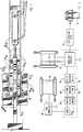
- Figure 8 is a hydraulic schematic of the hydraulic circuitry for operation of the system.
- Figure 9 is a fragmentary side elevation view of the platform during raising with the platform in the forward position.
- Figure 10 is a view similar to Figure 9 but showing the platform in the forward position in preparation to move rearward where as it slowly accelerates and then quickly decelerates resulting in the material being unloaded to momentarily break free from the truck and move rearward of the truck.
- Figure 11 is a graph of one complete pulsation cycle illustrating changes in velocity and acceleration.
- Figure 12 is a graph illustrating the hinge travel throughout the pulsation cycle.
- the vehicle platform of this invention is referred to generally in Figure 1 by the reference numeral 10 and is seen having a truck 12 with a trailer 14 positioned to unload bulk material into a receiving pit 16 through a slatted floor 18.
- the forward end of the platform 10 is supported by a stationary support 20 and a fixed vertical cylinder 22 engages the platform approximately midway for raising it to the dash line position shown in Figure 1.
- the details of the vertical cylinder 22 and its engagement with a curved track assembly 24 as seen in Figures 9 and 10 are more fully described in my patent 3,118,550.
- the cylinder 22 includes a roller 26 at its upper end which engages the curved tracks 24 such that the substantial forces on the cylinder are along its vertical axis thus minimizing horizontal forces which would tend to flex or bend the cylinder.
- the rearward end of the platform is connected to a pair of laterally spaced apart pulsation cylinders 30 by a rolling hinge assembly 31 as seen in Figures 1 and 5.
- the pulsation cylinders 30 are connected at one end to a pair of spaced apart plates 32 which in turn are connected to an upstanding hinge base 34 anchored to a foundation 36 by bolts 38.
- the forward end of the cylinder 30 is connected through a pin 40 to a clevis 42 having side plates 44.
- Pin 48 pivotally connects an ear member 46 extending rearwardly from the platform 10 to side plates of 44. Pin 48 extends past side plates 44 to receive rollers 50.
- the rollers 50 travel in slots 52 in a pair of spaced apart fixed plates 54. Slots 52 define travel limits.
- the clevis 42 with side plates 44 is guided horizontally by vertically spaced apart guide plates 55 on plates 32 and by the pin 48 with its rollers 50 traveling in the horizontal slot 52.
- cover plates 56 are secured by bolts 58 to plates 32.
- the rolling hinge 31 is in the forward position until the desired tilt angle is reached at which time the pulsation cylinders 30 retract, rolling the platform 10 rearwardly on rollers 26 and 50, as illustrated in Figure 10, from the solid line position to the dashed line position.
- the pulsation cylinders 30 accelerate the platform 10 and truck rearwardly and then decelerate it abrupty stopping the platform and truck.
- the material on the bottom of the truck bed, as represented by the arrows 60 in Figure 10 will tend to stair step down the incline toward the pit 16. Depending on the material in the truck, it may actually move off the floor into temporary suspension while gravity combined with its momentum and inertia moves it downwardly and rearwardly.
- the pulsation cylinders 30 are operated by a motor 62 connected to a pump 64 in turn connected to a horizontal pulse module (HPM) manifold 66.
- the motor 62 also drives a pump 68 through a relief valve 70 connected to a manifold 72 in turn connected to a deceleration valve 74 and the vertical cylinder 22.
- the manifold 72 also supplies power to a pair of backstop cylinders 76 connected to the wheel backstops 78 as seen in Figure 1.
- a second motor 80 connected to a pump 82 through a relief valve 84 may be used as a backup or to increase the speed of operation of the backstop cylinder 76 and thee vertical cylinder 22.
- the backstop 78 may be pivoted into the floor of the platform such that the truck may be driven over it.
Landscapes
- Engineering & Computer Science (AREA)
- Aviation & Aerospace Engineering (AREA)
- Mechanical Engineering (AREA)
- Loading Or Unloading Of Vehicles (AREA)
- Auxiliary Methods And Devices For Loading And Unloading (AREA)
- Hinge Accessories (AREA)
- Fittings On The Vehicle Exterior For Carrying Loads, And Devices For Holding Or Mounting Articles (AREA)
- Body Structure For Vehicles (AREA)
- Soil Working Implements (AREA)
- Fluid-Pressure Circuits (AREA)
- Vehicle Step Arrangements And Article Storage (AREA)
Claims (7)
- Kippvorrichtung für Fahrzeuge mit einer ein vorderes Ende und ein hinteres Ende aufweisenden Plattform, einem Scharniermittel (31), das das hintere Plattformende mit einem Träger (36) drehbar verbindet, einem Kraftmittel (22), das an der Plattform zur drehbaren Anhebung und Absenkung der Plattform (10) angreift, und mit einem mit der Plattform (10) verbundenen Pulsationsmittel (30) zur Hin- und Herbewegung der Plattform (10), wenn diese sich in der angehobenen Position befindet, dadurch gekennzeichnet, daß das Pulsationsmittel (30) derart mit der Plattform (10) verbunden ist, daß es die Plattform (10) durch einen Zyklus mit nur horizontaler Bewegung bewegt, die die Bewegung nach hinten, die plötzliche Änderung der Bewegungsgeschwindigkeit und eine Rückkehr nach vorne einschließt.
- Kippvorrichtung für Fahrzeuge nach Anspruch 1, dadurch gekennzeichnet, daß das Pulsationsmittel einen Antriebszylinder aufweist, der mit dem hinteren Plattformende verbunden ist und die Plattform hin- und herbewegt, wenn diese sich in angehobener Position befindet.
- Kippvorrichtung für Fahrzeuge nach Anspruch 2, dadurch gekennzeichnet, daß die Plattform (10) einen Arbeitshubweg (M) aufweist und daß in diesem Arbeitshubweg (M) ein Stoppmittel (30; 34) vorgesehen ist, das die Plattformbewegung nach hinten plötzlich begrenzt.
- Kippvorrichtung für Fahrzeuge nach Anspruch 3, dadurch gekennzeichnet, daß die Plattform (10) einen Hubweg durchläuft, daß das Stoppmittel (30; 34) den Antriebszylinder (30) und ein stationäres, einen Schlitz (52) bestimmter Länge aufweisendes Glied (54) umfaßt und daß das Scharniermittel (31) einen Drehbolzen (48) aufweist, der den Antriebszylinder (30) mit dem hinteren Plattformende verbindet und in dem den Schlitz aufweisenden Glied (54) aufgenommen wird, wobei der Hubweg der Plattform (10) auf die Länge des Schlitzes (52) begrenzt wird.
- Kippvorrichtung für Fahrzeuge nach Anspruch 1, dadurch gekennzeichnet, daß das Pulsationsmittel (30) die Plattform (10) durch einen Bewegungszyklus bewegt, der die Beschleunigung nach hinten, die plötzliche Verzögerung und eine Rückkehr nach vorne umfaßt, wobei die Zeit der Bewegung nach hinten geringer als die Zeit der Bewegung nach vorne ist.
- Kippvorrichtung für Fahrzeuge nach Anspruch 5, dadurch gekennzeichnet, daß das Pulsationsmittel (30) eine Pause veranlaßt, die nach der plötzlichen Verzögerung und vor der Wiederholung des Zyklus auftritt.
- Verfahren zum Abladen eines Behälters auf einer um einen gewissen Winkel angehobenen Plattform (10), die mit einem Pulsationsmittel (30) verbunden ist, dadurch gekennzeichnet, daß das Pulsationsmittel (30) derart betrieben wird, daß die Plattform (10) durch viele Zyklen von nur horizontaler Bewegung bewegt wird, die die Bewegung nach hinten, eine folgend plötzliche Verzögerung und eine Rückkehr nach vorne einschließt, wobei die Zeit der Bewegung nach hinten kleiner als die Zeit der Bewegung nach vorne ist.
Applications Claiming Priority (3)
| Application Number | Priority Date | Filing Date | Title |
|---|---|---|---|
| US08/069,164 US5360308A (en) | 1993-05-28 | 1993-05-28 | Vehicle dumping apparatus with pulsating platform and movable hinge |
| US69164 | 1993-05-28 | ||
| PCT/US1994/005109 WO1994027899A1 (en) | 1993-05-28 | 1994-05-09 | Vehicule dumping apparatus with pulsating platform and movable hinge |
Publications (2)
| Publication Number | Publication Date |
|---|---|
| EP0699167A1 EP0699167A1 (de) | 1996-03-06 |
| EP0699167B1 true EP0699167B1 (de) | 1997-07-30 |
Family
ID=22087158
Family Applications (1)
| Application Number | Title | Priority Date | Filing Date |
|---|---|---|---|
| EP94917936A Expired - Lifetime EP0699167B1 (de) | 1993-05-28 | 1994-05-09 | Kippvorrichtung für fahrzeuge mit pulsierender plattform und bewegbarem scharnier |
Country Status (13)
| Country | Link |
|---|---|
| US (1) | US5360308A (de) |
| EP (1) | EP0699167B1 (de) |
| JP (1) | JPH09500349A (de) |
| CN (1) | CN1069087C (de) |
| AT (1) | ATE156091T1 (de) |
| AU (1) | AU676742B2 (de) |
| BR (1) | BR9406698A (de) |
| CA (1) | CA2162672C (de) |
| DE (1) | DE69404649T2 (de) |
| DK (1) | DK0699167T3 (de) |
| ES (1) | ES2107231T3 (de) |
| GR (1) | GR3025230T3 (de) |
| WO (1) | WO1994027899A1 (de) |
Families Citing this family (15)
| Publication number | Priority date | Publication date | Assignee | Title |
|---|---|---|---|---|
| US5739477A (en) * | 1995-01-12 | 1998-04-14 | Queen; C. Ray | Portable apparatus for monitoring the weight of a vehicle |
| US7114909B2 (en) * | 2002-11-25 | 2006-10-03 | Ty-Crop Manufacturing, Ltd. | Trailer-tilting, load-discharge apparatus and method |
| US7658266B1 (en) | 2005-07-25 | 2010-02-09 | Norfolk Southern Corporation | Truck bed staircase device |
| US20070065260A1 (en) * | 2005-08-23 | 2007-03-22 | Chapman Don K | Trailer tipper backstop and safety hoop |
| US20090317218A1 (en) * | 2005-08-23 | 2009-12-24 | Phelps Industries, Inc. | Container tilter |
| US8827622B2 (en) | 2010-05-03 | 2014-09-09 | Air-Cure Incorporated | Truck dumper dust control |
| WO2012172569A1 (en) * | 2011-06-15 | 2012-12-20 | Chhabra Mahesh Kumar | Apparatus for dumping agricultural produce loaded on a vehicle |
| CN103086171A (zh) * | 2011-10-28 | 2013-05-08 | 酒泉奥凯种子机械股份有限公司 | 自动卸料装置 |
| CN103253524A (zh) * | 2013-05-13 | 2013-08-21 | 上海凯睿达机电设备有限公司 | 自动卸料系统 |
| CN205772114U (zh) * | 2015-12-09 | 2016-12-07 | 广东科利亚现代农业装备有限公司 | 一种甘蔗卸车清洗平台 |
| CN105905632A (zh) * | 2015-12-09 | 2016-08-31 | 广东科利亚现代农业装备有限公司 | 一种汽车翻转平台的护栏装置 |
| DE102019122052B4 (de) | 2019-08-16 | 2021-03-04 | Fraunhofer-Gesellschaft zur Förderung der angewandten Forschung e.V. | Fahrzeug zum Transportieren von Ladegut |
| DE102019122055B4 (de) | 2019-08-16 | 2021-08-26 | Fraunhofer-Gesellschaft zur Förderung der angewandten Forschung e.V. | Verfahren zur Übergabe von Ladegut von einer Ladegutaufnahme eines Fahrzeuges sowie Fahrzeug zur Durchführung des Verfahrens |
| US12157647B2 (en) * | 2020-08-04 | 2024-12-03 | Intelligrated Headquarters, Llc | Unloading system and method of using the same |
| CN112110223B (zh) * | 2020-09-04 | 2022-01-14 | 安徽省凯杰机械制造有限公司 | 智能化集装箱散粮后卸平台系统 |
Family Cites Families (18)
| Publication number | Priority date | Publication date | Assignee | Title |
|---|---|---|---|---|
| US1126392A (en) * | 1913-03-15 | 1915-01-26 | Co Bartlett & Snow Co | Car transferring and dumping mechanism. |
| US1530337A (en) * | 1922-03-20 | 1925-03-17 | Algot A Wickland | Cupola-charging machine |
| DE483870C (de) * | 1926-10-10 | 1929-10-09 | Demag Akt Ges | Mit einem Kipper verbundene Erschuetterungsvorrichtung |
| DE477305C (de) * | 1927-10-16 | 1929-06-05 | Demag Akt Ges | Vorrichtung zur Entleerung von Wagen auf Kippern |
| US1968624A (en) * | 1931-06-08 | 1934-07-31 | Globe Machinery & Supply Compa | Grain dump |
| US2282621A (en) * | 1939-10-02 | 1942-05-12 | Globe Hoist Co | Vehicle dumping apparatus |
| US2284226A (en) * | 1940-02-23 | 1942-05-26 | Richard W Oglesby | Wagon dump device |
| US2523212A (en) * | 1948-03-12 | 1950-09-19 | Hight Alec Turner | Vehicle body vibrator |
| SU117422A1 (ru) * | 1954-02-19 | 1957-11-30 | А.В. Будный | Устройство дл выгрузки свеклы из автомобилей и укладки её в бурты |
| US2774493A (en) * | 1954-10-07 | 1956-12-18 | August P Winter | Method for unloading vehicles |
| US2793767A (en) * | 1955-05-16 | 1957-05-28 | Smith | Truck hoist |
| GB898864A (en) * | 1957-09-03 | 1962-06-14 | W G Allen And Sons Tipton Ltd | Improvements relating to tipplers for vehicles |
| US2953262A (en) * | 1958-02-21 | 1960-09-20 | Newaygo Engineering Company | Power mold dump |
| US3118550A (en) * | 1960-10-10 | 1964-01-21 | Straight Engineering Company | Vehicle dumping apparatus |
| US3400770A (en) * | 1966-12-19 | 1968-09-10 | Carl G. Matson | Vibrator apparatus |
| US3574332A (en) * | 1969-06-09 | 1971-04-13 | Clifford C Wetzel | Trailer lifting and dumping apparatus |
| US3920135A (en) * | 1974-04-29 | 1975-11-18 | Clifford C Wetzel | Vehicle bed vibrating apparatus |
| DE3834339A1 (de) * | 1988-10-08 | 1990-04-12 | Ulrich Reissmann | Vorrichtung zum entladen von behaeltern |
-
1993
- 1993-05-28 US US08/069,164 patent/US5360308A/en not_active Expired - Lifetime
-
1994
- 1994-05-09 WO PCT/US1994/005109 patent/WO1994027899A1/en not_active Ceased
- 1994-05-09 AT AT94917936T patent/ATE156091T1/de not_active IP Right Cessation
- 1994-05-09 JP JP7500676A patent/JPH09500349A/ja active Pending
- 1994-05-09 EP EP94917936A patent/EP0699167B1/de not_active Expired - Lifetime
- 1994-05-09 DE DE69404649T patent/DE69404649T2/de not_active Expired - Fee Related
- 1994-05-09 ES ES94917936T patent/ES2107231T3/es not_active Expired - Lifetime
- 1994-05-09 CN CN94192279A patent/CN1069087C/zh not_active Expired - Fee Related
- 1994-05-09 AU AU69459/94A patent/AU676742B2/en not_active Ceased
- 1994-05-09 BR BR9406698-1A patent/BR9406698A/pt not_active IP Right Cessation
- 1994-05-09 CA CA002162672A patent/CA2162672C/en not_active Expired - Fee Related
- 1994-05-09 DK DK94917936.0T patent/DK0699167T3/da active
-
1997
- 1997-10-30 GR GR970402866T patent/GR3025230T3/el unknown
Also Published As
| Publication number | Publication date |
|---|---|
| BR9406698A (pt) | 2000-06-06 |
| ES2107231T3 (es) | 1997-11-16 |
| CA2162672A1 (en) | 1994-12-08 |
| AU6945994A (en) | 1994-12-20 |
| WO1994027899A1 (en) | 1994-12-08 |
| DK0699167T3 (da) | 1998-03-09 |
| DE69404649T2 (de) | 1998-02-26 |
| CN1124946A (zh) | 1996-06-19 |
| CN1069087C (zh) | 2001-08-01 |
| EP0699167A1 (de) | 1996-03-06 |
| CA2162672C (en) | 2004-01-06 |
| DE69404649D1 (de) | 1997-09-04 |
| ATE156091T1 (de) | 1997-08-15 |
| JPH09500349A (ja) | 1997-01-14 |
| AU676742B2 (en) | 1997-03-20 |
| GR3025230T3 (en) | 1998-02-27 |
| US5360308A (en) | 1994-11-01 |
Similar Documents
| Publication | Publication Date | Title |
|---|---|---|
| US5360308A (en) | Vehicle dumping apparatus with pulsating platform and movable hinge | |
| US10974917B2 (en) | System and method for compacting materials in open top transport conveyance | |
| US4846335A (en) | Sorter tilt mechanism | |
| US4050540A (en) | Movable device for generating acoustic shear waves in the earth | |
| US8668425B2 (en) | Methods and apparatus for freight container loading | |
| US2673651A (en) | Hopper car evacuator | |
| US3170560A (en) | Portable unloaders | |
| CN214149540U (zh) | 一种用于地磅的自动装车系统 | |
| RU2116450C1 (ru) | Устройство для перемещения горных пород в карьере | |
| FI70381B (fi) | Sorteringsanordning | |
| US383584A (en) | meyers | |
| WO2017149043A1 (en) | An assembly for handling barriers | |
| JPH08231053A (ja) | 連続アンローダ | |
| CN219008703U (zh) | 一种可收折式振动放矿料斗 | |
| CN223237482U (zh) | 加工钢材运输小车 | |
| CN221318426U (zh) | 液压翻板装置 | |
| CN223356705U (zh) | 一种移动料斗的限位结构 | |
| CN214827448U (zh) | 一种空降式吸合振动机构及后翻式卸车机 | |
| US470589A (en) | Car-dumping apparatus | |
| US761695A (en) | Loading-machine for mine-cars. | |
| CN215753499U (zh) | 一种药包自动震荡出料装置 | |
| US3036718A (en) | Tong thrower | |
| CN119100268A (zh) | 一种悬挂式空中渣罐运输车及其使用方法 | |
| US806571A (en) | Air-cushion for automatic bucket-loaders. | |
| US376873A (en) | Straw-stacker |
Legal Events
| Date | Code | Title | Description |
|---|---|---|---|
| PUAI | Public reference made under article 153(3) epc to a published international application that has entered the european phase |
Free format text: ORIGINAL CODE: 0009012 |
|
| 17P | Request for examination filed |
Effective date: 19951121 |
|
| AK | Designated contracting states |
Kind code of ref document: A1 Designated state(s): AT BE CH DE DK ES FR GB GR IE IT LI NL PT SE |
|
| 17Q | First examination report despatched |
Effective date: 19960314 |
|
| GRAG | Despatch of communication of intention to grant |
Free format text: ORIGINAL CODE: EPIDOS AGRA |
|
| GRAH | Despatch of communication of intention to grant a patent |
Free format text: ORIGINAL CODE: EPIDOS IGRA |
|
| GRAH | Despatch of communication of intention to grant a patent |
Free format text: ORIGINAL CODE: EPIDOS IGRA |
|
| GRAA | (expected) grant |
Free format text: ORIGINAL CODE: 0009210 |
|
| AK | Designated contracting states |
Kind code of ref document: B1 Designated state(s): AT BE CH DE DK ES FR GB GR IE IT LI NL PT SE |
|
| REF | Corresponds to: |
Ref document number: 156091 Country of ref document: AT Date of ref document: 19970815 Kind code of ref document: T |
|
| REG | Reference to a national code |
Ref country code: CH Ref legal event code: EP |
|
| REF | Corresponds to: |
Ref document number: 69404649 Country of ref document: DE Date of ref document: 19970904 |
|
| ITF | It: translation for a ep patent filed | ||
| ET | Fr: translation filed | ||
| REG | Reference to a national code |
Ref country code: CH Ref legal event code: NV Representative=s name: AMMANN PATENTANWAELTE AG BERN |
|
| REG | Reference to a national code |
Ref country code: ES Ref legal event code: FG2A Ref document number: 2107231 Country of ref document: ES Kind code of ref document: T3 |
|
| REG | Reference to a national code |
Ref country code: PT Ref legal event code: SC4A Free format text: AVAILABILITY OF NATIONAL TRANSLATION Effective date: 19971029 Ref country code: GR Ref legal event code: FG4A Free format text: 3025230 |
|
| REG | Reference to a national code |
Ref country code: DK Ref legal event code: T3 |
|
| PLBE | No opposition filed within time limit |
Free format text: ORIGINAL CODE: 0009261 |
|
| STAA | Information on the status of an ep patent application or granted ep patent |
Free format text: STATUS: NO OPPOSITION FILED WITHIN TIME LIMIT |
|
| 26N | No opposition filed | ||
| REG | Reference to a national code |
Ref country code: GB Ref legal event code: IF02 |
|
| PGFP | Annual fee paid to national office [announced via postgrant information from national office to epo] |
Ref country code: PT Payment date: 20070420 Year of fee payment: 14 |
|
| PGFP | Annual fee paid to national office [announced via postgrant information from national office to epo] |
Ref country code: NL Payment date: 20070503 Year of fee payment: 14 Ref country code: DE Payment date: 20070503 Year of fee payment: 14 |
|
| PGFP | Annual fee paid to national office [announced via postgrant information from national office to epo] |
Ref country code: SE Payment date: 20070508 Year of fee payment: 14 |
|
| PGFP | Annual fee paid to national office [announced via postgrant information from national office to epo] |
Ref country code: AT Payment date: 20070511 Year of fee payment: 14 |
|
| PGFP | Annual fee paid to national office [announced via postgrant information from national office to epo] |
Ref country code: IE Payment date: 20070514 Year of fee payment: 14 |
|
| PGFP | Annual fee paid to national office [announced via postgrant information from national office to epo] |
Ref country code: DK Payment date: 20070515 Year of fee payment: 14 |
|
| PGFP | Annual fee paid to national office [announced via postgrant information from national office to epo] |
Ref country code: CH Payment date: 20070516 Year of fee payment: 14 |
|
| PGFP | Annual fee paid to national office [announced via postgrant information from national office to epo] |
Ref country code: ES Payment date: 20070621 Year of fee payment: 14 |
|
| PGFP | Annual fee paid to national office [announced via postgrant information from national office to epo] |
Ref country code: GB Payment date: 20070509 Year of fee payment: 14 |
|
| PGFP | Annual fee paid to national office [announced via postgrant information from national office to epo] |
Ref country code: IT Payment date: 20070514 Year of fee payment: 14 |
|
| PGFP | Annual fee paid to national office [announced via postgrant information from national office to epo] |
Ref country code: BE Payment date: 20070709 Year of fee payment: 14 |
|
| PGFP | Annual fee paid to national office [announced via postgrant information from national office to epo] |
Ref country code: FR Payment date: 20070510 Year of fee payment: 14 |
|
| PGFP | Annual fee paid to national office [announced via postgrant information from national office to epo] |
Ref country code: GR Payment date: 20070426 Year of fee payment: 14 |
|
| REG | Reference to a national code |
Ref country code: PT Ref legal event code: MM4A Free format text: LAPSE DUE TO NON-PAYMENT OF FEES Effective date: 20081110 |
|
| BERE | Be: lapsed |
Owner name: *HANSEN LYLE ANDREW Effective date: 20080531 |
|
| REG | Reference to a national code |
Ref country code: CH Ref legal event code: PL |
|
| REG | Reference to a national code |
Ref country code: DK Ref legal event code: EBP |
|
| GBPC | Gb: european patent ceased through non-payment of renewal fee |
Effective date: 20080509 |
|
| PG25 | Lapsed in a contracting state [announced via postgrant information from national office to epo] |
Ref country code: PT Free format text: LAPSE BECAUSE OF NON-PAYMENT OF DUE FEES Effective date: 20081110 Ref country code: NL Free format text: LAPSE BECAUSE OF NON-PAYMENT OF DUE FEES Effective date: 20081201 Ref country code: LI Free format text: LAPSE BECAUSE OF NON-PAYMENT OF DUE FEES Effective date: 20080531 Ref country code: CH Free format text: LAPSE BECAUSE OF NON-PAYMENT OF DUE FEES Effective date: 20080531 |
|
| REG | Reference to a national code |
Ref country code: IE Ref legal event code: MM4A |
|
| PG25 | Lapsed in a contracting state [announced via postgrant information from national office to epo] |
Ref country code: AT Free format text: LAPSE BECAUSE OF NON-PAYMENT OF DUE FEES Effective date: 20080509 |
|
| REG | Reference to a national code |
Ref country code: FR Ref legal event code: ST Effective date: 20090119 |
|
| PG25 | Lapsed in a contracting state [announced via postgrant information from national office to epo] |
Ref country code: BE Free format text: LAPSE BECAUSE OF NON-PAYMENT OF DUE FEES Effective date: 20080531 |
|
| PG25 | Lapsed in a contracting state [announced via postgrant information from national office to epo] |
Ref country code: IE Free format text: LAPSE BECAUSE OF NON-PAYMENT OF DUE FEES Effective date: 20080509 Ref country code: FR Free format text: LAPSE BECAUSE OF NON-PAYMENT OF DUE FEES Effective date: 20080602 Ref country code: DK Free format text: LAPSE BECAUSE OF NON-PAYMENT OF DUE FEES Effective date: 20080531 Ref country code: DE Free format text: LAPSE BECAUSE OF NON-PAYMENT OF DUE FEES Effective date: 20081202 |
|
| PG25 | Lapsed in a contracting state [announced via postgrant information from national office to epo] |
Ref country code: GR Free format text: LAPSE BECAUSE OF NON-PAYMENT OF DUE FEES Effective date: 20081204 Ref country code: GB Free format text: LAPSE BECAUSE OF NON-PAYMENT OF DUE FEES Effective date: 20080509 |
|
| REG | Reference to a national code |
Ref country code: ES Ref legal event code: FD2A Effective date: 20080510 |
|
| PG25 | Lapsed in a contracting state [announced via postgrant information from national office to epo] |
Ref country code: IT Free format text: LAPSE BECAUSE OF NON-PAYMENT OF DUE FEES Effective date: 20080509 |
|
| PG25 | Lapsed in a contracting state [announced via postgrant information from national office to epo] |
Ref country code: ES Free format text: LAPSE BECAUSE OF NON-PAYMENT OF DUE FEES Effective date: 20080510 |
|
| PG25 | Lapsed in a contracting state [announced via postgrant information from national office to epo] |
Ref country code: SE Free format text: LAPSE BECAUSE OF NON-PAYMENT OF DUE FEES Effective date: 20080510 |