EP0797850B1 - Steckverbinder zum verbinden eines dreiphasigen kabels und herstellungsverfahren für diesen steckverbinder - Google Patents
Steckverbinder zum verbinden eines dreiphasigen kabels und herstellungsverfahren für diesen steckverbinder Download PDFInfo
- Publication number
- EP0797850B1 EP0797850B1 EP95937911A EP95937911A EP0797850B1 EP 0797850 B1 EP0797850 B1 EP 0797850B1 EP 95937911 A EP95937911 A EP 95937911A EP 95937911 A EP95937911 A EP 95937911A EP 0797850 B1 EP0797850 B1 EP 0797850B1
- Authority
- EP
- European Patent Office
- Prior art keywords
- connector
- phase conductors
- phase
- earth conductor
- insulation
- Prior art date
- Legal status (The legal status is an assumption and is not a legal conclusion. Google has not performed a legal analysis and makes no representation as to the accuracy of the status listed.)
- Expired - Lifetime
Links
- 238000004519 manufacturing process Methods 0.000 title claims abstract description 7
- 239000004020 conductor Substances 0.000 claims abstract description 67
- 238000009413 insulation Methods 0.000 claims abstract description 16
- 238000003825 pressing Methods 0.000 claims abstract 2
- 238000000034 method Methods 0.000 claims description 9
- RYGMFSIKBFXOCR-UHFFFAOYSA-N Copper Chemical compound [Cu] RYGMFSIKBFXOCR-UHFFFAOYSA-N 0.000 claims description 5
- 239000010949 copper Substances 0.000 claims description 5
- 229910052802 copper Inorganic materials 0.000 claims description 5
- 239000004411 aluminium Substances 0.000 claims description 4
- XAGFODPZIPBFFR-UHFFFAOYSA-N aluminium Chemical compound [Al] XAGFODPZIPBFFR-UHFFFAOYSA-N 0.000 claims description 4
- 229910052782 aluminium Inorganic materials 0.000 claims description 4
- 229910000831 Steel Inorganic materials 0.000 claims description 2
- 239000004519 grease Substances 0.000 claims description 2
- 239000010959 steel Substances 0.000 claims description 2
- 239000012774 insulation material Substances 0.000 claims 2
- 229910000639 Spring steel Inorganic materials 0.000 description 1
- 238000005452 bending Methods 0.000 description 1
- 238000010276 construction Methods 0.000 description 1
- 230000005672 electromagnetic field Effects 0.000 description 1
- 238000005516 engineering process Methods 0.000 description 1
- 238000003780 insertion Methods 0.000 description 1
- 230000037431 insertion Effects 0.000 description 1
- 230000001360 synchronised effect Effects 0.000 description 1
Images
Classifications
-
- H—ELECTRICITY
- H01—ELECTRIC ELEMENTS
- H01R—ELECTRICALLY-CONDUCTIVE CONNECTIONS; STRUCTURAL ASSOCIATIONS OF A PLURALITY OF MUTUALLY-INSULATED ELECTRICAL CONNECTING ELEMENTS; COUPLING DEVICES; CURRENT COLLECTORS
- H01R4/00—Electrically-conductive connections between two or more conductive members in direct contact, i.e. touching one another; Means for effecting or maintaining such contact; Electrically-conductive connections having two or more spaced connecting locations for conductors and using contact members penetrating insulation
- H01R4/58—Electrically-conductive connections between two or more conductive members in direct contact, i.e. touching one another; Means for effecting or maintaining such contact; Electrically-conductive connections having two or more spaced connecting locations for conductors and using contact members penetrating insulation characterised by the form or material of the contacting members
- H01R4/64—Connections between or with conductive parts having primarily a non-electric function, e.g. frame, casing, rail
- H01R4/646—Connections between or with conductive parts having primarily a non-electric function, e.g. frame, casing, rail for cables or flexible cylindrical bodies
-
- H—ELECTRICITY
- H01—ELECTRIC ELEMENTS
- H01R—ELECTRICALLY-CONDUCTIVE CONNECTIONS; STRUCTURAL ASSOCIATIONS OF A PLURALITY OF MUTUALLY-INSULATED ELECTRICAL CONNECTING ELEMENTS; COUPLING DEVICES; CURRENT COLLECTORS
- H01R4/00—Electrically-conductive connections between two or more conductive members in direct contact, i.e. touching one another; Means for effecting or maintaining such contact; Electrically-conductive connections having two or more spaced connecting locations for conductors and using contact members penetrating insulation
- H01R4/26—Connections in which at least one of the connecting parts has projections which bite into or engage the other connecting part in order to improve the contact
-
- H—ELECTRICITY
- H01—ELECTRIC ELEMENTS
- H01R—ELECTRICALLY-CONDUCTIVE CONNECTIONS; STRUCTURAL ASSOCIATIONS OF A PLURALITY OF MUTUALLY-INSULATED ELECTRICAL CONNECTING ELEMENTS; COUPLING DEVICES; CURRENT COLLECTORS
- H01R13/00—Details of coupling devices of the kinds covered by groups H01R12/70 or H01R24/00 - H01R33/00
- H01R13/648—Protective earth or shield arrangements on coupling devices, e.g. anti-static shielding
- H01R13/658—High frequency shielding arrangements, e.g. against EMI [Electro-Magnetic Interference] or EMP [Electro-Magnetic Pulse]
- H01R13/6591—Specific features or arrangements of connection of shield to conductive members
- H01R13/65912—Specific features or arrangements of connection of shield to conductive members for shielded multiconductor cable
-
- H—ELECTRICITY
- H01—ELECTRIC ELEMENTS
- H01R—ELECTRICALLY-CONDUCTIVE CONNECTIONS; STRUCTURAL ASSOCIATIONS OF A PLURALITY OF MUTUALLY-INSULATED ELECTRICAL CONNECTING ELEMENTS; COUPLING DEVICES; CURRENT COLLECTORS
- H01R13/00—Details of coupling devices of the kinds covered by groups H01R12/70 or H01R24/00 - H01R33/00
- H01R13/648—Protective earth or shield arrangements on coupling devices, e.g. anti-static shielding
- H01R13/658—High frequency shielding arrangements, e.g. against EMI [Electro-Magnetic Interference] or EMP [Electro-Magnetic Pulse]
- H01R13/6591—Specific features or arrangements of connection of shield to conductive members
- H01R13/6592—Specific features or arrangements of connection of shield to conductive members the conductive member being a shielded cable
-
- H—ELECTRICITY
- H01—ELECTRIC ELEMENTS
- H01R—ELECTRICALLY-CONDUCTIVE CONNECTIONS; STRUCTURAL ASSOCIATIONS OF A PLURALITY OF MUTUALLY-INSULATED ELECTRICAL CONNECTING ELEMENTS; COUPLING DEVICES; CURRENT COLLECTORS
- H01R4/00—Electrically-conductive connections between two or more conductive members in direct contact, i.e. touching one another; Means for effecting or maintaining such contact; Electrically-conductive connections having two or more spaced connecting locations for conductors and using contact members penetrating insulation
- H01R4/28—Clamped connections, spring connections
- H01R4/38—Clamped connections, spring connections utilising a clamping member acted on by screw or nut
Definitions
- the present invention relates to a connector according to the preamble of claim 1 for connecting a three-phase cable.
- the invention also concerns a manufacturing method for the connector.
- connection of a three-phase squirrel-cage or synchronous motor in inverter-driven systems is most frequently performed by means of a copper or aluminium cable having three symmetrically placed phase conductors surrounded by a common concentric earth conductor. Connection to the drive acting as the load is conventionally performed using a terminal block at low current levels and cable lugs at higher current levels.
- the concentric earth conductor is bundled into a "tail" diverted from the side of the cable and then connected using either of the above-mentioned termination methods.
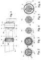
- phase conductors 1 of the cable will not be diverted apart for connection under parallel terminals; instead, they are left in their natural positions and inserted unbent into a purpose-designed connector having a concentric structure, wherein the individual phase conductors 1 are disposed into circularly symmetrical segments of 120°.
- the bottom in each segment terminal of the connector is shaped into a contact terminal 2 which is suited to make electrical contact with a phase conductor 1 and is continued as an isolated bar in the connector body and is finally connected to an inverter drive using appropriate means.
- the stripped lengths of the phase conductors 1 are radially compressed toward each other by means of a clamp 5 resembling a conventional hose clamp so as to provide good electrical contact between the phase conductors 1 and the segment terminals 2.
- Clamp means comprise a clamp ring 7 and a clamp 5 proper.
- insulation pieces 4 and springed elements 6 Between the clamp 7 and the phase conductors 1 are adapted insulation pieces 4 and springed elements 6.
- the springed elements find use in the connection of aluminium conductor cables.
- the springed element 6 is a wave plate of spring steel to be placed between the clamp 7 and the insulation piece 4.
- the phase conductors 1 inside the connector are isolated from each other by means of a star-shaped dividing insulation piece 3 keeping the phase conductors 1 separate in their segments.
- the EMI shield housing can be appropriately called the receptacle of the connector.
Landscapes
- Processing Of Terminals (AREA)
- Coupling Device And Connection With Printed Circuit (AREA)
- Manufacturing Of Electrical Connectors (AREA)
- Cable Accessories (AREA)
Claims (6)
- Steckverbinder für ein Dreiphasenkabel, bestehend aus konzentrischen, segmentartig angeordneten Phasenleiter (1) mit umgebenden Isolierstrukturen (11) und aus einem die Phasenleiter einschliessenden konzentrischen Erdleiter (8), dadurch gekennzeichnet, dassdie Phasenleiter (1) innen im Steckverbinder mittels eines sternförmigen Isoliertrennelementes (3) gegeneinander isoliert sind, das die Trennung der Phasenleiter (1) in ihren Segementen gewährleistet,die Phasenklemmen (2) des Steckverbinders auf den Segmentböden dieses Isoliertrennelementes (3) angeordnet sind,der Steckverbinder weiterhin geeignete Klemmmittel (5, 7) zum Anpressen der Phasenleiter (1) gegen die Phasenklemmen (2) umfasst, undder Steckverbinder noch ein Endstück (10) aufweist, auf dem der Erdleiter (8) nach hinten abgebogen ist und mit Hilfe dessen der Steckverbinder in einer Aufnahme mechanisch verriegelt werden kann.
- Steckverbinder nach Anspruch 1, dadurch gekennzeichnet, dass die Klemmmittel einen Klemmring (7) und eine eigentliche Klemmbüchse (5) umfassen.
- Verfahren zur Herstellung eines Steckverbinders für ein Dreiphasenkabel, bestehend aus konzentrischen, segmentartig angeordneten Phasenleiter (1) mit umgebenden Isolierstrukturen (11) und aus einem die Phasenleiter einschliessenden konzentrischen Erdleiter (8), Verfahren, bei welchem die Phasenleiter (1) mit elektrischen Klemmen (2) elektrisch verbunden werden, welche mit einer elektrischen Last in Verbindung stehen, wobei das den Erdleiter (8) umgebenden Isoliermaterial (9) am Kabelende abisoliert ist ; dadurch gekennzeichnet, dassein Endstück (10) aus Stahl auf den Erdleiter (8) an dessen Ende montiert wird, auf dem sämtliche getrennte Kupferdrähte des Erdleiters (8) nach hinten abgebogen werden und die Drähte an dem Punkt, wo das Endstrück (10) gegen die Plastikhülle des Isoliermaterials (9) anliegt, abgeschnitten werden,die Abdeckisolierung (11) der Phasenleiter entfernt wird und die Enden der Phasenleiter (1) abisoliert werden,das abisolierte Kabelende mit den Klemmen des Segmentes so tief in den Steckverbinder eingedrückt wird, damit das Endstrück (10) des Erdleiters (8) auf die Mitte des Durchführungsflansches der Struktur der Steckverbinderaufnahme ausgerichtet wird,die Phasenleiter (1) mit Hilfe der Klemmmittel (5) gegen die Klemmen (2) des Segmentes gedrückt werden,die Phasenleiter (1) innen im Steckverbinder mittels eines sternförmigen Isoliertrennelementes (3) gegeneinander isoliert sind, welches die Phasenleiter (1) in ihren Segementen voneinander trennt, undschliesslich der Steckverbinder in der Aufnahme befestigt wird, so dass der Erdleiter (8) des Kabels gegen den Durchführungsflansch angedrückt bleibt, wodurch eine sichere elektrische Verbindung und eine gute Zugentlastung hergestellt wird.
- Verfahren nach Anspruch 3, dadurch gekennzeichnet, dass die Isolierung des Erdleiters (8) über eine Länge von ca. 50 bis 150 mm, vorteilhaft ca. 90 mm, entfernt wird.
- Verfahren nach Anspruch 3, dadurch gekennzeichnet, dass die Isolierung (11) des Phasenleiters (1) über eine Länge von ca. 5 bis 50 mm, vorteilhaft ca. 20 mm, entfernt wird.
- Verfahren nach Anspruch 3 zur Fertigung des Steckverbinders für ein Aluminiumkabel, dadurch gekennzeichnet, dass Oxyd von den Innenflächen der Phasenleiter (1) in bekannter Weise durch Aufbringen von Fett, falls erforderlich, entfernt wird.
Applications Claiming Priority (3)
| Application Number | Priority Date | Filing Date | Title |
|---|---|---|---|
| FI945863 | 1994-12-13 | ||
| FI945863A FI97175C (fi) | 1994-12-13 | 1994-12-13 | Liitin kolmivaiheisen kaapelin liittämiseksi sekä liittimen valmistusmenetelmä |
| PCT/FI1995/000628 WO1996019016A1 (en) | 1994-12-13 | 1995-11-14 | Connector for connecting a three-phase cable and manufacturing method of the connector |
Publications (2)
| Publication Number | Publication Date |
|---|---|
| EP0797850A1 EP0797850A1 (de) | 1997-10-01 |
| EP0797850B1 true EP0797850B1 (de) | 1999-05-19 |
Family
ID=8541970
Family Applications (1)
| Application Number | Title | Priority Date | Filing Date |
|---|---|---|---|
| EP95937911A Expired - Lifetime EP0797850B1 (de) | 1994-12-13 | 1995-11-14 | Steckverbinder zum verbinden eines dreiphasigen kabels und herstellungsverfahren für diesen steckverbinder |
Country Status (8)
| Country | Link |
|---|---|
| US (1) | US5952613A (de) |
| EP (1) | EP0797850B1 (de) |
| JP (1) | JP3059762B2 (de) |
| KR (1) | KR100288565B1 (de) |
| AU (1) | AU3873795A (de) |
| DE (1) | DE69509795T2 (de) |
| FI (1) | FI97175C (de) |
| WO (1) | WO1996019016A1 (de) |
Families Citing this family (3)
| Publication number | Priority date | Publication date | Assignee | Title |
|---|---|---|---|---|
| US6227881B1 (en) * | 1999-12-06 | 2001-05-08 | The Jpm Company | Cable management coupling and shielding interconnect system and method |
| US6572416B2 (en) | 2001-11-05 | 2003-06-03 | Ballard Power Systems Corporation | Three-phase connector for electric vehicle drivetrain |
| WO2011076819A2 (en) * | 2009-12-24 | 2011-06-30 | Fci | Cable junction |
Family Cites Families (10)
| Publication number | Priority date | Publication date | Assignee | Title |
|---|---|---|---|---|
| US1904162A (en) * | 1930-08-13 | 1933-04-18 | Milliken Humphreys | Electrical cable |
| US2538019A (en) * | 1945-10-29 | 1951-01-16 | Int Standard Electric Corp | Method of making multicore electrical conductors |
| US3739076A (en) * | 1972-04-17 | 1973-06-12 | L Schwartz | Electrical cable terminating and grounding connector |
| US3830957A (en) * | 1973-08-20 | 1974-08-20 | Amex Syst Inc | Grounding device for shielded electrical cable |
| US4022966A (en) * | 1976-06-16 | 1977-05-10 | I-T-E Imperial Corporation Efcor Division | Ground connector |
| US4243290A (en) * | 1978-10-30 | 1981-01-06 | Williams Robert A | Shield termination means for electrical connector |
| US4420202A (en) * | 1981-09-10 | 1983-12-13 | Pemco Corporation | Plural phase cable couplers |
| DE3243384C1 (de) * | 1982-11-24 | 1984-04-19 | Minnesota Mining and Manufacturing Co., 55101 Saint Paul, Minn. | Elektrische Mehrphasen-Abzweigklemme |
| DE3330627C2 (de) * | 1983-02-25 | 1990-03-08 | Karl Pfisterer Elektrotechnische Spezialartikel Gmbh & Co Kg, 7000 Stuttgart | Klemme |
| US4921449A (en) * | 1989-04-03 | 1990-05-01 | Electro Adapter, Inc. | Shield connections for electrical cable connector |
-
1994
- 1994-12-13 FI FI945863A patent/FI97175C/fi not_active IP Right Cessation
-
1995
- 1995-11-14 WO PCT/FI1995/000628 patent/WO1996019016A1/en not_active Ceased
- 1995-11-14 JP JP8518295A patent/JP3059762B2/ja not_active Expired - Lifetime
- 1995-11-14 AU AU38737/95A patent/AU3873795A/en not_active Abandoned
- 1995-11-14 DE DE69509795T patent/DE69509795T2/de not_active Expired - Lifetime
- 1995-11-14 US US08/836,321 patent/US5952613A/en not_active Expired - Lifetime
- 1995-11-14 EP EP95937911A patent/EP0797850B1/de not_active Expired - Lifetime
- 1995-11-14 KR KR1019970703964A patent/KR100288565B1/ko not_active Expired - Lifetime
Also Published As
| Publication number | Publication date |
|---|---|
| AU3873795A (en) | 1996-07-03 |
| JP3059762B2 (ja) | 2000-07-04 |
| FI97175B (fi) | 1996-07-15 |
| EP0797850A1 (de) | 1997-10-01 |
| FI97175C (fi) | 1996-10-25 |
| DE69509795T2 (de) | 1999-12-16 |
| DE69509795D1 (de) | 1999-06-24 |
| FI945863A0 (fi) | 1994-12-13 |
| KR980700705A (ko) | 1998-03-30 |
| US5952613A (en) | 1999-09-14 |
| JPH10510663A (ja) | 1998-10-13 |
| KR100288565B1 (ko) | 2001-05-02 |
| WO1996019016A1 (en) | 1996-06-20 |
Similar Documents
| Publication | Publication Date | Title |
|---|---|---|
| US5711686A (en) | System for terminating the shield of a high speed cable | |
| US4822956A (en) | Coaxial cable | |
| TW326582B (en) | System for terminating the shield of high speed cables(3) | |
| CA2186663A1 (en) | Two-piece lead seal pothead connector | |
| CA2219668A1 (en) | Connecting clamp for electrical conductors | |
| EP0125760A1 (de) | Stecker mit abschirmender Umhüllung | |
| EP0429962B1 (de) | Verbinder für mehradriges Kabel und Verbindungsverfahren | |
| US5646370A (en) | Permanent attachment of grounding wire | |
| US4468080A (en) | Cable shield termination means for plug and receptacle connectors | |
| US2901528A (en) | Wire connector | |
| US5952613A (en) | Connector for connecting a three-phase cable and manufacturing method of the connector | |
| US5151050A (en) | Cable assembly | |
| CA2013702C (en) | Connector for electrical conductors having similar or different cross-sectional shapes | |
| EP0429961A1 (de) | Verbinder fÀ¼r mehradriges Kabel und Verbindungsverfahren | |
| JP2020503693A (ja) | サーマルプロテクタ | |
| GB2052891A (en) | Method of attaching a contact element to an electric line | |
| US4562518A (en) | Light assembly for use on vehicles | |
| US4334726A (en) | Bonding device | |
| JPH0525137Y2 (de) | ||
| US4068914A (en) | Connector device for telephone terminals or housings | |
| TW293958B (de) | ||
| US4260848A (en) | Ready access closure for communication cables | |
| RU2043679C1 (ru) | Устройство для соединения электрических проводов | |
| JPH0778663A (ja) | シールド電線のアース方法と、それに用いるアース用接続子 | |
| JP3625525B2 (ja) | フラットケーブルの端末部形成方法 |
Legal Events
| Date | Code | Title | Description |
|---|---|---|---|
| PUAI | Public reference made under article 153(3) epc to a published international application that has entered the european phase |
Free format text: ORIGINAL CODE: 0009012 |
|
| 17P | Request for examination filed |
Effective date: 19970429 |
|
| AK | Designated contracting states |
Kind code of ref document: A1 Designated state(s): DE FR GB IT |
|
| 17Q | First examination report despatched |
Effective date: 19980403 |
|
| GRAG | Despatch of communication of intention to grant |
Free format text: ORIGINAL CODE: EPIDOS AGRA |
|
| GRAG | Despatch of communication of intention to grant |
Free format text: ORIGINAL CODE: EPIDOS AGRA |
|
| GRAH | Despatch of communication of intention to grant a patent |
Free format text: ORIGINAL CODE: EPIDOS IGRA |
|
| GRAH | Despatch of communication of intention to grant a patent |
Free format text: ORIGINAL CODE: EPIDOS IGRA |
|
| GRAA | (expected) grant |
Free format text: ORIGINAL CODE: 0009210 |
|
| AK | Designated contracting states |
Kind code of ref document: B1 Designated state(s): DE FR GB IT |
|
| REF | Corresponds to: |
Ref document number: 69509795 Country of ref document: DE Date of ref document: 19990624 |
|
| ET | Fr: translation filed | ||
| PLBE | No opposition filed within time limit |
Free format text: ORIGINAL CODE: 0009261 |
|
| STAA | Information on the status of an ep patent application or granted ep patent |
Free format text: STATUS: NO OPPOSITION FILED WITHIN TIME LIMIT |
|
| 26N | No opposition filed | ||
| REG | Reference to a national code |
Ref country code: GB Ref legal event code: IF02 |
|
| PGFP | Annual fee paid to national office [announced via postgrant information from national office to epo] |
Ref country code: FR Payment date: 20101130 Year of fee payment: 16 |
|
| PGFP | Annual fee paid to national office [announced via postgrant information from national office to epo] |
Ref country code: DE Payment date: 20101119 Year of fee payment: 16 |
|
| PGFP | Annual fee paid to national office [announced via postgrant information from national office to epo] |
Ref country code: GB Payment date: 20101118 Year of fee payment: 16 Ref country code: IT Payment date: 20101126 Year of fee payment: 16 |
|
| GBPC | Gb: european patent ceased through non-payment of renewal fee |
Effective date: 20111114 |
|
| REG | Reference to a national code |
Ref country code: FR Ref legal event code: ST Effective date: 20120731 |
|
| PG25 | Lapsed in a contracting state [announced via postgrant information from national office to epo] |
Ref country code: IT Free format text: LAPSE BECAUSE OF NON-PAYMENT OF DUE FEES Effective date: 20111114 |
|
| REG | Reference to a national code |
Ref country code: DE Ref legal event code: R119 Ref document number: 69509795 Country of ref document: DE Effective date: 20120601 |
|
| PG25 | Lapsed in a contracting state [announced via postgrant information from national office to epo] |
Ref country code: GB Free format text: LAPSE BECAUSE OF NON-PAYMENT OF DUE FEES Effective date: 20111114 |
|
| PG25 | Lapsed in a contracting state [announced via postgrant information from national office to epo] |
Ref country code: FR Free format text: LAPSE BECAUSE OF NON-PAYMENT OF DUE FEES Effective date: 20111130 |
|
| PG25 | Lapsed in a contracting state [announced via postgrant information from national office to epo] |
Ref country code: DE Free format text: LAPSE BECAUSE OF NON-PAYMENT OF DUE FEES Effective date: 20120601 |