EP0797839B1 - Entladungslampe, insbesondere für fahrzeugbeleuchtungssysteme - Google Patents
Entladungslampe, insbesondere für fahrzeugbeleuchtungssysteme Download PDFInfo
- Publication number
- EP0797839B1 EP0797839B1 EP96929181A EP96929181A EP0797839B1 EP 0797839 B1 EP0797839 B1 EP 0797839B1 EP 96929181 A EP96929181 A EP 96929181A EP 96929181 A EP96929181 A EP 96929181A EP 0797839 B1 EP0797839 B1 EP 0797839B1
- Authority
- EP
- European Patent Office
- Prior art keywords
- discharge lamp
- cap
- lamp according
- insulating material
- longitudinal axis
- Prior art date
- Legal status (The legal status is an assumption and is not a legal conclusion. Google has not performed a legal analysis and makes no representation as to the accuracy of the status listed.)
- Expired - Lifetime
Links
- 239000011810 insulating material Substances 0.000 claims description 8
- 239000004020 conductor Substances 0.000 claims description 4
- 239000012777 electrically insulating material Substances 0.000 claims description 4
- 239000004697 Polyetherimide Substances 0.000 claims description 3
- 239000004033 plastic Substances 0.000 claims description 3
- 229920003023 plastic Polymers 0.000 claims description 3
- 229920001601 polyetherimide Polymers 0.000 claims description 3
- 229920000265 Polyparaphenylene Polymers 0.000 claims 1
- UCKMPCXJQFINFW-UHFFFAOYSA-N Sulphide Chemical compound [S-2] UCKMPCXJQFINFW-UHFFFAOYSA-N 0.000 claims 1
- -1 polyphenylene Polymers 0.000 claims 1
- 239000000463 material Substances 0.000 description 4
- 230000001629 suppression Effects 0.000 description 3
- 239000004734 Polyphenylene sulfide Substances 0.000 description 2
- 239000003990 capacitor Substances 0.000 description 2
- 229910001507 metal halide Inorganic materials 0.000 description 2
- 150000005309 metal halides Chemical class 0.000 description 2
- 239000000203 mixture Substances 0.000 description 2
- 229920000069 polyphenylene sulfide Polymers 0.000 description 2
- RYGMFSIKBFXOCR-UHFFFAOYSA-N Copper Chemical compound [Cu] RYGMFSIKBFXOCR-UHFFFAOYSA-N 0.000 description 1
- 229920002873 Polyethylenimine Polymers 0.000 description 1
- 230000015572 biosynthetic process Effects 0.000 description 1
- 239000000919 ceramic Substances 0.000 description 1
- 229910052802 copper Inorganic materials 0.000 description 1
- 239000010949 copper Substances 0.000 description 1
- 230000001419 dependent effect Effects 0.000 description 1
- 238000011161 development Methods 0.000 description 1
- 230000018109 developmental process Effects 0.000 description 1
- 230000000694 effects Effects 0.000 description 1
- 230000005684 electric field Effects 0.000 description 1
- 239000011261 inert gas Substances 0.000 description 1
- 238000002347 injection Methods 0.000 description 1
- 239000007924 injection Substances 0.000 description 1
- 238000001746 injection moulding Methods 0.000 description 1
- QSHDDOUJBYECFT-UHFFFAOYSA-N mercury Chemical compound [Hg] QSHDDOUJBYECFT-UHFFFAOYSA-N 0.000 description 1
- 229910052753 mercury Inorganic materials 0.000 description 1
- 229910052751 metal Inorganic materials 0.000 description 1
- 239000002184 metal Substances 0.000 description 1
- 239000000126 substance Substances 0.000 description 1
- 229910052724 xenon Inorganic materials 0.000 description 1
- FHNFHKCVQCLJFQ-UHFFFAOYSA-N xenon atom Chemical compound [Xe] FHNFHKCVQCLJFQ-UHFFFAOYSA-N 0.000 description 1
Images
Classifications
-
- H—ELECTRICITY
- H01—ELECTRIC ELEMENTS
- H01J—ELECTRIC DISCHARGE TUBES OR DISCHARGE LAMPS
- H01J61/00—Gas-discharge or vapour-discharge lamps
- H01J61/02—Details
- H01J61/56—One or more circuit elements structurally associated with the lamp
Definitions
- the invention is based on a discharge lamp, especially for vehicle lighting systems, according to the Genus of claim 1.
- Such a discharge lamp is described in DE 36 03 743 A1 known.
- This discharge lamp has a discharge vessel on, in which two electrodes are arranged. Also points the discharge lamp has a base made of electrically insulating Material through which electrical leads to the Electrodes are guided.
- Discharge lamps usually operated with high voltage and it has shown that in their operation electromagnetic interference spread along the leads to the lamp.
- the suppression circuit points among other things, a capacitor connected in parallel between the supply lines to the discharge lamp is switched. This additional interference suppression circuit, however, represents a major one Effort and causes additional costs.
- the discharge lamp according to the invention with the features of Claim 1 has the advantage that with a few additional components in the base of the discharge lamp capacitive component is integrated, through which the Propagation of electromagnetic interference over the Leads of the lamp prevented or at least weakened is.
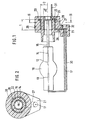
- FIG. 1 shows a discharge lamp in one Longitudinal section and Figure 2, the discharge lamp in one Cross section along line II-II in Figure 1.
- a discharge lamp shown in Figures 1 and 2 for Vehicle lighting systems, in particular Motor vehicle headlight, has a discharge vessel 10, protrude into the two electrodes 12 and 13.
- the electrodes 12, 13 each other in the direction of the longitudinal axis 14 of the lamp arranged opposite each other.
- Arrange electrodes so that they are transverse to the longitudinal axis 14 of the Lamp facing each other.
- the discharge vessel 10 contain a mixture of different substances that Applying a voltage between the electrodes 12, 13 for Light emission can be stimulated.
- mercury under high pressure and optionally a metal halide or a mixture of contain various metal halides.
- an inert gas may be contained in the discharge vessel, for example xenon.
- An electrical feed line 16 is provided with each electrode 12, 13 or 17 connected to a base 20 of the Discharge lamp leads.
- the one facing the base 20 Lead 12 connected to lead 16 is approximately in the middle of Discharge vessel 10 and approximately parallel to the longitudinal axis 14 of the Lamp arranged and the other electrode 13 connected supply line 17 is off-center and approximately parallel arranged to the longitudinal axis 14 of the lamp.
- the base 20 of the Discharge lamp consists of electrically insulating Material, for example plastic or ceramic.
- a component 22 connected from electrically conductive material, the for example as a round at least on its outer circumference Sleeve is formed, the coaxial to the longitudinal axis 14 of the Lamp is arranged.
- the component 22 is at least on its outer periphery of the insulating material of the base 20 enclosed.
- the component 22 points in the direction of the longitudinal axis 14 of the discharge lamp a length 1 and based on the Longitudinal axis 14 a radius r1.
- the base 20 With the end of the other feed line arranged in the base 20 17 is also a component 26 made of electrically conductive Material connected.
- the base 20 has a widening 21, in which the end of the feed line 17 is arranged.
- the Component 26 is essentially annular and has a connecting section 27, via which it connects to the End of the lead 17 is connected and an annular Section 28, which surrounds the component 22.
- the annular portion 28 of the component 26 coaxial with Component 22 and thus arranged to the longitudinal axis 14, so that the distance between the outer circumference of the component 22 and the inner circumference of section 28 is constant.
- annular portion 28 of component 26 is in the direction of Longitudinal axis 14 of the lamp viewed in the same area arranged like the component 22 and extends preferably over the same length 1 as the component 22. Der annular section 28 of component 26 is thus in At least viewed in the direction of the longitudinal axis 14 of the lamp arranged approximately congruent with the component 22. Of the annular section 28 of the component 26 is on a Radius r2 arranged about the longitudinal axis 14 and preferably trained over its entire circumference, can however also be interrupted. On his from the discharge tube 10 pointing end, the annular portion 28 of the Component 26 a radially to the longitudinal axis 14 to the outside projecting edge 29 on. The component 26 is almost completely of the insulating material of the base 20 enclosed.
- the feed line 17 can in its outside of Base 20 arranged area to the electrode 13 with be provided with an electrically insulating sheath 30.
- a capacitive component with a predetermined capacitance can be formed by correspondingly varying the dimensions 1 and / or r1 and / or r2.
- the capacity can be changed in a simple manner, in particular by varying the length 1.
- PEI polyetherimide
- ⁇ r dielectric constant
- a capacitance of approximately 5.9 pF results for a length 1 of 8 mm, a capacitance of 7.4 pF for a length 1 of 10 mm and a length 1 of 12 mm a capacity of 8.9 pF.
- Polyphenylene sulfide, PPS can also be used as the material for the base 20.
- connection elements are on the discharge vessel 10 opposite side of the base 20 arranged Connection elements connected.
- a socket 31 or a pin be connected and with the off-center feed line 17 Conductor ring 32.
- a plug part, not shown, are placed on the has corresponding counter-connection elements.
- the base 20 of the discharge lamp is preferably by Injection molding manufactured, the components 22,26 in their predetermined assignment to each other in an injection mold be introduced and then with the electrical overmolded insulating plastic material of the base become.
- Formation of components 22 and 26 can also plate-shaped design of these components can be provided.
- 16.17 is also with each supply line plate-shaped electrically conductive component connected, the two components through the insulating material of the Base 20 are separated from each other and one Form plate capacitor.
Landscapes
- Non-Portable Lighting Devices Or Systems Thereof (AREA)
- Common Detailed Techniques For Electron Tubes Or Discharge Tubes (AREA)
- Discharge Lamps And Accessories Thereof (AREA)
Description
- εr
- die Dielektrizitätskonstante des isolierenden Materials des Sockels,
- ε0
- die elektrische Feldkonstante, die 8,854 10-12 F/m beträgt,
- r1
- der Radius des inneren Bauteils 22,
- r2
- der Radius des ringförmigen Abschnitts 28 des äußeren Bauteils 26,
- l
- die Länge der Bauteile 22,28
Claims (9)
- Entladungslampe, insbesondere für Fahrzeubeleuchtungssysteme, mit einem Entladungsgefäß (10), in das wenigstens zwei Elektroden (12,13) hineinragen, und mit einem Sockel (20) aus elektrisch isolierendem Material, wobei elektrische Zuleitungen (16,17) zu den Elektroden (12,13) durch den Sockel (20) geführt sind, dadurch gekennzeichnet, daß mit jeder Zuleitung (16,17) wenigstens ein Bauteil (22,26) aus elektrisch leitfähigem Material verbunden ist, das im Sockel (20) angeordnet ist, wobei die verschiedenen Zuleitungen (16,17) zugeordneten Bauteile (22,26) durch das isolierende Material des Sockels (20) elektrisch voneinander getrennt sind und zusammen mit dem isolierenden Material des Sockels (20) ein kapazitives Bauelement bilden.
- Entladungslampe nach Anspruch 1, dadurch gekennzeichnet, daß die Bauteile (22,26) zumindest teilweise vom isolierenden Material des Sockels (20) umschlossen sind.
- Entladungslampe nach Anspruch 1 oder 2, dadurch gekennzeichnet, daß ein mit einer der Zuleitungen (16) verbundenes erstes Bauteil (22) eine etwa zylinderförmige Außenform aufweist und daß ein mit einer anderen der Zuleitungen (17) verbundenes zweites Bauteil (26) einen zumindest annähernd ringförmigen Abschnitt (28) aufweist, der das erste Bauteil (22) mit Abstand umgibt.
- Entladungslampe nach Anspruch 3, dadurch gekennzeichnet, daß das erste Bauteil (22) und der ringförmige Abschnitt (28) des zweiten Bauteils (26) zumindest annähernd koaxial angeordnet sind.
- Entladungslampe nach Anspruch 3 oder 4, dadurch gekennzeichnet, daß eine Elektrode (12) und die mit dieser verbundene Zuleitung (16) etwa mittig bezüglich der Lampenlängsachse (14) angeordnet ist und mit dieser Zuleitung (16) das erste Bauteil (22) verbunden ist und daß eine andere Elektrode (13) und die mit dieser verbundene Zuleitung (17) außermittig bezüglich der Lampenlängsachse (14) angeordnet ist und mit dieser Zuleitung (17) das zweite Bauteil (26) verbunden ist.
- Entladungslampe nach einem der Ansprüche 3 bis 5, dadurch gekennzeichnet, daß die beiden Bauteile (22,26) in Richtung der Lampenlängsachse (14) zumindest annähernd deckungsgleich angeordnet sind.
- Entladungslampe nach einem der vorstehenden Ansprüche, dadurch gekennzeichnet, daß der Sockel (20) aus Kunststoff besteht.
- Entladungslampe nach Anspruch 7, dadurch gekennzeichnet, daß der Sockel (20) aus Polyetherimid besteht.
- Entladungslampe nach Anspruch 7, dadurch gekennzeichnet, daß der Sockel (20) aus Polyphenylensulfid besteht.
Applications Claiming Priority (3)
| Application Number | Priority Date | Filing Date | Title |
|---|---|---|---|
| DE19538064A DE19538064A1 (de) | 1995-10-13 | 1995-10-13 | Entladungslampe, insbesondere für Fahrzeugbeleuchtungssysteme |
| DE19538064 | 1995-10-13 | ||
| PCT/DE1996/001703 WO1997015064A1 (de) | 1995-10-13 | 1996-09-11 | Entladungslampe, insbesondere für fahrzeugbeleuchtungssysteme |
Publications (2)
| Publication Number | Publication Date |
|---|---|
| EP0797839A1 EP0797839A1 (de) | 1997-10-01 |
| EP0797839B1 true EP0797839B1 (de) | 1999-12-01 |
Family
ID=7774697
Family Applications (1)
| Application Number | Title | Priority Date | Filing Date |
|---|---|---|---|
| EP96929181A Expired - Lifetime EP0797839B1 (de) | 1995-10-13 | 1996-09-11 | Entladungslampe, insbesondere für fahrzeugbeleuchtungssysteme |
Country Status (7)
| Country | Link |
|---|---|
| US (1) | US5889360A (de) |
| EP (1) | EP0797839B1 (de) |
| JP (1) | JPH10510948A (de) |
| KR (1) | KR100437299B1 (de) |
| DE (2) | DE19538064A1 (de) |
| ES (1) | ES2140891T3 (de) |
| WO (1) | WO1997015064A1 (de) |
Families Citing this family (6)
| Publication number | Priority date | Publication date | Assignee | Title |
|---|---|---|---|---|
| US6201348B1 (en) * | 1998-02-20 | 2001-03-13 | Osram Sylvania Inc. | Capacitive coupling starting aid for metal halide lamp |
| GB9825296D0 (en) * | 1998-11-18 | 1999-01-13 | Microlights Ltd | A improvement to electrical lamps |
| KR20050115917A (ko) | 2003-03-18 | 2005-12-08 | 코닌클리즈케 필립스 일렉트로닉스 엔.브이. | 가스 방전 램프 |
| FR2862744B1 (fr) * | 2003-11-21 | 2006-09-29 | Valeo Vision | Systeme de fixation d'une source lumineuse sur une contrepartie d'un projecteur de vehicule automobile et procede de mise en oeuvre |
| US7270453B2 (en) * | 2004-12-21 | 2007-09-18 | General Electric Company | Heat resistant plastic lamp components and methods of forming |
| CN102714128B (zh) * | 2010-01-28 | 2016-04-20 | 皇家飞利浦电子股份有限公司 | 具有减小高度的燃烧器和制造燃烧器的方法 |
Family Cites Families (8)
| Publication number | Priority date | Publication date | Assignee | Title |
|---|---|---|---|---|
| NL7610451A (nl) * | 1976-09-21 | 1978-03-23 | Philips Nv | Ontladingslamp. |
| DE3343914C2 (de) * | 1983-12-05 | 1986-04-03 | May & Christe Gmbh, Transformatorenwerke, 6370 Oberursel | Adapter für Gasentladungslampen bzw. Niederspannungslampen |
| US4751435A (en) * | 1984-12-13 | 1988-06-14 | Gte Laboratories Incorporated | Dual cathode beam mode fluorescent lamp with capacitive ballast |
| DE3603743A1 (de) * | 1986-02-06 | 1987-08-13 | Patent Treuhand Ges Fuer Elektrische Gluehlampen Mbh | Hochdruckentladungslampe fuer die verwendung in kraftfahrzeugscheinwerfern |
| US5039904A (en) * | 1989-09-28 | 1991-08-13 | General Electric Company | Mount for miniature arc lamp |
| US5059864A (en) * | 1989-12-22 | 1991-10-22 | Gte Products Corporation | Negative glow lamp |
| US5389856A (en) * | 1992-01-17 | 1995-02-14 | U.S. Philips Corporation | High-pressure discharge lamp with an integral fuse-capacitor component |
| DE4310307B4 (de) * | 1993-03-30 | 2004-10-14 | Robert Bosch Gmbh | Scheinwerfer für Fahrzeuge |
-
1995
- 1995-10-13 DE DE19538064A patent/DE19538064A1/de not_active Withdrawn
-
1996
- 1996-09-11 KR KR1019970703424A patent/KR100437299B1/ko not_active Expired - Fee Related
- 1996-09-11 DE DE59603781T patent/DE59603781D1/de not_active Expired - Fee Related
- 1996-09-11 ES ES96929181T patent/ES2140891T3/es not_active Expired - Lifetime
- 1996-09-11 US US08/860,352 patent/US5889360A/en not_active Expired - Fee Related
- 1996-09-11 WO PCT/DE1996/001703 patent/WO1997015064A1/de not_active Ceased
- 1996-09-11 EP EP96929181A patent/EP0797839B1/de not_active Expired - Lifetime
- 1996-09-11 JP JP9515397A patent/JPH10510948A/ja not_active Ceased
Also Published As
| Publication number | Publication date |
|---|---|
| US5889360A (en) | 1999-03-30 |
| KR987000677A (ko) | 1998-03-30 |
| KR100437299B1 (ko) | 2004-09-04 |
| ES2140891T3 (es) | 2000-03-01 |
| DE59603781D1 (de) | 2000-01-05 |
| EP0797839A1 (de) | 1997-10-01 |
| JPH10510948A (ja) | 1998-10-20 |
| WO1997015064A1 (de) | 1997-04-24 |
| DE19538064A1 (de) | 1997-04-17 |
Similar Documents
| Publication | Publication Date | Title |
|---|---|---|
| DE4310307B4 (de) | Scheinwerfer für Fahrzeuge | |
| DE2830552C2 (de) | Kurzschlußsicherung für elektrische Zünder | |
| DE3447478A1 (de) | Pyrotechnische zuendkapsel mit koaxialstecker | |
| DE19610388A1 (de) | Zündeinrichtung für eine Entladungslampe | |
| EP0886882B1 (de) | Gasentladungslampe, insbesondere für kraftfahrzeug-scheinwerfer | |
| EP0238520B1 (de) | Zündkerze mit gleitfunkenstrecke | |
| DE19927233A1 (de) | Glas-Metall-Durchführung | |
| EP1198823A1 (de) | Gasentladungslampe mit zündhilfselektroden, insbesondere für kraftfahrzeugscheinwerfer | |
| EP1470620B1 (de) | Polklemme | |
| DE2654092A1 (de) | Zuendkerze | |
| DE19538064A1 (de) | Entladungslampe, insbesondere für Fahrzeugbeleuchtungssysteme | |
| EP0378963B1 (de) | Funkenstreckenbauelement für geschirmte Anordnung | |
| EP1334510B1 (de) | Dielektrische barrieren-entladungslampe | |
| DE3415625A1 (de) | Elektrisches zuendelement mit soll-funkenstrecke | |
| DE102007025368B4 (de) | Anzündereinheit für einen Gasgenerator und Gasgenerator | |
| EP0728986A1 (de) | Stecker zur Kontaktierung einer Gasentladungslampe | |
| EP0567959A2 (de) | Elektrisches Zündelement mit Soll-Entladungsstrecke | |
| EP1511132B1 (de) | Lampensockel für eine Hochdruckentladungslampe und Hochdruckentladungslampe | |
| WO2001031670A1 (de) | Entladungslampe | |
| EP3439115A1 (de) | Elektrischer steckverbinder | |
| CH682282A5 (de) | ||
| DE10018411B4 (de) | Zündvorrichtung für pyrotechnische Gasgeneratoren | |
| DE4001538A1 (de) | Vorglueheinrichtung fuer dieselmotoren | |
| DE102004056004A1 (de) | Hochdruckentladungslampe | |
| DE4141587A1 (de) | Scheinwerfer fuer kraftfahrzeuge |
Legal Events
| Date | Code | Title | Description |
|---|---|---|---|
| PUAI | Public reference made under article 153(3) epc to a published international application that has entered the european phase |
Free format text: ORIGINAL CODE: 0009012 |
|
| AK | Designated contracting states |
Kind code of ref document: A1 Designated state(s): DE ES FR GB IT |
|
| 17P | Request for examination filed |
Effective date: 19971024 |
|
| GRAG | Despatch of communication of intention to grant |
Free format text: ORIGINAL CODE: EPIDOS AGRA |
|
| 17Q | First examination report despatched |
Effective date: 19990125 |
|
| GRAG | Despatch of communication of intention to grant |
Free format text: ORIGINAL CODE: EPIDOS AGRA |
|
| GRAH | Despatch of communication of intention to grant a patent |
Free format text: ORIGINAL CODE: EPIDOS IGRA |
|
| GRAH | Despatch of communication of intention to grant a patent |
Free format text: ORIGINAL CODE: EPIDOS IGRA |
|
| GRAA | (expected) grant |
Free format text: ORIGINAL CODE: 0009210 |
|
| AK | Designated contracting states |
Kind code of ref document: B1 Designated state(s): DE ES FR GB IT |
|
| REF | Corresponds to: |
Ref document number: 59603781 Country of ref document: DE Date of ref document: 20000105 |
|
| ET | Fr: translation filed | ||
| ITF | It: translation for a ep patent filed | ||
| GBT | Gb: translation of ep patent filed (gb section 77(6)(a)/1977) |
Effective date: 20000207 |
|
| REG | Reference to a national code |
Ref country code: ES Ref legal event code: FG2A Ref document number: 2140891 Country of ref document: ES Kind code of ref document: T3 |
|
| PLBE | No opposition filed within time limit |
Free format text: ORIGINAL CODE: 0009261 |
|
| STAA | Information on the status of an ep patent application or granted ep patent |
Free format text: STATUS: NO OPPOSITION FILED WITHIN TIME LIMIT |
|
| 26N | No opposition filed | ||
| REG | Reference to a national code |
Ref country code: GB Ref legal event code: IF02 |
|
| PGFP | Annual fee paid to national office [announced via postgrant information from national office to epo] |
Ref country code: FR Payment date: 20030819 Year of fee payment: 8 |
|
| PGFP | Annual fee paid to national office [announced via postgrant information from national office to epo] |
Ref country code: ES Payment date: 20030826 Year of fee payment: 8 |
|
| PGFP | Annual fee paid to national office [announced via postgrant information from national office to epo] |
Ref country code: GB Payment date: 20030917 Year of fee payment: 8 |
|
| PGFP | Annual fee paid to national office [announced via postgrant information from national office to epo] |
Ref country code: DE Payment date: 20031029 Year of fee payment: 8 |
|
| PG25 | Lapsed in a contracting state [announced via postgrant information from national office to epo] |
Ref country code: GB Free format text: LAPSE BECAUSE OF NON-PAYMENT OF DUE FEES Effective date: 20040911 |
|
| PG25 | Lapsed in a contracting state [announced via postgrant information from national office to epo] |
Ref country code: ES Free format text: LAPSE BECAUSE OF NON-PAYMENT OF DUE FEES Effective date: 20040913 |
|
| PG25 | Lapsed in a contracting state [announced via postgrant information from national office to epo] |
Ref country code: DE Free format text: LAPSE BECAUSE OF NON-PAYMENT OF DUE FEES Effective date: 20050401 |
|
| GBPC | Gb: european patent ceased through non-payment of renewal fee |
Effective date: 20040911 |
|
| PG25 | Lapsed in a contracting state [announced via postgrant information from national office to epo] |
Ref country code: FR Free format text: LAPSE BECAUSE OF NON-PAYMENT OF DUE FEES Effective date: 20050531 |
|
| REG | Reference to a national code |
Ref country code: FR Ref legal event code: ST |
|
| PG25 | Lapsed in a contracting state [announced via postgrant information from national office to epo] |
Ref country code: IT Free format text: LAPSE BECAUSE OF NON-PAYMENT OF DUE FEES;WARNING: LAPSES OF ITALIAN PATENTS WITH EFFECTIVE DATE BEFORE 2007 MAY HAVE OCCURRED AT ANY TIME BEFORE 2007. THE CORRECT EFFECTIVE DATE MAY BE DIFFERENT FROM THE ONE RECORDED. Effective date: 20050911 |
|
| REG | Reference to a national code |
Ref country code: ES Ref legal event code: FD2A Effective date: 20040913 |