US5889360A - Discharge lamp with capacitive socket - Google Patents
Discharge lamp with capacitive socket Download PDFInfo
- Publication number
- US5889360A US5889360A US08/860,352 US86035297A US5889360A US 5889360 A US5889360 A US 5889360A US 86035297 A US86035297 A US 86035297A US 5889360 A US5889360 A US 5889360A
- Authority
- US
- United States
- Prior art keywords
- socket
- components
- insulating material
- component
- discharge lamp
- Prior art date
- Legal status (The legal status is an assumption and is not a legal conclusion. Google has not performed a legal analysis and makes no representation as to the accuracy of the status listed.)
- Expired - Fee Related
Links
- 239000011810 insulating material Substances 0.000 claims abstract description 18
- 239000004020 conductor Substances 0.000 claims description 6
- 239000004697 Polyetherimide Substances 0.000 claims description 3
- 239000004734 Polyphenylene sulfide Substances 0.000 claims description 3
- 239000004033 plastic Substances 0.000 claims description 3
- 229920003023 plastic Polymers 0.000 claims description 3
- 229920001601 polyetherimide Polymers 0.000 claims description 3
- 229920000069 polyphenylene sulfide Polymers 0.000 claims description 3
- 239000012777 electrically insulating material Substances 0.000 abstract description 3
- 239000000463 material Substances 0.000 description 3
- 229910001507 metal halide Inorganic materials 0.000 description 2
- 150000005309 metal halides Chemical class 0.000 description 2
- 239000000203 mixture Substances 0.000 description 2
- RYGMFSIKBFXOCR-UHFFFAOYSA-N Copper Chemical compound [Cu] RYGMFSIKBFXOCR-UHFFFAOYSA-N 0.000 description 1
- 229920002873 Polyethylenimine Polymers 0.000 description 1
- 239000003990 capacitor Substances 0.000 description 1
- 229910010293 ceramic material Inorganic materials 0.000 description 1
- 229910052802 copper Inorganic materials 0.000 description 1
- 239000010949 copper Substances 0.000 description 1
- 230000005684 electric field Effects 0.000 description 1
- 238000002347 injection Methods 0.000 description 1
- 239000007924 injection Substances 0.000 description 1
- 238000001746 injection moulding Methods 0.000 description 1
- 238000005259 measurement Methods 0.000 description 1
- QSHDDOUJBYECFT-UHFFFAOYSA-N mercury Chemical compound [Hg] QSHDDOUJBYECFT-UHFFFAOYSA-N 0.000 description 1
- 229910052753 mercury Inorganic materials 0.000 description 1
- 229910052751 metal Inorganic materials 0.000 description 1
- 239000002184 metal Substances 0.000 description 1
- 239000000126 substance Substances 0.000 description 1
- 229910052724 xenon Inorganic materials 0.000 description 1
- FHNFHKCVQCLJFQ-UHFFFAOYSA-N xenon atom Chemical compound [Xe] FHNFHKCVQCLJFQ-UHFFFAOYSA-N 0.000 description 1
Images
Classifications
-
- H—ELECTRICITY
- H01—ELECTRIC ELEMENTS
- H01J—ELECTRIC DISCHARGE TUBES OR DISCHARGE LAMPS
- H01J61/00—Gas-discharge or vapour-discharge lamps
- H01J61/02—Details
- H01J61/56—One or more circuit elements structurally associated with the lamp
Definitions
- the invention relates to a discharge lamp, in particular for vehicle lighting systems.
- Such a discharge lamp is known from DE 36 03 743 A1.
- This discharge lamp has a discharge vessel with two electrodes arranged inside.
- the discharge lamp has a socket made of electrically insulating material, through which electrical lines are conducted to the electrodes.
- Discharge lamps are commonly operated at high voltage and it has been shown that electromagnetic interference along the electrical lines to the lamp tends to occur during operation.
- DE 43 10 307 it is suggested to place a filter circuit into a housing near the discharge lamp in order to prevent or at least reduce the spreading of electromagnetic interference.
- the filter circuit has a condenser among other things, which is connected in parallel with the electrical lines to the discharge lamp.
- this additional filter circuit represents a large expenditure and creates additional costs.
- the discharge lamp in accordance with the invention has the advantage that with the addition of a few components a capacitively acting component is integrated into the socket of the discharge lamp, by means of which the spreading of electromagnetic interference via the electrical lines to the lamp is prevented or at least reduced.
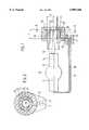
- FIG. 1 shows a discharge lamp in cross-section.
- FIG. 2 shows the discharge lamp in cross-section along line II--II in FIG. 1.
- a discharge lamp for vehicle lighting systems in particular for motor vehicle head lights as shown in FIGS. 1 and 2, has a discharge vessel 10 with two inward extending electrodes 12 and 13.
- the electrodes 12, 13 are arranged opposite each other in the direction of the longitudinal axis 14 of the lamp.
- the discharge vessel 10 contains a mixture of different substances which, when a voltage is applied between the electrodes 12, 13, are excited to output light.
- the discharge vessel 10 contains mercury under high pressure and, if desired, a metal halide, or a mixture of different metal halides.
- the discharge vessel can contain a rare gas, for example xenon.
- An electrical line 16 or 17 which leads to a socket 20 of the discharge lamp is connected to each electrode 12, 13.
- the line 16 connected to the electrode 12 leading to the socket 20 is disposed approximately centrally in respect to the discharge vessel 10 and approximately parallel with the longitudinal axis 14 of the lamp, and the line 17 connected to the other electrode 13 is disposed off center and approximately parallel with the longitudinal axis 14 of the lamp.
- the socket 20 of the discharge lamp is made of an electrically insulating material, for example a plastic or ceramic material.
- a component 22 made of an electrically conductive material is connected with the end of the line 16 arranged in the socket 20, which for example is embodied as a sleeve which is round at least on its exterior, and which is disposed coaxially with the longitudinal axis 14 of the lamp.
- the component 22 is enveloped by the insulating material of the socket 20, at least at its exterior circumference. In the direction of the longitudinal axis 14, the component 22 has a length 1 and a radius of rl in relation to the longitudinal axi
- a component 26 made of an electrically conductive material is also connected with the end of the other line 17 arranged in the socket 20.
- the socket 20 has a widening 21 in which the end of the line 17 has been placed.
- the component 26 is essentially embodied in a ring shape and has a connecting piece 27, by which it is connected to the end of the line 17, and a ring-shaped section 28, which envelops the component 22.
- the ring-shaped section 28 of the component 26 is preferably disposed coaxially with the component 22 and thus with the longitudinal axis 14, so that the distance between the exterior circumference of the component 22 and the interior circumference of the section 28 is constant.
- the ring-shaped section 28 of the component 26 is disposed in the same area as the component 22 and preferably extends over the same length 1 as the component 22.
- the ring-shaped section 28 of the component 26 is disposed at least almost congruently with the component 22.
- the ring-shaped section 28 of the component 26 is disposed on a radius r2 around the longitudinal axis 14, and embodied to be closed over its entire circumference, but can also be designed with breaks.
- the ring shaped section 28 of the component 26 has an edge 29 projecting radially outward in respect to the longitudinal axis 14.
- the component 26 is almost completely enveloped by the insulating material of the socket 20. In its area disposed outside the socket 20 in the direction toward the electrode 13, the line 17 can be provided with an electrically insulating sheath 30.
- the components 22 and 26 are preferably made of metal, for example copper, and are electrically separated from each other by the insulating material of the socket 20 between them.
- the components 22 and 26 generate a capacitive effect by means of the insulating material of the socket 20 and form a capacitive component, which is connected in parallel between the two lines 16 and 17.
- the capacitance C of this component can be determined in accordance with the following equation: ##EQU1## Wherein: ⁇ r is the dielectric constant of the insulating material of the socket,
- ⁇ 0 is the electrical field constant, which is 8.854 10-12 F/m
- r1 is the radius of the interior component 22
- r2 is the radius of the ring shaped section 28 of the exterior 26,
- l is the length of components 22, 28.
- a capacitive component of preset capacitance can be formed. Particularly through variation of the length 1, the capacitance can easily be changed.
- Another usable material for the socket 20 can also be polyphenylene sulfide, PPS.
- Connecting elements arranged on the side of the socket 20 which is opposite from the discharge vessel 10 are connected with the lines 16, 17.
- a plug sleeve 31 or a pin plug can be connected with the centrally located line 16, and a conductor ring 32 with the off center line 17.
- a plug component, not shown, which has corresponding counter connecting elements, can be attached on the socket 20 of the discharge lamp.
- the socket 20 of the discharge lamp is preferably produced by injection molding, wherein the components 22, 26 are placed in predetermined order to each other into an injection mold, and are covered with the electrically insulating plastic material of the socket.
- a plate-shaped embodiment of these components is also possible.
- a plate-shaped electrical conductive component is also connected with each line 16, 17, wherein the two components are separated from each other by the insulating material of the socket 20 and form a plate capacitor.
Landscapes
- Non-Portable Lighting Devices Or Systems Thereof (AREA)
- Common Detailed Techniques For Electron Tubes Or Discharge Tubes (AREA)
Applications Claiming Priority (3)
| Application Number | Priority Date | Filing Date | Title |
|---|---|---|---|
| DE19538064.9 | 1995-10-13 | ||
| DE19538064A DE19538064A1 (de) | 1995-10-13 | 1995-10-13 | Entladungslampe, insbesondere für Fahrzeugbeleuchtungssysteme |
| PCT/DE1996/001703 WO1997015064A1 (de) | 1995-10-13 | 1996-09-11 | Entladungslampe, insbesondere für fahrzeugbeleuchtungssysteme |
Publications (1)
| Publication Number | Publication Date |
|---|---|
| US5889360A true US5889360A (en) | 1999-03-30 |
Family
ID=7774697
Family Applications (1)
| Application Number | Title | Priority Date | Filing Date |
|---|---|---|---|
| US08/860,352 Expired - Fee Related US5889360A (en) | 1995-10-13 | 1996-09-11 | Discharge lamp with capacitive socket |
Country Status (7)
| Country | Link |
|---|---|
| US (1) | US5889360A (de) |
| EP (1) | EP0797839B1 (de) |
| JP (1) | JPH10510948A (de) |
| KR (1) | KR100437299B1 (de) |
| DE (2) | DE19538064A1 (de) |
| ES (1) | ES2140891T3 (de) |
| WO (1) | WO1997015064A1 (de) |
Cited By (5)
| Publication number | Priority date | Publication date | Assignee | Title |
|---|---|---|---|---|
| US6201348B1 (en) * | 1998-02-20 | 2001-03-13 | Osram Sylvania Inc. | Capacitive coupling starting aid for metal halide lamp |
| US6590350B1 (en) * | 1998-11-18 | 2003-07-08 | Microlights Limited | Lighting system with a high intensity discharge lamp |
| US20050111230A1 (en) * | 2003-11-21 | 2005-05-26 | Guillaume Tronquet | Fastening system for fixing a light source on a counterpart of a motor vehicle headlight, and a method of applying it |
| US20060133102A1 (en) * | 2004-12-21 | 2006-06-22 | General Electric Company | Heat resistant plastic lamp components and methods of forming |
| US20120293066A1 (en) * | 2010-01-28 | 2012-11-22 | Koninklijke Philips Electronics N.V. | Burner with reduced height and method of manufacturing a burner |
Families Citing this family (1)
| Publication number | Priority date | Publication date | Assignee | Title |
|---|---|---|---|---|
| CN100538990C (zh) | 2003-03-18 | 2009-09-09 | 皇家飞利浦电子股份有限公司 | 气体放电灯 |
Citations (5)
| Publication number | Priority date | Publication date | Assignee | Title |
|---|---|---|---|---|
| US4134042A (en) * | 1976-09-21 | 1979-01-09 | U.S. Philips Corporation | Electric discharge lamp control circuit having a temperature dependent capacitor |
| DE3603743A1 (de) * | 1986-02-06 | 1987-08-13 | Patent Treuhand Ges Fuer Elektrische Gluehlampen Mbh | Hochdruckentladungslampe fuer die verwendung in kraftfahrzeugscheinwerfern |
| US5039904A (en) * | 1989-09-28 | 1991-08-13 | General Electric Company | Mount for miniature arc lamp |
| DE4310307A1 (de) * | 1993-03-30 | 1994-10-06 | Bosch Gmbh Robert | Scheinwerfer für Fahrzeuge |
| US5389856A (en) * | 1992-01-17 | 1995-02-14 | U.S. Philips Corporation | High-pressure discharge lamp with an integral fuse-capacitor component |
Family Cites Families (3)
| Publication number | Priority date | Publication date | Assignee | Title |
|---|---|---|---|---|
| DE3343914C2 (de) * | 1983-12-05 | 1986-04-03 | May & Christe Gmbh, Transformatorenwerke, 6370 Oberursel | Adapter für Gasentladungslampen bzw. Niederspannungslampen |
| US4751435A (en) * | 1984-12-13 | 1988-06-14 | Gte Laboratories Incorporated | Dual cathode beam mode fluorescent lamp with capacitive ballast |
| US5059864A (en) * | 1989-12-22 | 1991-10-22 | Gte Products Corporation | Negative glow lamp |
-
1995
- 1995-10-13 DE DE19538064A patent/DE19538064A1/de not_active Withdrawn
-
1996
- 1996-09-11 EP EP96929181A patent/EP0797839B1/de not_active Expired - Lifetime
- 1996-09-11 ES ES96929181T patent/ES2140891T3/es not_active Expired - Lifetime
- 1996-09-11 JP JP9515397A patent/JPH10510948A/ja not_active Ceased
- 1996-09-11 WO PCT/DE1996/001703 patent/WO1997015064A1/de active IP Right Grant
- 1996-09-11 DE DE59603781T patent/DE59603781D1/de not_active Expired - Fee Related
- 1996-09-11 KR KR1019970703424A patent/KR100437299B1/ko not_active IP Right Cessation
- 1996-09-11 US US08/860,352 patent/US5889360A/en not_active Expired - Fee Related
Patent Citations (6)
| Publication number | Priority date | Publication date | Assignee | Title |
|---|---|---|---|---|
| US4134042A (en) * | 1976-09-21 | 1979-01-09 | U.S. Philips Corporation | Electric discharge lamp control circuit having a temperature dependent capacitor |
| DE3603743A1 (de) * | 1986-02-06 | 1987-08-13 | Patent Treuhand Ges Fuer Elektrische Gluehlampen Mbh | Hochdruckentladungslampe fuer die verwendung in kraftfahrzeugscheinwerfern |
| US5039904A (en) * | 1989-09-28 | 1991-08-13 | General Electric Company | Mount for miniature arc lamp |
| US5389856A (en) * | 1992-01-17 | 1995-02-14 | U.S. Philips Corporation | High-pressure discharge lamp with an integral fuse-capacitor component |
| DE4310307A1 (de) * | 1993-03-30 | 1994-10-06 | Bosch Gmbh Robert | Scheinwerfer für Fahrzeuge |
| US5434763A (en) * | 1993-03-30 | 1995-07-18 | Robert Bosch Gmbh | Headlight for motor vehicles |
Cited By (8)
| Publication number | Priority date | Publication date | Assignee | Title |
|---|---|---|---|---|
| US6201348B1 (en) * | 1998-02-20 | 2001-03-13 | Osram Sylvania Inc. | Capacitive coupling starting aid for metal halide lamp |
| US6590350B1 (en) * | 1998-11-18 | 2003-07-08 | Microlights Limited | Lighting system with a high intensity discharge lamp |
| US20050111230A1 (en) * | 2003-11-21 | 2005-05-26 | Guillaume Tronquet | Fastening system for fixing a light source on a counterpart of a motor vehicle headlight, and a method of applying it |
| US7241042B2 (en) * | 2003-11-21 | 2007-07-10 | Valeo Vision | Fastening system for fixing a light source on a counterpart of a motor vehicle headlight, and a method of applying it |
| US20060133102A1 (en) * | 2004-12-21 | 2006-06-22 | General Electric Company | Heat resistant plastic lamp components and methods of forming |
| US7270453B2 (en) | 2004-12-21 | 2007-09-18 | General Electric Company | Heat resistant plastic lamp components and methods of forming |
| US20120293066A1 (en) * | 2010-01-28 | 2012-11-22 | Koninklijke Philips Electronics N.V. | Burner with reduced height and method of manufacturing a burner |
| US8729802B2 (en) * | 2010-01-28 | 2014-05-20 | Koninklijke Philips N.V. | Burner with reduced height and method of manufacturing a burner |
Also Published As
| Publication number | Publication date |
|---|---|
| KR987000677A (ko) | 1998-03-30 |
| KR100437299B1 (ko) | 2004-09-04 |
| WO1997015064A1 (de) | 1997-04-24 |
| ES2140891T3 (es) | 2000-03-01 |
| EP0797839A1 (de) | 1997-10-01 |
| DE59603781D1 (de) | 2000-01-05 |
| DE19538064A1 (de) | 1997-04-17 |
| EP0797839B1 (de) | 1999-12-01 |
| JPH10510948A (ja) | 1998-10-20 |
Similar Documents
| Publication | Publication Date | Title |
|---|---|---|
| US5828174A (en) | Ignition device for discharge lamp | |
| US5434763A (en) | Headlight for motor vehicles | |
| US5838109A (en) | Discharge lamp lighting device | |
| US5030894A (en) | Rare gas discharge lamp device | |
| US6906462B1 (en) | Gas discharge lamp with ignition assisting electrodes, especially for automobile headlights | |
| US6194834B1 (en) | Gas discharge lamp, in particular for a motor-vehicle headlight | |
| US3943403A (en) | Electrodeless light source utilizing a lamp termination fixture having parallel capacitive impedance matching capability | |
| US7852004B2 (en) | Ignition aid and fitting shroud for discharge lamp | |
| US7511431B2 (en) | Gas discharge lamp | |
| US5889360A (en) | Discharge lamp with capacitive socket | |
| US7453213B2 (en) | High-pressure discharge lamp and illumination apparatus having a high-pressure discharge lamp | |
| US7625237B2 (en) | Lamp base and high-pressure discharge lamp with base | |
| US5378958A (en) | Capped electric lamp and connector for this lamp | |
| US6429590B2 (en) | Straight fluorescent lamp with surface-mounted electrical conduit | |
| US6113408A (en) | Non-arcing fluorescent lamp holder | |
| EP1623442B1 (de) | Gasentladungslampe | |
| US6051930A (en) | Extended wire connector for starting compact fluorescent lamp system | |
| US5550722A (en) | Electric lamp | |
| JPH04293630A (ja) | 車両用前照灯 | |
| US8022644B2 (en) | Gas discharge lamp ignition | |
| MX2008008234A (es) | Lampara de descarga a alta presion con capacidad de ignicion mejorada. | |
| JP2005532664A (ja) | 車両用ガス放電ヘッドランプ | |
| US6064152A (en) | Electrically conductive cylinder for improved starting of compact fluorescent lamp systems | |
| KR930001294A (ko) | 무전극 고휘도 방전 램프용 차폐 기동 코일 | |
| US20100311279A1 (en) | Electrical Connector and Illuminating Module |
Legal Events
| Date | Code | Title | Description |
|---|---|---|---|
| AS | Assignment |
Owner name: ROBERT BOSCH GMBH, GERMANY Free format text: ASSIGNMENT OF ASSIGNORS INTEREST;ASSIGNORS:FREY, M.;FABRY, T.;REEL/FRAME:008678/0139;SIGNING DATES FROM 19970220 TO 19970221 |
|
| FEPP | Fee payment procedure |
Free format text: PAYOR NUMBER ASSIGNED (ORIGINAL EVENT CODE: ASPN); ENTITY STATUS OF PATENT OWNER: LARGE ENTITY |
|
| FPAY | Fee payment |
Year of fee payment: 4 |
|
| REMI | Maintenance fee reminder mailed | ||
| LAPS | Lapse for failure to pay maintenance fees | ||
| STCH | Information on status: patent discontinuation |
Free format text: PATENT EXPIRED DUE TO NONPAYMENT OF MAINTENANCE FEES UNDER 37 CFR 1.362 |
|
| FP | Lapsed due to failure to pay maintenance fee |
Effective date: 20070330 |