EP0797311A2 - Radio émetteur-récepteur mobile et à multibande avec un nombre réduit d'oscillateurs locaux - Google Patents
Radio émetteur-récepteur mobile et à multibande avec un nombre réduit d'oscillateurs locaux Download PDFInfo
- Publication number
- EP0797311A2 EP0797311A2 EP97102107A EP97102107A EP0797311A2 EP 0797311 A2 EP0797311 A2 EP 0797311A2 EP 97102107 A EP97102107 A EP 97102107A EP 97102107 A EP97102107 A EP 97102107A EP 0797311 A2 EP0797311 A2 EP 0797311A2
- Authority
- EP
- European Patent Office
- Prior art keywords
- oscillation signal
- local oscillation
- frequency
- mobile communications
- reception
- Prior art date
- Legal status (The legal status is an assumption and is not a legal conclusion. Google has not performed a legal analysis and makes no representation as to the accuracy of the status listed.)
- Withdrawn
Links
Images

Classifications
-
- H—ELECTRICITY
- H04—ELECTRIC COMMUNICATION TECHNIQUE
- H04B—TRANSMISSION
- H04B1/00—Details of transmission systems, not covered by a single one of groups H04B3/00 - H04B13/00; Details of transmission systems not characterised by the medium used for transmission
- H04B1/38—Transceivers, i.e. devices in which transmitter and receiver form a structural unit and in which at least one part is used for functions of transmitting and receiving
- H04B1/40—Circuits
- H04B1/403—Circuits using the same oscillator for generating both the transmitter frequency and the receiver local oscillator frequency
- H04B1/406—Circuits using the same oscillator for generating both the transmitter frequency and the receiver local oscillator frequency with more than one transmission mode, e.g. analog and digital modes
-
- H—ELECTRICITY
- H03—ELECTRONIC CIRCUITRY
- H03D—DEMODULATION OR TRANSFERENCE OF MODULATION FROM ONE CARRIER TO ANOTHER
- H03D7/00—Transference of modulation from one carrier to another, e.g. frequency-changing
- H03D7/16—Multiple-frequency-changing
- H03D7/161—Multiple-frequency-changing all the frequency changers being connected in cascade
- H03D7/163—Multiple-frequency-changing all the frequency changers being connected in cascade the local oscillations of at least two of the frequency changers being derived from a single oscillator
-
- H—ELECTRICITY
- H04—ELECTRIC COMMUNICATION TECHNIQUE
- H04B—TRANSMISSION
- H04B1/00—Details of transmission systems, not covered by a single one of groups H04B3/00 - H04B13/00; Details of transmission systems not characterised by the medium used for transmission
- H04B1/38—Transceivers, i.e. devices in which transmitter and receiver form a structural unit and in which at least one part is used for functions of transmitting and receiving
- H04B1/40—Circuits
- H04B1/403—Circuits using the same oscillator for generating both the transmitter frequency and the receiver local oscillator frequency
Definitions
- the present invention relates to a multiple-band mobile transceiver which operates for a plurality of mobile communications systems using different radio frequency bands by switching between transmission and reception radio frequencies.
- Fig. 3 shows the configuration of a conceivable mobile transceiver which operates for a plurality of mobile communications systems using different radio frequency bands.
- Reference numeral 1 denotes an antenna; 2 and 3, duplexers corresponding to two respective radio frequency bands; 4 and 5, isolators corresponding to two respective transmission frequency bands; 6 and 7, power amplifiers corresponding to the respective transmission frequency bands; 8, a high-frequency switch; 9, a variable gain amplifier; 10, a transmission mixer; 11, a lowpass filter; 12, a variable gain amplifier; 13, a quadrature modulator; 14 and 15, lowpass filters for I and Q modulation input signals; 16 and 17, I and Q modulation input terminals; and 18, a first local oscillator.
- reference numerals 19 and 20 denote low-noise amplifiers corresponding to two respective reception frequency bands; 21 and 22, reception mixers corresponding to the respective reception frequency bands; 23 and 24, intermediate frequency filters corresponding to two respective reception intermediate frequencies; 25, an intermediate frequency switch; 26, a variable gain amplifier; 27, a quadrature demodulator; 28 and 29, lowpass filters for I and Q demodulation outputs; 30 and 31, I and Q demodulation output terminals; 34, a local oscillator for transmission modulation; and 35, a second local oscillator for reception.
- Signals that are input from the I and Q modulation input terminals 16 and 17 are modulated by the quadrature modulator 13, and then up-converted into a radio frequency by the transmission mixer 10.
- a resulting signal is subjected to a gain adjustment by the variable gain amplifier 9, and then input to the power amplifiers 6 or 7 selected by the high-frequency switch 8 for the transmission frequency band concerned.
- An output of the power amplifier 6 or 7 is passed through the isolator 4 or 5, and then input to the duplexer 2 or 3 corresponding to the radio frequency band concerned.
- the signal is transmitted from an antenna 1 to a radio base station as radio waves.
- a signal transmitted from a radio base station is separated from transmission waves of the mobile transceiver by the duplexer 2 or 3 corresponding to the radio frequency band concerned, amplified by the low-noise amplifier 19 or 20 corresponding to the reception frequency band concerned, and then converted into a signal of the reception intermediate frequency concerned by the reception mixer 21 or 22.
- An output of the reception mixer 21 or 22 is passed through the intermediate frequency filters 23 or 24 corresponding to the reception intermediate frequency concerned, and then selected by the intermediate frequency switch 25.
- An output of the intermediate frequency switch 25 is subjected to a gain adjustment by the variable gain amplifier 26, and then converted into I and Q demodulation signals by the quadrature demodulator 27.
- the local oscillator for transmission modulation and the second local oscillator for reception need to be provided as separate frequency synthesizers. This is disadvantageous in terms of the cost and the number of parts.
- a mobile transceiver in which the duplexer 3, isolator 5, power amplifier 7, high-frequency switch 8, low-noise amplifier 20, reception mixer 22, intermediate frequency filter 24, and intermediate frequency switch 25 are omitted from the multiple-band mobile transceiver of Fig. 3.
- An object of the present invention is to provided a multiple-band mobile transceiver in which a local oscillator for transmission modulation and a reception second local oscillator are constituted as a single frequency synthesizer and which is therefore inexpensive and has a smaller number of parts.
- the invention provides a multiple-band mobile transceiver comprising a frequency division and distribution section having at least one frequency divider and at least one switch for splitting an oscillation signal of the voltage-controlled oscillator into a transmission modulation local oscillation signal and a reception second local oscillation signal while frequency-dividing the oscillation signal of the voltage-controlled oscillator, whereby a combination of a transmission modulation local oscillation signal and a reception second local oscillation signal for each of a plurality of mobile communications systems using different radio frequency bands are produced by a single frequency synthesizer.
- a multiple-band mobile transceiver can be realized which is inexpensive and has a smaller number of parts.
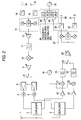
- Fig. 1 shows the configuration of a multiple-band mobile transceiver according to a first embodiment of the invention. This mobile transceiver operates for two mobile communications systems A and B using different radio frequency bands A and B.
- Reference numeral 1 denotes an antenna; 2 and 3, duplexers corresponding to two respective radio frequency bands; 4 and 5, isolators corresponding to two respective transmission frequency bands; 6 and 7, power amplifiers corresponding to the respective transmission frequency bands; 8, a high-frequency switch; 9, a variable gain amplifier; 10, a transmission mixer; 11, a lowpass filter; 12, a variable gain amplifier; 13, a quadrature modulator; 14 and 15, lowpass filters for I and Q modulation input signals; 16 and 17, I and Q modulation input terminals; and 18, a first local oscillator.
- reference numerals 19 and 20 denote low-noise amplifiers corresponding to two respective reception frequency bands; 21 and 22, reception mixers corresponding to the respective reception frequency bands; 23 and 24, intermediate frequency filters corresponding to two respective reception intermediate frequencies; 25, an intermediate frequency switch; 26, a variable gain amplifier; 27, a quadrature demodulator; 28 and 29, lowpass filters for I and Q demodulation outputs; and 30 and 31, I and Q demodulation output terminals.
- Reference numeral 32 denotes a voltage-controlled oscillator
- numeral 33 denotes a frequency division and distribution section which splits an output of the voltage-controlled oscillator 32 into a transmission modulation local oscillation signal and a reception second local oscillation signal while frequency-dividing the output of the voltage-controlled oscillator 32.
- the frequency division and distribution section 33 consists of frequency dividers 41, 42, 44, and 45, and switches 43 and 46.
- the voltage-controlled oscillator 32 and the frequency division and distribution section 33 constitute a frequency synthesizer.
- Signals that are input from the I and Q modulation input terminals 16 and 17 are modulated by the quadrature modulator 13, and then up-converted into a radio frequency by the transmission mixer 10.
- a resulting signal is subjected to a gain adjustment by the variable gain amplifier 9, and then input to the power amplifier 6 or 7 by the high-frequency switch 8 for the transmission frequency band concerned.
- An output of the power amplifier 6 or 7 is passed through the isolator 4 or 5, and then input to the duplexer 2 or 3 corresponding to the radio frequency band concerned.
- the signal is transmitted from an antenna 1 to a radio base station as radio waves.
- a signal transmitted from a radio base station is separated from transmission waves of the mobile transceiver by the duplexer 2 or 3 corresponding to the radio frequency band concerned, amplified by the low-noise amplifier 19 or 20 corresponding to the reception frequency band concerned, and then converted into a signal of the reception intermediate frequency concerned by the reception mixer 21 or 22.
- An output of the reception mixer 21 or 22 is passed through the intermediate frequency filter 23 or 24 corresponding to the reception intermediate frequency concerned, and then selected by the intermediate frequency switch 25.
- An output of the intermediate frequency switch 25 is subjected to a gain adjustment by the variable gain amplifier 26, and then converted into I and Q demodulation signals by the quadrature demodulator 27.
- the switch 43 selects the divider 41 when the mobile transceiver is operating for the mobile communications system A, and selects the divider 42 when it is operating for the mobile communications system B. Frequency division numbers corresponding to the mobile communications systems A and B are set in the dividers 41 and 42, respectively.
- the switch 46 which is a 2-input/2-output composite switch, operates such that input terminals 1a and 2a are connected to output terminals 2b and 1b, respectively when the mobile transceiver is operating for the mobile communications system A, and that input terminals 1a and 2a are connected to output terminals 1b and 2b, respectively when the mobile transceiver is operating for the mobile communications system B.
- the frequency division number of each of the dividers 44 and 45 is so set as to correspond to a transmission modulation local oscillation signal or a reception second oscillation signal.
- the path of the divider 44 is selected for a second local oscillation signal and the path of the divider 45 is selected for a transmission modulation local oscillation signal.
- the path of the divider 44 is selected for a transmission modulation oscillation signal and the path of the divider 45 is selected for a reception second local oscillation signal.
- the frequency division numbers set in the dividers 44 and 45 are fixed.
- an output of the voltage-controlled oscillator 32 is frequency-divided by the divider 41 or 42, and then split and supplied to the dividers 44 and 45.
- the composite switch 46 selects and outputs a transmission modulation local oscillation signal and a reception second local oscillation signal.
- Table 1 summarizes the frequency division numbers in the frequency division and distribution section 33 to produce a transmission modulation oscillation signal and a reception second local oscillation signal for each of the mobile communications systems A and B.
- Table 1 Mobile communications systems Transmission modulation local oscillation signal Reception second local oscillation signal A (Division number of divider 41) x (division number of divider 45) (Division number of divider 41) x (division number of divider 44) B (Division number of divider 42) x (division number of divider 44) (Division number of divider 42) x (division number of divider 45)
- the single frequency synthesizer can accommodate any combination of the mobile communications systems A and B and the above local oscillation signals if the frequency division numbers of the dividers 41, 42, 44, and 45 and the oscillation frequencies of the voltage-controlled oscillator 32 are properly set in accordance with the radio frequency bands used by the mobile communications system A and B.
- Table 2 shows an example of a relationship among a central frequency f L1 of the first local oscillator 18, a reception intermediate frequency f IF (reception second local oscillation frequency f L2 ), a transmission modulation local oscillation frequency f mod , and an oscillation frequency f vco of the voltage-controlled oscillator 32 for each of the mobile communications systems A and B.
- Table 2 Mobile communications system f L1 f IF (f L2 ) f mod f vco A 1,690 MHz 240 MHz 160 MHz 960 MHz B 970 MHz 90 MHz 135 MHz 1,080 MHz
- the frequencies of a transmission modulation local oscillation signal and a reception second local oscillation signal as outputs of the frequency division and distribution section 33 are twice the frequencies f mod and f L2 , respectively. This is because a 1/2 frequency divider is provided in each of the quadrature modulator 13 and the quadrature demodulator 27. If I and Q signals are baseband-detected by the quadrature demodulator 27, the reception intermediate frequency f IF and the reception second local oscillation frequency f L2 are identical.
- the frequency relationship of Table 2 is just an example. Where the frequency division numbers of the respective dividers are set as shown in Table 3, it suffices that the reception intermediate frequency f IF and the transmission modulation local oscillation frequency f mod for the mobile communications system A have a ratio 3:2, and that the reception intermediate frequency f IF and the transmission modulation local oscillation frequency f mod for the mobile communications system B have a ratio 2:3.
- the degree of freedom of frequency selection is sufficiently high to satisfy such requirements.
- the voltage-controlled oscillator 32 Since the oscillation frequencies of the voltage-controlled oscillator 32 corresponding to the mobile communications systems A and B are 960 MHz and 1,080 MHz, respectively, it suffices that the voltage-controlled oscillator 32 have a frequency variable range of about 150 MHz. Even in a case where the voltage-controlled oscillator 32 operates at 3 V, the sensitivity of a variable capacitance diode may be set at about 50 MHz/V; it is possible to implement such a circuit configuration. Where the voltage-controlled oscillator 32 operates a 5 V, the sensitivity of the variable capacitance diode may be set at about 30 MHz/V. However, where the voltage range of the voltage-controlled oscillator 32 is required to be lower than 3 V, it may be necessary to provide, for instance, a means for switching the capacitance of a resonance circuit.
- the dividers 41, 42, 44, and 45 are separate elements having fixed frequency division numbers.
- This configuration may be modified such that the dividers 41 and 42 are implemented by a single element whose frequency division number is switched in accordance with the mobile communications system for which the mobile transceiver is operating, and/or that the dividers 44 and 45 are implemented by a single element whose frequency division number is switched in a time-divisional manner. Because most of TDMA mobile communications systems allocate different time slots to transmission and reception, a single divider may be provided which is switched in a time-divisional manner for transmission and reception. As a further alternative, even a single element whose frequency division number is switched in a time-divisional manner may be provided instead of the dividers 41, 42, 44, and 45, with the switch 43 omitted.
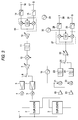
- Fig. 2 shows the configuration of a multiple-band mobile transceiver according to a second embodiment of the invention. Also in this embodiment, the mobile transceiver operates for two mobile communications systems A and B using different radio frequency bands A and B.
- Fig. 2 other than a frequency division and distribution section 36 is the same as that of Fig. 1.
- a voltage-controlled oscillator 32 and the frequency division and distribution section 36 constitute a frequency synthesizer.
- the frequency division and distribution section 36 consists of frequency dividers 51-54 which have frequency division numbers accommodating all the combinations (4 kinds) of the mobile communications systems A and B and the transmission modulation local oscillation signal/reception second local oscillation signal, and switches 55 and 56 that are switched in accordance with the mobile communications system for which the mobile transceiver is operating.
- a frequency division number corresponding to the mobile communications system A and the transmission modulation local oscillation signal is set in the divider 51.
- a frequency division number corresponding to the mobile communications system B and the transmission modulation local oscillation signal is set in the divider 52.
- a frequency division number corresponding to the mobile communications system A and the reception second local oscillation signal is set in the divider 53.
- a frequency division number corresponding to the mobile communications system B and the reception second local oscillation signal is set in the divider 54.
- the switch 55 selects the divider 51 when the mobile transceiver is operating for the mobile communications system A, and selects the divider 52 when the mobile transceiver is operating for the mobile communications system B.
- the switch 56 selects the divider 53 when the mobile transceiver is operating for the mobile communications system A, and selects the divider 54 when the mobile transceiver is operating for the mobile communications system B.
- An output signal of the voltage-controlled oscillator 32 is split and supplied to the dividers 51-54.
- the number of dividers is equal to the number of all the combinations (4 kinds) of the mobile communications systems (two) and the transmission modulation local oscillation signal/reception second local oscillation signal.
- the switches 55 and 56 select the path of the divider 51 for the transmission modulation local oscillation signal and select the path of the divider 53 for the reception second local oscillation signal.
- the switches 55 and 56 select the path of the divider 52 for the transmission modulation local oscillation signal and select the path of the divider 54 for the reception second local oscillation signal.
- the example of the frequency relationship mentioned in the first embodiment is satisfied by setting the frequency division numbers of the dividers 51-54 as shown in Table 4.
- Table 4 Divider 51 Divider 52 Divider 53 Divider 54 Division number 1/3 1/4 1/2 1/6
- an output of the frequency division and distribution section is split into a transmission modulation local oscillation signal and a reception second local oscillation signal while being frequency-divided at proper dividing ratios, whereby a single frequency synthesizer can provide both of the transmission modulation local oscillation signal and the reception second local oscillation signal for each mobile communications system.
Landscapes
- Engineering & Computer Science (AREA)
- Computer Networks & Wireless Communication (AREA)
- Signal Processing (AREA)
- Power Engineering (AREA)
- Transceivers (AREA)
- Transmitters (AREA)
- Mobile Radio Communication Systems (AREA)
- Superheterodyne Receivers (AREA)
Applications Claiming Priority (3)
| Application Number | Priority Date | Filing Date | Title |
|---|---|---|---|
| JP66056/96 | 1996-03-22 | ||
| JP6605696 | 1996-03-22 | ||
| JP8066056A JPH09261106A (ja) | 1996-03-22 | 1996-03-22 | 複数帯域移動無線機 |
Publications (2)
| Publication Number | Publication Date |
|---|---|
| EP0797311A2 true EP0797311A2 (fr) | 1997-09-24 |
| EP0797311A3 EP0797311A3 (fr) | 2003-02-05 |
Family
ID=13304839
Family Applications (1)
| Application Number | Title | Priority Date | Filing Date |
|---|---|---|---|
| EP97102107A Withdrawn EP0797311A3 (fr) | 1996-03-22 | 1997-02-10 | Radio émetteur-récepteur mobile et à multibande avec un nombre réduit d'oscillateurs locaux |
Country Status (4)
| Country | Link |
|---|---|
| US (1) | US5966666A (fr) |
| EP (1) | EP0797311A3 (fr) |
| JP (1) | JPH09261106A (fr) |
| CN (1) | CN1093706C (fr) |
Cited By (7)
| Publication number | Priority date | Publication date | Assignee | Title |
|---|---|---|---|---|
| EP0905917A2 (fr) * | 1997-09-26 | 1999-03-31 | Matsushita Electric Industrial Co., Ltd. | Système de communication sans fil multimode |
| KR20010001804A (ko) * | 1999-06-08 | 2001-01-05 | 윤종용 | 휴대용 무선 단말기의 송·수신장치 |
| EP1193868A2 (fr) * | 2000-09-28 | 2002-04-03 | Kabushiki Kaisha Toshiba | Dispositif amplificateur à gain variable |
| EP1492243A2 (fr) * | 2003-06-24 | 2004-12-29 | Matsushita Electric Industrial Co., Ltd. | Dispositif de réception haute fréquence ainsi que circuit intégré utilisé à cette fin, et récepteur de télévision utilisant les deux |
| EP1494350A3 (fr) * | 2003-07-03 | 2006-04-26 | Matsushita Electric Industrial Co., Ltd. | Amplificateur haute fréquence et terminal mobile de communication |
| CN100397793C (zh) * | 2003-10-14 | 2008-06-25 | 松下电器产业株式会社 | 高频接收装置和它所使用的集成电路 |
| US8768408B2 (en) | 1998-11-26 | 2014-07-01 | Nokia Corporation | Method and arrangement for transmitting and receiving RF signals through various radio interfaces of communication systems |
Families Citing this family (49)
| Publication number | Priority date | Publication date | Assignee | Title |
|---|---|---|---|---|
| JP3088338B2 (ja) * | 1997-05-28 | 2000-09-18 | 埼玉日本電気株式会社 | 無線電話装置 |
| JP3825540B2 (ja) * | 1997-09-05 | 2006-09-27 | 松下電器産業株式会社 | 受信機および送受信機 |
| WO1999025076A1 (fr) * | 1997-11-06 | 1999-05-20 | Koninklijke Philips Electronics N.V. | Emetteur-recepteur et systeme de telecommunications faisant appel a ce dernier |
| US20030003887A1 (en) * | 1998-05-29 | 2003-01-02 | Lysander Lim | Radio-frequency communication apparatus and associated methods |
| US6993314B2 (en) * | 1998-05-29 | 2006-01-31 | Silicon Laboratories Inc. | Apparatus for generating multiple radio frequencies in communication circuitry and associated methods |
| US6175724B1 (en) * | 1998-07-31 | 2001-01-16 | Motorola, Inc. | Band switchable injection oscillator and communication device using same |
| US6484014B1 (en) * | 1999-03-22 | 2002-11-19 | Ericsson Inc. | Reduced component frequency plan architecture for dual band transceiver |
| US6115584A (en) * | 1999-04-02 | 2000-09-05 | Trw Inc. | Transmitter-receiver for use in broadband wireless access communications systems |
| US6584090B1 (en) * | 1999-04-23 | 2003-06-24 | Skyworks Solutions, Inc. | System and process for shared functional block CDMA and GSM communication transceivers |
| FI112561B (fi) * | 1999-06-10 | 2003-12-15 | Nokia Corp | Lähetin/vastaanotin RF-signaalin lähettämiseksi ja vastaanottamiseksi ainakin kahdella taajuusalueella |
| JP4547084B2 (ja) * | 1999-11-15 | 2010-09-22 | ルネサスエレクトロニクス株式会社 | 移動体通信機および送受信機 |
| US6826388B1 (en) | 1999-11-15 | 2004-11-30 | Renesas Technology Corp. | Mobile communication apparatus including dividers in transmitter and receiver |
| US7027792B1 (en) | 1999-11-23 | 2006-04-11 | Micro Linear Corporation | Topology for a single ended input dual balanced mixer |
| US6987816B1 (en) | 1999-11-23 | 2006-01-17 | Micro Linear Corporation | Iris data recovery algorithms |
| US6985541B1 (en) | 1999-11-23 | 2006-01-10 | Micor Linear Corporation | FM demodulator for a low IF receiver |
| US7076217B1 (en) * | 1999-11-23 | 2006-07-11 | Micro Linear Corporation | Integrated radio transceiver |
| US6912376B1 (en) * | 1999-12-27 | 2005-06-28 | Texas Instruments Incorporated | Mobile phone transceiver |
| KR100690954B1 (ko) * | 2000-01-19 | 2007-03-09 | 코닌클리케 필립스 일렉트로닉스 엔.브이. | 무선 fm 수신기 |
| JP2002009638A (ja) * | 2000-06-19 | 2002-01-11 | Nec Corp | 通信装置の電力増幅回路 |
| WO2002011470A1 (fr) * | 2000-08-02 | 2002-02-07 | Conexant Systems, Inc. | Emetteur/recepteur de communication, a bloc commun et a capacite gps |
| JP4524889B2 (ja) * | 2000-09-05 | 2010-08-18 | パナソニック株式会社 | 通信装置 |
| KR100473131B1 (ko) * | 2001-02-21 | 2005-03-10 | 아사히 가세이 마이크로시스템 가부시끼가이샤 | 통신 장치 |
| GB2382242B (en) * | 2001-11-15 | 2005-08-03 | Hitachi Ltd | Direct-conversion transmitting circuit and integrated transmitting/receiving circuit |
| US6728517B2 (en) * | 2002-04-22 | 2004-04-27 | Cognio, Inc. | Multiple-input multiple-output radio transceiver |
| AU2003228602A1 (en) * | 2002-04-22 | 2003-11-03 | Cognio, Inc. | Multiple-input multiple-output radio transceiver |
| JP3908591B2 (ja) | 2002-05-01 | 2007-04-25 | ソニー・エリクソン・モバイルコミュニケーションズ株式会社 | 変復調装置および携帯無線機 |
| JP2004088372A (ja) * | 2002-08-27 | 2004-03-18 | Renesas Technology Corp | 受信機及びそれを用いた無線通信端末機器 |
| KR100472484B1 (ko) * | 2002-12-10 | 2005-03-10 | 삼성전자주식회사 | 무선 신호 병렬 처리 장치 및 그 방법 |
| WO2004057768A1 (fr) * | 2002-12-20 | 2004-07-08 | Renesas Technology Corp. | Circuit de transmission et emetteur/recepteur utilisant ledit circuit |
| JP4246166B2 (ja) | 2004-03-04 | 2009-04-02 | パナソニック株式会社 | 分周回路及びそれを用いたマルチモード無線機 |
| JP4327666B2 (ja) * | 2004-06-23 | 2009-09-09 | 株式会社ルネサステクノロジ | 無線送信回路及びそれを用いた送受信機 |
| US7395040B2 (en) * | 2005-03-29 | 2008-07-01 | Broadcom Corporation | Multiple band multiple input multiple output transceiver integrated circuit |
| US7787843B2 (en) * | 2005-03-29 | 2010-08-31 | Broadcom Corporation | Multiple band direct conversion radio frequency transceiver integrated circuit |
| US7616929B2 (en) * | 2005-04-04 | 2009-11-10 | Broadcom Corporation | Cross-core calibration in a multi-radio system |
| US7392026B2 (en) * | 2005-04-04 | 2008-06-24 | Freescale Semiconductor, Inc. | Multi-band mixer and quadrature signal generator for a multi-mode radio receiver |
| US7356325B2 (en) * | 2005-04-04 | 2008-04-08 | Broadcom Corporation | Local oscillation routing plan applicable to a multiple RF band RF MIMO transceiver |
| US7319849B2 (en) | 2005-08-25 | 2008-01-15 | Microtune (Texas), L.P. | Radio-frequency tuner with differential converter |
| US7502278B1 (en) * | 2006-05-23 | 2009-03-10 | Maxim Integrated Products, Inc. | Analog beamformers for continuous wave ultrasonic receivers |
| US8599938B2 (en) * | 2007-09-14 | 2013-12-03 | Qualcomm Incorporated | Linear and polar dual mode transmitter circuit |
| US8019310B2 (en) * | 2007-10-30 | 2011-09-13 | Qualcomm Incorporated | Local oscillator buffer and mixer having adjustable size |
| US8929840B2 (en) * | 2007-09-14 | 2015-01-06 | Qualcomm Incorporated | Local oscillator buffer and mixer having adjustable size |
| US7941115B2 (en) * | 2007-09-14 | 2011-05-10 | Qualcomm Incorporated | Mixer with high output power accuracy and low local oscillator leakage |
| JP4840323B2 (ja) * | 2007-10-05 | 2011-12-21 | 株式会社デンソー | 衛星測位用受信装置 |
| US8639205B2 (en) * | 2008-03-20 | 2014-01-28 | Qualcomm Incorporated | Reduced power-consumption receivers |
| KR101501153B1 (ko) * | 2009-02-13 | 2015-03-16 | 삼성전자주식회사 | 무선통신시스템에서 주파수 재배치를 지원하기 위한 장치 및 방법 |
| US8744380B2 (en) * | 2011-03-17 | 2014-06-03 | Harris Corporation | Unified frequency synthesizer for direct conversion receiver or transmitter |
| CN102752010B (zh) * | 2011-04-21 | 2016-06-15 | 沈阳中科微电子有限公司 | 一种用于通信基站的收发模块 |
| CN104135301B (zh) | 2014-08-07 | 2017-01-11 | 华为技术有限公司 | 一种射频接收机及接收方法 |
| US11086002B1 (en) * | 2015-04-21 | 2021-08-10 | Maxim Integrated Products, Inc. | Ultrasound sub-array receiver beamformer |
Family Cites Families (10)
| Publication number | Priority date | Publication date | Assignee | Title |
|---|---|---|---|---|
| EP0484158B1 (fr) * | 1990-10-31 | 1996-04-17 | Nec Corporation | Radio émetteur-récepteur avec synthétiseur à boucle à verrouillage de phase |
| JP2850160B2 (ja) * | 1991-01-25 | 1999-01-27 | 松下電器産業株式会社 | 時分割複信無線送受信装置 |
| JP3358183B2 (ja) * | 1993-04-09 | 2002-12-16 | ソニー株式会社 | 時分割多重送受信装置 |
| FR2707063B1 (fr) * | 1993-06-25 | 1995-09-22 | Alcatel Mobile Comm France | |
| US5422931A (en) * | 1993-09-22 | 1995-06-06 | Hughes Aircraft Company | Dual mode portable cellular telephone having switch control of the rf signal path to effectuate power savings |
| FI941862A (fi) * | 1994-04-21 | 1995-10-22 | Nokia Mobile Phones Ltd | Menetelmä ja radiotaajuusjärjestelmä kahden eri taajuusalueella toimivan radioviestinjärjestelmän vastaanottimen ja lähettimen taajuuksien muodostamiseksi ja kahdella eri taajuusalueella toimiva vastaanotin ja lähetin sekä edellisten käyttö matkapuhelimessa |
| US5519887A (en) * | 1994-08-09 | 1996-05-21 | At&T Corp. | Switchable filter phase-locked loop frequency synthesizer device and method for achieving dual-mode cellular communications |
| JPH08265211A (ja) * | 1995-03-22 | 1996-10-11 | Sony Corp | 集積回路および送受信機 |
| JP3070442B2 (ja) * | 1995-05-24 | 2000-07-31 | 日本電気株式会社 | ディジタル変復調回路 |
| US5732330A (en) * | 1996-07-02 | 1998-03-24 | Ericsson Inc. | Dual band transceiver |
-
1996
- 1996-03-22 JP JP8066056A patent/JPH09261106A/ja active Pending
-
1997
- 1997-02-06 US US08/796,906 patent/US5966666A/en not_active Expired - Lifetime
- 1997-02-10 EP EP97102107A patent/EP0797311A3/fr not_active Withdrawn
- 1997-03-21 CN CN97103347A patent/CN1093706C/zh not_active Expired - Fee Related
Non-Patent Citations (1)
| Title |
|---|
| None |
Cited By (19)
| Publication number | Priority date | Publication date | Assignee | Title |
|---|---|---|---|---|
| EP0905917A2 (fr) * | 1997-09-26 | 1999-03-31 | Matsushita Electric Industrial Co., Ltd. | Système de communication sans fil multimode |
| EP0905917A3 (fr) * | 1997-09-26 | 2003-09-17 | Matsushita Electric Industrial Co., Ltd. | Système de communication sans fil multimode |
| US9270301B2 (en) | 1998-11-26 | 2016-02-23 | Nokia Technologies Oy | Method and arrangement for transmitting and receiving RF signals through various radio interfaces of communication systems |
| US8838049B1 (en) | 1998-11-26 | 2014-09-16 | Nokia Corporation | Method and arrangement for transmitting and receiving RF signals through various radio interfaces of communication systems |
| US8768408B2 (en) | 1998-11-26 | 2014-07-01 | Nokia Corporation | Method and arrangement for transmitting and receiving RF signals through various radio interfaces of communication systems |
| KR20010001804A (ko) * | 1999-06-08 | 2001-01-05 | 윤종용 | 휴대용 무선 단말기의 송·수신장치 |
| EP1193868A2 (fr) * | 2000-09-28 | 2002-04-03 | Kabushiki Kaisha Toshiba | Dispositif amplificateur à gain variable |
| EP1193868A3 (fr) * | 2000-09-28 | 2004-01-07 | Kabushiki Kaisha Toshiba | Dispositif amplificateur à gain variable |
| US7031684B2 (en) | 2000-09-28 | 2006-04-18 | Kabushiki Kaisha Toshiba | Variable gain amplifier device |
| US7065334B1 (en) | 2000-09-28 | 2006-06-20 | Kabushiki Kaisha Toshiba | Variable gain amplifier device |
| CN100379157C (zh) * | 2003-06-24 | 2008-04-02 | 松下电器产业株式会社 | 高频接收装置、其使用的集成电路和电视接收机 |
| US7184733B2 (en) | 2003-06-24 | 2007-02-27 | Matsushita Electric Industrial Co., Ltd. | High frequency receiving device, integrated circuit used for the same, and TV receiver using them |
| EP1492243A3 (fr) * | 2003-06-24 | 2005-03-16 | Matsushita Electric Industrial Co., Ltd. | Dispositif de réception haute fréquence ainsi que circuit intégré utilisé à cette fin, et récepteur de télévision utilisant les deux |
| EP1492243A2 (fr) * | 2003-06-24 | 2004-12-29 | Matsushita Electric Industrial Co., Ltd. | Dispositif de réception haute fréquence ainsi que circuit intégré utilisé à cette fin, et récepteur de télévision utilisant les deux |
| US7239205B2 (en) | 2003-07-03 | 2007-07-03 | Matsushita Electric Industrial Co., Ltd. | High frequency amplifier circuit and mobile communication terminal using the same |
| US7626459B2 (en) | 2003-07-03 | 2009-12-01 | Panasonic Corporation | High frequency amplifier circuit and mobile communication terminal using the same |
| US7924098B2 (en) | 2003-07-03 | 2011-04-12 | Panasonic Corporation | High frequency amplifier circuit and mobile communication terminal using the same |
| EP1494350A3 (fr) * | 2003-07-03 | 2006-04-26 | Matsushita Electric Industrial Co., Ltd. | Amplificateur haute fréquence et terminal mobile de communication |
| CN100397793C (zh) * | 2003-10-14 | 2008-06-25 | 松下电器产业株式会社 | 高频接收装置和它所使用的集成电路 |
Also Published As
| Publication number | Publication date |
|---|---|
| US5966666A (en) | 1999-10-12 |
| CN1093706C (zh) | 2002-10-30 |
| JPH09261106A (ja) | 1997-10-03 |
| CN1166730A (zh) | 1997-12-03 |
| EP0797311A3 (fr) | 2003-02-05 |
Similar Documents
| Publication | Publication Date | Title |
|---|---|---|
| US5966666A (en) | Multiple-band mobile transceiver having a smaller number of local oscillators | |
| EP0581573B1 (fr) | Radiotéléphone universel | |
| US6766178B1 (en) | RF architecture for cellular multi-band telephones | |
| EP1184970B1 (fr) | Synthétiseur de fréquences et dispositif de radio à plusieurs bandes utilisant ledit synthétiseur | |
| US5852784A (en) | Multiband mobile unit communication apparatus | |
| KR100224102B1 (ko) | 이중 대역 셀룰러 전화에 이용되는 중간주파수 선택장치 및 방법 | |
| EP0798880B1 (fr) | Méthode pour la génération des fréquences dans un émetteur-récepteur à conversion directe d'un système de radiocommunication à bande duale, un émetteur-récepteur à conversion directe d'un système de radiocommunication à bande duale, et la mise en action de cette méthode et cet appareil dans une station mobile | |
| EP0905917B1 (fr) | Système de communication sans fil multimode | |
| US7327993B2 (en) | Low leakage local oscillator system | |
| KR20010015530A (ko) | 다중 모드 직접 변환 수신기 | |
| GB2310342A (en) | Dual mode radio transceiver front end | |
| EP1133831A1 (fr) | Procede et schema destines a l'emission et a la reception de signaux hf a travers diverses interfaces radio de systemes de communication | |
| JPH04240924A (ja) | 時分割複信無線送受信装置 | |
| FI109736B (fi) | Vastaanottimen taajuusalueen ja kaistanleveyden vaihto peilitaajuutta vaimentavan sekoittimen avulla | |
| KR100458715B1 (ko) | 통신 시스템 장치 | |
| WO1998052292A1 (fr) | Recepteur radio a deux bandes | |
| KR20000070694A (ko) | 통신 시스템과, 통신 장치, 및 주파수 신시사이저 | |
| CN100492881C (zh) | 本地振荡器电路以及包括该电路的无线装置和通信系统 | |
| US7471934B2 (en) | Transmitter method, apparatus, and frequency plan for minimizing spurious energy | |
| US6628960B1 (en) | Multi-mode radio receiver | |
| KR20000069896A (ko) | 트랜시버 및 트랜시버를 구비하는 통신 시스템 | |
| JP2002280924A (ja) | マルチバンド送受信装置 | |
| KR20000068744A (ko) | 다중 채널 무선 장치, 무선 통신 시스템, 및 분수 분할 주파수신시사이저 | |
| EP0548885A2 (fr) | Transmetteur-récepteur TDMA-TDD | |
| US6486732B2 (en) | Modulator-demodulator |
Legal Events
| Date | Code | Title | Description |
|---|---|---|---|
| PUAI | Public reference made under article 153(3) epc to a published international application that has entered the european phase |
Free format text: ORIGINAL CODE: 0009012 |
|
| AK | Designated contracting states |
Kind code of ref document: A2 Designated state(s): DE GB SE |
|
| PUAL | Search report despatched |
Free format text: ORIGINAL CODE: 0009013 |
|
| AK | Designated contracting states |
Designated state(s): DE GB SE |
|
| 17P | Request for examination filed |
Effective date: 20030805 |
|
| 17Q | First examination report despatched |
Effective date: 20040714 |
|
| GRAP | Despatch of communication of intention to grant a patent |
Free format text: ORIGINAL CODE: EPIDOSNIGR1 |
|
| STAA | Information on the status of an ep patent application or granted ep patent |
Free format text: STATUS: THE APPLICATION IS DEEMED TO BE WITHDRAWN |
|
| 18D | Application deemed to be withdrawn |
Effective date: 20060406 |