EP0796982B1 - Engine valve control system using a latchable rocker arm activated by a solenoid mechanism - Google Patents
Engine valve control system using a latchable rocker arm activated by a solenoid mechanism Download PDFInfo
- Publication number
- EP0796982B1 EP0796982B1 EP97301308A EP97301308A EP0796982B1 EP 0796982 B1 EP0796982 B1 EP 0796982B1 EP 97301308 A EP97301308 A EP 97301308A EP 97301308 A EP97301308 A EP 97301308A EP 0796982 B1 EP0796982 B1 EP 0796982B1
- Authority
- EP
- European Patent Office
- Prior art keywords
- rocker arm
- arm
- spring
- control system
- plunger
- Prior art date
- Legal status (The legal status is an assumption and is not a legal conclusion. Google has not performed a legal analysis and makes no representation as to the accuracy of the status listed.)
- Expired - Lifetime
Links
- 230000007246 mechanism Effects 0.000 title description 20
- 230000004044 response Effects 0.000 claims description 10
- 230000006835 compression Effects 0.000 claims description 9
- 238000007906 compression Methods 0.000 claims description 9
- 238000002485 combustion reaction Methods 0.000 claims description 5
- 238000006073 displacement reaction Methods 0.000 claims description 4
- 230000036316 preload Effects 0.000 description 15
- 230000006870 function Effects 0.000 description 5
- 230000036961 partial effect Effects 0.000 description 4
- 238000000926 separation method Methods 0.000 description 3
- 230000009471 action Effects 0.000 description 2
- 230000004913 activation Effects 0.000 description 2
- 230000000670 limiting effect Effects 0.000 description 2
- 230000004048 modification Effects 0.000 description 2
- 238000012986 modification Methods 0.000 description 2
- 230000004075 alteration Effects 0.000 description 1
- 230000003321 amplification Effects 0.000 description 1
- 230000008901 benefit Effects 0.000 description 1
- 238000010276 construction Methods 0.000 description 1
- 230000009849 deactivation Effects 0.000 description 1
- 230000009977 dual effect Effects 0.000 description 1
- 230000005672 electromagnetic field Effects 0.000 description 1
- 238000003199 nucleic acid amplification method Methods 0.000 description 1
- 238000004806 packaging method and process Methods 0.000 description 1
- 230000001737 promoting effect Effects 0.000 description 1
- 230000002829 reductive effect Effects 0.000 description 1
- 230000000717 retained effect Effects 0.000 description 1
- 230000003068 static effect Effects 0.000 description 1
Images


Classifications
-
- F—MECHANICAL ENGINEERING; LIGHTING; HEATING; WEAPONS; BLASTING
- F01—MACHINES OR ENGINES IN GENERAL; ENGINE PLANTS IN GENERAL; STEAM ENGINES
- F01L—CYCLICALLY OPERATING VALVES FOR MACHINES OR ENGINES
- F01L13/00—Modifications of valve-gear to facilitate reversing, braking, starting, changing compression ratio, or other specific operations
- F01L13/0005—Deactivating valves
-
- F—MECHANICAL ENGINEERING; LIGHTING; HEATING; WEAPONS; BLASTING
- F01—MACHINES OR ENGINES IN GENERAL; ENGINE PLANTS IN GENERAL; STEAM ENGINES
- F01L—CYCLICALLY OPERATING VALVES FOR MACHINES OR ENGINES
- F01L1/00—Valve-gear or valve arrangements, e.g. lift-valve gear
- F01L1/12—Transmitting gear between valve drive and valve
- F01L1/18—Rocking arms or levers
- F01L1/185—Overhead end-pivot rocking arms
-
- F—MECHANICAL ENGINEERING; LIGHTING; HEATING; WEAPONS; BLASTING
- F01—MACHINES OR ENGINES IN GENERAL; ENGINE PLANTS IN GENERAL; STEAM ENGINES
- F01L—CYCLICALLY OPERATING VALVES FOR MACHINES OR ENGINES
- F01L1/00—Valve-gear or valve arrangements, e.g. lift-valve gear
- F01L1/20—Adjusting or compensating clearance
- F01L1/22—Adjusting or compensating clearance automatically, e.g. mechanically
- F01L1/24—Adjusting or compensating clearance automatically, e.g. mechanically by fluid means, e.g. hydraulically
- F01L1/2405—Adjusting or compensating clearance automatically, e.g. mechanically by fluid means, e.g. hydraulically by means of a hydraulic adjusting device located between the cylinder head and rocker arm
-
- F—MECHANICAL ENGINEERING; LIGHTING; HEATING; WEAPONS; BLASTING
- F01—MACHINES OR ENGINES IN GENERAL; ENGINE PLANTS IN GENERAL; STEAM ENGINES
- F01L—CYCLICALLY OPERATING VALVES FOR MACHINES OR ENGINES
- F01L1/00—Valve-gear or valve arrangements, e.g. lift-valve gear
- F01L1/12—Transmitting gear between valve drive and valve
- F01L1/18—Rocking arms or levers
- F01L2001/186—Split rocking arms, e.g. rocker arms having two articulated parts and means for varying the relative position of these parts or for selectively connecting the parts to move in unison
-
- F—MECHANICAL ENGINEERING; LIGHTING; HEATING; WEAPONS; BLASTING
- F01—MACHINES OR ENGINES IN GENERAL; ENGINE PLANTS IN GENERAL; STEAM ENGINES
- F01L—CYCLICALLY OPERATING VALVES FOR MACHINES OR ENGINES
- F01L13/00—Modifications of valve-gear to facilitate reversing, braking, starting, changing compression ratio, or other specific operations
- F01L2013/10—Auxiliary actuators for variable valve timing
- F01L2013/101—Electromagnets
-
- F—MECHANICAL ENGINEERING; LIGHTING; HEATING; WEAPONS; BLASTING
- F01—MACHINES OR ENGINES IN GENERAL; ENGINE PLANTS IN GENERAL; STEAM ENGINES
- F01L—CYCLICALLY OPERATING VALVES FOR MACHINES OR ENGINES
- F01L2305/00—Valve arrangements comprising rollers
-
- F—MECHANICAL ENGINEERING; LIGHTING; HEATING; WEAPONS; BLASTING
- F01—MACHINES OR ENGINES IN GENERAL; ENGINE PLANTS IN GENERAL; STEAM ENGINES
- F01L—CYCLICALLY OPERATING VALVES FOR MACHINES OR ENGINES
- F01L2820/00—Details on specific features characterising valve gear arrangements
- F01L2820/01—Absolute values
Definitions
- the present invention relates to a valve operating apparatus for an internal combustion engine and, more specifically, to an apparatus to cause the engine valve to operate or not to operate depending on the energization state of a solenoid actuator.
- Variable valve control systems for multiple valve engines wherein the intake and/or exhaust valves can either be selectively actuated or actuated at selected lift profiles are well known in the art.
- Example systems are shown in U.S. Patent Nos. 4,151,817 and 4,203,397.
- Patent 4,151,817 discloses a primary rocker arm element engageable with a first cam profile, a secondary rocker arm element engageable with a second cam profile, and means to interconnect or latch the primary and secondary arm elements.
- Patent 4,203,397 discloses an apparatus to selectively engage or disengage an engine poppet valve so as to connect or disconnect the valve from the rest of the valve gear using a latch mechanism thereby causing the valve to operate or remain stationary.
- Latchable rocker arm mechanisms known in the prior art do not provide for a relatively low activation force when the mechanism is to be shifted from either an active state to an inactive state or visa versa.
- Solenoid actuators when used with the prior art mechanisms, provide a high force level in order to effectuate the actuation of the latchable rocker arm with some type of motion amplification mechanism such as a bellcrank. It would be desirable, especially for packaging, to provide a latchable rocker arm that requires a low level of solenoid force to effectuate a shift of an engine valve from an active to an inactive state and visa versa without the need for a synchronization system for timing with the rotation of the engine.
- a solenoid actuator and an actuator linkage for providing the actuation force required to operate an engine latchable rocker arm (thereby deactivating the engine valve) is disclosed.
- a solenoid forces a spring loaded plunger against a spring loaded pivoted actuator arm which contacts and displaces a spring loaded latch member so as to uncouple an outer rocker arm from an inner rocker arm.
- the pivoted actuator arm can only be moved into the position to deactivate the engine valve when the rocker arm is up on the camshaft lobe when the contact pad of the latch member has moved into an engageable position.
- the actuator spring which contacts the plunger of the solenoid actuator can be compressed if the actuator arm is immovable thereby limiting the force transferred to the actuator arm and allowing the plunger to contact the solenoid stator whenever the solenoid coil is energized.
- the plunger contacts the actuator arm and causes it to rotate to engage the latch member.
- an internal spring is compressed within the actuation arm.
- the latch member is unloaded and the preloaded spring acting within the actuator arm causes the pivoted actuator arm to move the latch member to a position to decouple the inner and outer rocker arms thereby deactivating operation of the engine valve.
- the spring in the actuator arm is compressed and preloads the latch member to move into an unlatched inactive position as soon as the latch member is unloaded.
- the actuator can be energized at any time without regard to the position of the engine camshaft using a relatively low power solenoid actuator.
- a bellcrank is moved into position by a solenoid actuator.
- the solenoid actuator contains a plunger which operates against a spring to allow the plunger to contact a stator whenever the solenoid coil is energized.
- the bellcrank applies a force to the latch member as the engine valve is closed thereby displacing the latch member to decouple the inner and outer rocker arms to disable the engine valve.
- One aspect of the present invention is to provide a relatively low power solenoid having a spring to couple an armature to a plunger and a linkage mechanism that requires a reduced level of actuation power to cause a latchable rocker arm to activate and deactivate an engine valve.
- Another aspect of the present invention is to provide a solenoid actuator which allows an armature to move into contact with a stator while loading a spring against a plunger.
- the actuator can be energized at any time without synchronization with the rotation of the engine.
- Another aspect of the present invention is to provide a linkage mechanism between an actuator and a latchable rocker arm where the linkage mechanism includes a pivoted telescoping actuator arm having a compression spring contained therein for contacting the latchable rocker arm.
- Another aspect of the present invention is to provide a linkage mechanism between an actuator and a latchable rocker arm where the linkage mechanism includes an actuator spring between the plunger and the solenoid armature in combination with a pivoted telescoping actuator arm.
- Another aspect of the present invention is to provide a linkage mechanism between a solenoid and a latchable rocker arm where the linkage mechanism includes a pivoted telescoping actuator arm containing an actuator spring and a return spring.
- Another aspect of the present invention is to provide a linkage mechanism between an actuator and a latchable rocker arm where the linkage mechanism includes a pivoted bellcrank contacting the solenoid plunger with one arm and contacting the latch member with a second arm.
- Another aspect of the present invention is to provide a linkage mechanism between a solenoid having an actuator spring disposed between an armature and a plunger, and a latchable rocker arm where the linkage mechanism includes a pivoted bellcrank operating against a bellcrank return spring with one arm and contacting the latch member thereby compressing a latch spring.
- Still another aspect of the present invention is to provide a linkage mechanism between a solenoid and a latchable rocker arm where the linkage mechanism includes a pivoted bellcrank contacting a solenoid plunger having a solenoid spring and a solenoid return spring with one arm and contacting the latch member of a latchable rocker arm with a second arm.
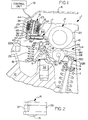
- FIG. 1 of the drawings a cross-sectional view of the engine poppet valve control system 1 of the present invention installed as part of the valve train on an internal combustion engine is shown.
- a portion of an engine cylinder head 10 of an internal combustion engine of the overhead cam type is shown along with the camshaft 4, the hydraulic lash adjuster 5, the engine poppet valve 6, the valve spring 7 and the valve cover 8.
- the engine poppet valve control system 1 is of the type which is particularly adapted to selectively activate or deactivate an engine poppet valve 6 and comprises a rocker arm assembly 14 which is shiftable between an active mode wherein it is operable to open the engine poppet valve 6, and an inactive mode wherein the valve is not opened.
- An actuator assembly 16 is operable to shift the rocker arm assembly 14 between its active and inactive modes through the movement of an actuator 16 acting through an actuator arm 17.
- the rocker arm assembly 14 comprises an inner rocker arm 18 which is engageable with the valve actuating camshaft 4 at the cam lobe 20 supported on the cylinder head 10 of the engine, an outer rocker arm 22 which is engageable with an engine poppet valve 6 which is maintained normally closed by a valve spring 7, and a biasing spring 26 acting between the inner and outer rocker arms 18 and 22 to bias the inner rocker arm 18 into engagement with the camshaft 4 through the roller follower 24 and the outer rocker arm 22 into engagement with the plunger 30 which rides in the main body 32 of lash adjuster 5.
- the construction and the function of the lash adjuster 5 are well known in the art and will not be described in detail herein.
- the biasing spring 26 applies sufficient force to the plunger 30 to keep the lash adjuster 5 operating in its normal range of operation at all times.
- a latch member 28 is slidably received on the outer rocker arm 22 and biased into a "latched" condition by latch spring 29, the latch member 28 is effective to latch the inner and outer rocker arms 18 and 22 so that they move together to define the "active mode" of the engine poppet valve control system of the present invention or to unlatch them where the inner and outer rocker arms 18 and 22 are free to rotate relative one to the other to define the "inactive mode”.
- a link pin 11 passes through coaxial apertures 61A and 61B formed in the outer rocker arm 22 (see FIG. 11) and through a link pin aperture 21 formed in the latch member 28 and provides pivotal support to the outer rocker arm 22 where the link pin 11 pivots on the plunger 30.
- the inner rocker arm 18 is pivotally supported on the link pin 11 and the outer rocker arm 22 is nonrotatably mounted on link pin 11 where the link pin 11 is supported pivotally by plunger 30 of the lash adjuster 5.
- the outer rocker arm 22 is an elongated rectangular structure having opposed side walls, and a first end 22A for engaging a biasing spring 26 and a second end 22B having a valve engagement surface 22C formed thereon.
- the valve engagement surface 22C is in contact with the engine poppet valve 6.
- the inner rocker arm 18 is an elongated rectangular structure received between the opposed side walls of the outer rocker arm 22 (see FIG. 5).
- the inner rocker arm 18 has a contact surface 18A formed thereon engageable with the latch member 28 when the rocker arm assembly 14 is in the normal active mode.
- the electromagnetic actuator assembly 16 is shown in a nonenergized state in FIG. 1 which allows the latch spring 29 to force the latch member 28 into a position to provide actuation of the engine poppet valve 5 by the camshaft 4 through the rocker arm assembly 14 in the active mode.
- Any type of suitable actuator could be utilized to provide a linear motion such as a hydraulic piston or vacuum powered piston or a rotary motor using a cam mechanism.
- the actuator assembly 16 consists of a circular armature 35 which is electromagnetically attracted toward the stator 27 when an electrical current is supplied to the coil 23 by the control unit 51.
- the plunger 45 is slidingly attached to the armature 35 and is biased along with the armature 35 away from the stator 27 by a solenoid spring 44 loaded in compression.
- the solenoid spring 44 pilots on the plunger 45 and is retained in a static position at one end against the armature 35 and at a second end by collar 47 which is secured to the plunger 45.
- the solenoid spring 44 effectively limits the amount of force that is transferred from the armature 35 to the plunger 45 by the spring rate of the solenoid spring 44 multiplied by the relative displacement between the armature 35 and the plunger 45 plus the preload force on the solenoid spring 44.
- a solenoid spring 44 having a spring rate of 1.0 Newtons/millimeter and a preload of 5.0 Newtons, a maximum force of 7.0 Newtons could be generated against the plunger 45 assuming a maximum solenoid armature travel of 2.0mm.
- the present invention provides for the generation of a highly repeatable action of the plunger 45 irrespective of changes in coil resistance due to temperature and/or changes in coil voltage.
- the armature 35 can load the solenoid spring 44 which provides for lost motion between the actuator armature 35 and the plunger 45 but provides a force against the actuator arm 17.
- the armature 35 moves to contact the stator 27 and compresses the solenoid spring 44 and thereby applies a force against the plunger 45 through the collar 47. If possible, the plunger 45 contacts and forces the actuator arm 17 downward to engage the latch member 28.
- latch member 28 compresses arm spring 39 since latch member 28 is still loaded.
- the preloaded arm spring 39 forces it into a position so that the rocker arm assembly 14 is in the inactive mode.
- the latch spring 29 has one end contacting the outer rocker arm 22 and a second end which contacts the latch member 28 thereby biasing the latch member 28 leftward so as to engage the inner rocker arm 18 to activate the engine poppet valve 6. If the latch member 28 is unloaded, the actuator arm 17 overcomes the force of the latch spring 29 and moves the latch member 28 rightwardly into the inactive mode where the engine poppet valve 6 does not open and close in response to the cam lobe 20.
- the actuator arm 17 pivots on arm pin 37 and is secured to the guide housing 36 which is attached to the actuator assembly 16.
- the actuator arm 17 contacts the latch member 28 at contact pad 48 which is formed as part of the latch member 28.
- the latch member 28 is biased toward a position to activate the engine poppet valve 6 (active mode) by the latch spring 29 which acts upon the latch member 28 against the outer rocker arm 22.
- the biasing spring 26 is preloaded to maintain a load between the roller follower 24 rotating on roller pin 25 and the camshaft 4 sufficient to keep the lash adjuster 5 operating in its normal range of adjustment. Changes in the preload on the biasing spring 26 can be made by changing the position of the preload adjuster 31 (see FIG. 5) thereby altering the position of the plunger 30 in the main body 32 of the lash adjuster 5.
- FIG. 1 illustrates the valve control system 1 in an inactive position where the actuator assembly 16 has not been energized by control unit 51 and the armature 35 is not yet magnetically attracted so as to move to come in contact with the stator 27.
- the solenoid spring 44 acts against the collar 47 pushing against the plunger 45 which in turn pushes against the actuator arm 17 in response to movement of the armature 35.
- the actuator arm 17 has an inner arm spring 39 which separates an inner housing 40 from a telescoping outer housing 42 where stop pin 33 prevents total separation of the inner and outer housings 40 and 42.
- Inner housing 40 is hinged to the guide housing 36 by arm pin 37 and contacts the plunger 45 due to return spring 43 which biases the actuator arm 17 upward.
- the rocker arm assembly is in an unloaded condition where the cam lobe 20 is contacting the roller follower 24 on the base circle, then when the actuator assembly 16 is energized. If the valve 6 is closed, the actuator arm 17 contacts the latch member 28 hitting on top of the contact pad 48. When the valve 6 opens, the actuator arm 17 is pushed by the plunger 45 into the face of the contact pad 48. As the valve 6 closes, the arm spring 39 is further compressed thereby preloading the latch member 28. When the latch member 28 is unloaded when the roller follower 24 contacts the base circle of the cam lobe 20, the latch member 28 is forced rightward, thereby shifting the rocker arm assembly 14 into the inactive mode. When the actuator assembly 16 is nonenergized as shown in FIG. 1, or the latch member 28 is loaded, the latch member 28 links the inner rocker arm 18 to the outer rocker arm 22 and the engine poppet valve 6 is activated.
- the biasing spring 26 the actuator spring 44, the arm spring 39, the return spring 43 and the latch spring 29.
- All except return spring 43 are coil springs loaded in compression.
- the actuator spring 44 is loaded in compression and functions to separate the armature 35 from the stator 27 and also functions to limit the force and motion transferred to the actuator arm 17 since one end of the actuator spring contacts the armature 35 and the second end contacts the collar 47 which is attached to the plunger 45.
- the armature 35 is slidingly coupled to the plunger 45 such that the plunger 45 moves in response to the force generated by the actuator spring 44 and not directly to the displacement of the armature 35. As shown in FIG.
- the solenoid spring 44 allows the armature 35 to move to contact the stator 27 anytime that the coil 23 is energized by the control unit 51.
- the solenoid 16 can be designed to not have sufficient force to overcome the latch return spring 29 where movement of the actuator arm 17 (or bellcrank 70 in FIG. 16) will only occur when the valve 6 is open.
- the arm spring 39 is loaded in compression so as to supply a separation force between the inner housing 40 and the outer housing 42 which combine to make up the actuator arm 17.
- the inner housing 40 is rotationally coupled to the guide housing 36 by arm pin 37.
- the inner housing 40 and the outer housing 42 are limited in relative axial translation by the link pin 33.
- the arm spring 39 allows the actuator arm 17 to be compressed in length if the inner rocker arm 18 is loaded against the latch member 28 at contact surface 18A such that the latch member 28 cannot be moved by the actuator arm 17 (see FIG. 3). It also allows the actuator arm 17 to be moved downward to contact the latch member 28 when the rocker arm assembly 14 is moved by the cam lobe 20 to the open valve position. In this case, the arm spring 39 preloads the actuator arm 17 to continuously supply a force on the latch member 28 until the inner rocker arm 18 unloads the latch member 28 when the roller follower 24 contacts the base circle of the cam lobe 20 when the valve closes.
- the return spring 43 is grounded to the guide housing 36 at one end and contacts the actuator arm 17 at a second end so as to supply a force to the actuator arm 17 in the upward direction toward the actuator assembly 16.
- the latch spring 29 is loaded in compression and contacts the latch member 28 at one end and the outer rocker arm 22 at a second end.
- the latch spring 29 biases the latch member 28 such that the rocker arm assembly 14 is normally in an active mode where the latch member 28 links the inner rocker arm 18 to the outer rocker arm 22 to operate the engine valve 6 in response to the cam lobe 20.
- the spring rate of the latch spring 29 is lower in value than that of the arm spring 39.
- FIG. 2 a partial elevational view of the actuator assembly 16 of the present invention is shown.
- the arm pin 37 extends through the guide housing 36 and rotationally engages the actuator arm 17 (not shown).
- the solenoid housing 15 is shown as circular in shape although any suitable shape could be utilized as known in the solenoid art.
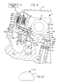
- FIG. 3 a cross-sectional view of the valve control system 1 of the present invention is shown.
- the actuator assembly 16 has been energized by the control unit 51 and the actuator arm 17 has been rotated by action of the plunger 45 to engage the latch member 28 when the cam lobe 20 engaged the roller follower 24 and caused the rocker arm assembly 14 to be rotated on the plunger 30 thereby allowing the actuator arm 17 to engage the latch member 28.
- the valve control system 1 of the present invention does not have to be timed to the rotation of the camshaft 4.
- the latch member 28 has just been unloaded from the inner rocker arm 18 and both the arm spring 39 and the latch spring 29 have been further compressed as compared to that shown in FIG. 1.
- the latch member 28 has been moved slightly rightward and is shown preloaded by the compression of arm spring 39 and the latch spring 29 to move fully rightward so as to disengage the inner rocker arm 18 from the outer rocker arm 22 when the latch member 28 is fully unloaded.
- FIG. 4 a cross-sectional view of the valve control system 1 of the present invention is shown where the rocker arm assembly 14 is in the inactive mode.
- the actuator arm 17 is shown fully extended by the arm spring 39 and has moved the latch member 28, which is unloaded, fully to the right thereby unlinking the inner rocker arm 18 and the outer rocker arm 22.
- the rocker arm assembly 14 is in the inactive mode where the engine poppet valve 6 does not open in response to the cam lobe 20.
- the latch spring 29 is compressed by the actuator arm 17 since the preload and rate of the arm spring 39 is higher than the preload and rate of the latch spring 29.
- FIG. 5 The perspective view of the rocker arm assembly 14 as shown in FIG. 5 illustrates the inner rocker arm 18 surrounded by the outer arm 22 where the inner rocker arm 18 contacts and pivots on the link pin 11 (see FIG. 1) while the outer rocker arm 22 when linked to the inner rocker arm 18 by latch member 28 contacts and actuates the engine poppet valve 5 when the latch member 28 is in the active position.
- the cam roller follower 24 rotates on roller pin 25 which is supported in the inner rocker arm 18.
- the latch member 28, which is only partially shown, is biased into the active position by the latch spring 29 where the contact plate 41 contacts the inner rocker arm at contact surface 18A and is supported by the outer rocker arm 22 when the rocker arm assembly is in the active mode.
- the link pin 11 (see FIG. 1) holds the inner and outer rocker arms 18 and 22 and the latch member 28 in the proper orientation while allowing relative rotation between the inner and outer rocker arms 18 and 22, and axial motion of the latch member 28 due to the elongated link pin aperture 21 formed in both sides of latch member 28.
- the link pin 11 extends through the latch member 28 and the outer rocker arm 22 while the inner rocker arm 18 pivots over link pin 11 and retains the three elements in the proper orientation while pivoting on the lash adjuster 5.
- the latch member 28 has a contact plate 41, the position of which determines when the rocker arm assembly 14 is in an active or inactive mode.
- the rocker arm assembly 14 is in the active mode and the latch member 28 provides a mechanical link between the inner and outer rocker arms 18 and 22 to open the engine poppet valve 6 in response to the camshaft 4 acting on the roller follower 24.
- the rocker arm assembly 14 is placed in an inactive mode where the inner arm 18 is not linked to the outer arm 22 and the engine poppet valve 6 is closed.
- the contact plate 41 As the contact plate 41, as part of the latch member 28, is moved toward the inner rocker arm 18, the contact plate 41 catches an edge of the inner rocker arm 18 at contact surface 18A and thereby mechanically links the inner and outer rocker arms 18 and 22 causing the engine poppet valve 6 to open and close in response to the cam lobe 20. As the contact plate 41 is moved away from the inner rocker arm 18, the inner rocker arm 18 no longer contacts the contact plate 41 and the inner rocker arm 18 moves in response to the camshaft 4 but its motion is not transferred to the outer rocker arm 22 or the engine poppet valve 6.
- the inner rocker arm 18 pivots over the link pin 11 at the plunger 30 and compresses the biasing spring 26 which is supported at one end by the inner rocker arm 18 and at a second end by the outer rocker arm 22.
- the biasing spring 26 functions to maintain contact between the cam roller follower 24 and the cam lobe 20 and to provide the proper compression load on the lash adjuster 5.
- the initial preload/position on the biasing spring 26 can be changed with the preload adjuster 31.
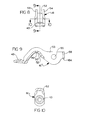
- FIG. 6 is an elevational view of the rocker arm assembly 14 of the present invention.
- the link pin 11 extends through the outer rocker arm 22 providing a rotational support on the plunger 30.
- the latch member 28 couples the inner rocker arm 18 to the outer rocker arm 22 at contact plate 41 and contact surface 18A which is part of the inner rocker arm 18.
- the latch spring 29 functions to bias the latch member 28 leftward to cause the latch member 28 to engage the contact surface 18A and normally shift the rocker arm assembly into the active mode.
- FIG. 7 an elevational view of the rocker arm assembly 14 of FIG. 6 is shown.
- the link pin 11 passes through the link pin aperture 21 which extends through the latch member 28, the outer rocker arm 22 and the inner rocker arm 18 pivots over it.
- the aperture 21 is elongated in the latch member 28 as compared to the outer rocker arm 22 to allow for the axial movement when the rocker arm assembly 14 is shifted from the active to the inactive mode.
- Thread 31A accommodates the preload/position adjuster 31 for adjustment of the preload/position on biasing spring 26 that regulates the amount of clearance between the inner rocker arm 18 and the outer rocker arm 22 at contact plate 41 thereby setting the operating clearance for each individual rocker arm assembly 14.
- FlGs. 6 and 7 show top and side plan views of the rocker arm assembly 14 of the present invention.
- the inner rocker arm 18 is generally surrounded by the outer rocker arm 22 where the latch member 28 is moved to cause the contact plate 41 to contact the inner rocker arm 18 for activation of the engine poppet valve 6 (active mode) or to not contact the inner rocker arm 18 for decoupling of the inner rocker arm 18 from the outer rocker arm 22 and deactivation of the engine poppet valve 6 (inactive mode).
- the latch spring 29 contacts the inner rocker arm 18 and the latch member 28 and provides a spring bias to force the latch member 28 leftward and specifically the contact plate 41 toward the inner rocker arm 18.
- the latch member 28 is spring biased toward the active mode.
- FIG. 8 is an elevational view of the inner rocker arm 18 of the present invention.
- the inner rocker arm 18 consists of two side walls 53 and 54 and a web portion 52 connecting the side walls 53 and 54.
- the lower spring support 43 is attached and formed as part of the web portion 52.
- FIG. 9 is a cross-sectional view of the inner rocker arm 18 of FIG. 7 taken along line 9-9.
- the web portion 52 of the inner rocker arm 18 is shown having an oil drain 49 formed in a location coinciding with the area of the inner rocker arm 18 that contacts and pivots over the link pin 11 on saddle portion 50 (see FIG. 1).
- a pin aperture 55 is formed in both of the side walls 53 and 54 to provide for support of the roller pin 25.
- An end portion 58 forms contact surface 18A which contacts the contact plate 41 (see FIG. 2) when the rocker arm assembly 14 is in the active mode. In the active mode, the actuator assembly 16 is not energized or the actuator assembly 16 has been energized by the control unit 51 and the latch member remains loaded thereby preventing movement and the latch spring 29 biases the latch member 28 into engagement.
- FIG. 10 is a cross-sectional view of the inner rocker arm 18 of FIG. 7 taken along line 10-10.
- the web portion 52 extends to form the lower spring support 43 on which the biasing spring 26 rides.
- the preload adjuster 31 contacts the side of the lower spring support 43 opposite to that of the biasing spring 26 to provide for adjustment of the relative length between the inner rocker arm 18 and the outer rocker arm 22 with the biasing spring 26 mounted therebetween thereby altering the position stop on the biasing spring 26 and the depth of the plunger 30 into the main body 32 of the lash adjuster 5.
- FIG. 11 is a side elevational view of the outer rocker arm 22 where a link pin aperture 61 is formed in both side walls 67 and 68 to provide support for the link pin 33.
- an upper spring support 57 is formed which, in conjunction with the lower spring support 43 found in the inner rocker arm 18 provides a secure mounting arrangement for the biasing spring 26.
- the biasing spring 26 provides a separation force between the inner and outer rocker arms 18 and 22 and forces the roller follower 24 into contact with the cam lobe 20 and loads the plunger 30 of the lash adjuster 5.
- a valve contact pad 59 is provided at the second end 22B of the outer rocker arm 22 for contacting the top of the valve stem of engine poppet valve 6 at valve engagement surface 22C.
- FIG. 12 is a top view of the outer rocker arm 22 of FIG. 10 more clearly showing the side walls 67 and 68 and both link pin apertures 61A and 61B which combine to form part of the link pin aperture 21.
- FIG. 13 is an end view of the outer rocker arm 22 of FIG. 11 more clearly showing the valve engagement surface 22C which contacts the end of the engine poppet valve 6 thereby transferring the motion provided by the camshaft 4 and the inner rocker arm 18 to the engine poppet valve 6 when the rocker arm assembly 14 is in an active mode. It also illustrates how the side wall 68 is formed to provide a support portion 69 for the preload adjuster 31 (see FIGS. 5 and 13).
- FIG. 14 is a cross-sectional view of the link pin 11 showing the pivoting section 71 where the link pin 11 contacts and pivots on the plunger 30.
- FIG. 15 is an end view of the link pin 11 showing the semicircular shape which allows the saddle portion 50 of the inner rocker arm 18 to pivot on the support surface 73 of the link pin 11.
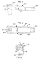
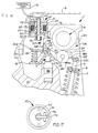
- FIG. 16 a cross-sectional view of an alternate embodiment of the present invention is shown.
- the actuator assembly 16' operates against a dual arm bellcrank 70 where the plunger 45' pushes against the first arm 72 of bellcrank 70 which pivots on pin 76 and the second arm 74 contacts the contact pad 48' of latch member 28' of rocker arm assembly 14'.
- the latch spring 29 is compressed between the contact pad 48' of latch member 28' and the outer rocker arm 22.
- the actuator assembly 16' is comprised of a solenoid having a case 15' and a coil 23' which is electrically energized by control unit 51 to create an electromagnetic field in stator 27' which magnetically attracts the armature 35' thereby compressing the actuator spring 44' against the retainer 47' which is attached to the plunger 45'.
- the plunger 45' is slidingly connected to the armature 35'. Upon energization of the coil 23', the plunger 45' is forced downward against the first arm 72 which moves and further compresses return spring 78 which is preloaded to force the bellcrank 70 clockwise to maintain contact between the first arm 72 and the plunger 45'.
- the second arm 74 of bellcrank 70 contacts the contact pad 48' and acts to force the latch member 28' rightward when the actuator assembly 16' is energized to shift the rocker arm assembly 14' into an inactive mode.
- FIG. 17 a partial bottom view of the solenoid actuator assembly 15' of the present invention is shown.
- the bellcrank 70 is rotatably supported on pin 76 which engages the case 15' of the solenoid actuator assembly 15'.
- the actuator spring 44' pushes against the plunger 45' and subsequently the bellcrank 70.
- the return spring 78 is not shown.
- the solenoid case 15' is shown as circular in cross-section, any shape could be utilized as known in the solenoid art.
Landscapes
- Engineering & Computer Science (AREA)
- Mechanical Engineering (AREA)
- General Engineering & Computer Science (AREA)
- Valve Device For Special Equipments (AREA)
- Valve-Gear Or Valve Arrangements (AREA)
Applications Claiming Priority (2)
| Application Number | Priority Date | Filing Date | Title |
|---|---|---|---|
| US622239 | 1990-12-06 | ||
| US08/622,239 US5623897A (en) | 1996-03-22 | 1996-03-22 | Engine valve control system using a latchable rocker arm activated by a solenoid mechanism |
Publications (2)
| Publication Number | Publication Date |
|---|---|
| EP0796982A1 EP0796982A1 (en) | 1997-09-24 |
| EP0796982B1 true EP0796982B1 (en) | 1999-09-08 |
Family
ID=24493452
Family Applications (1)
| Application Number | Title | Priority Date | Filing Date |
|---|---|---|---|
| EP97301308A Expired - Lifetime EP0796982B1 (en) | 1996-03-22 | 1997-02-27 | Engine valve control system using a latchable rocker arm activated by a solenoid mechanism |
Country Status (4)
| Country | Link |
|---|---|
| US (2) | US5623897A (enExample) |
| EP (1) | EP0796982B1 (enExample) |
| JP (1) | JP4068176B2 (enExample) |
| DE (1) | DE69700480T2 (enExample) |
Families Citing this family (68)
| Publication number | Priority date | Publication date | Assignee | Title |
|---|---|---|---|---|
| US5987973A (en) * | 1996-07-24 | 1999-11-23 | Honda Giken Kogyo Kabushiki Kaisha | Rotation detecting device of an engine |
| US5690066A (en) | 1996-09-30 | 1997-11-25 | Eaton Corporation | Engine valve control actuator with knee action linkage |
| US5697333A (en) * | 1997-02-20 | 1997-12-16 | Eaton Corporation | Dual lift actuation means |
| DE19801964A1 (de) * | 1998-01-21 | 1999-07-22 | Audi Ag | Vorrichtung zur Unterbrechung des Kraftflusses zwischen wenigstens einem Ventil und wenigstens einem Nocken einer Nockenwelle |
| GB2348246B (en) * | 1999-03-25 | 2002-11-13 | Ricardo Inc | Automotive valve rocker arms |
| US6497207B2 (en) | 2000-10-20 | 2002-12-24 | Delphi Technologies, Inc. | Deactivation roller hydraulic valve lifter |
| US7263956B2 (en) | 1999-07-01 | 2007-09-04 | Delphi Technologies, Inc. | Valve lifter assembly for selectively deactivating a cylinder |
| US6273040B1 (en) | 2000-05-04 | 2001-08-14 | William P. Curtis | Adjustable overhead rocker cam |
| US6314928B1 (en) * | 2000-12-06 | 2001-11-13 | Ford Global Technologies, Inc. | Rocker arm assembly |
| US6382153B1 (en) * | 2001-04-11 | 2002-05-07 | Delphi Technologies, Inc. | Partial internal guide for curved helical compression spring |
| US6318318B1 (en) * | 2001-05-15 | 2001-11-20 | Ford Global Technologies, Inc. | Rocker arm assembly |
| JP4603213B2 (ja) * | 2001-09-03 | 2010-12-22 | 本田技研工業株式会社 | 電磁弁装置 |
| DE10146129A1 (de) | 2001-09-19 | 2003-04-03 | Ina Schaeffler Kg | Schaltelement für einen Ventiltrieb einer Brennkraftmaschine |
| WO2003042506A1 (de) * | 2001-11-14 | 2003-05-22 | Ina-Schaeffler Kg | Schlepphebel eines ventiltriebs einer brennkraftmaschine |
| US6499451B1 (en) * | 2001-12-17 | 2002-12-31 | Delphi Technologies, Inc. | Control system for variable activation of intake valves in an internal combustion engine |
| US6591798B2 (en) | 2001-12-17 | 2003-07-15 | Delphi Technologies, Inc. | Variable valve actuation assembly for an internal combustion engine |
| ATE300665T1 (de) | 2002-02-06 | 2005-08-15 | Ina Schaeffler Kg | Schaltelement für einen ventiltrieb einer brennkraftmaschine |
| US6532920B1 (en) * | 2002-02-08 | 2003-03-18 | Ford Global Technologies, Inc. | Multipositional lift rocker arm assembly |
| US7007643B2 (en) | 2002-12-30 | 2006-03-07 | Caterpillar Inc. | Engine valve actuation system |
| US6971349B2 (en) * | 2002-08-22 | 2005-12-06 | Ford Global Technologies, Llc | Integrated solenoid board and cam ladder |
| US6805083B2 (en) * | 2002-10-10 | 2004-10-19 | Ford Global Technologies, Llc | Cam cover gasket |
| US7140333B2 (en) * | 2002-11-12 | 2006-11-28 | Volvo Lastvagnar Ab | Apparatus for an internal combustion engine |
| DE10318295A1 (de) * | 2003-04-23 | 2004-11-11 | Ina-Schaeffler Kg | Schlepphebel eines Ventiltriebs einer Brennkraftmaschine |
| US6935295B2 (en) * | 2003-09-24 | 2005-08-30 | General Motors Corporation | Combustion-assisted engine start/stop operation with cylinder/valve deactivation |
| US7677213B2 (en) * | 2005-08-04 | 2010-03-16 | Timken Us Llc | Deactivating roller finger follower |
| DE102005048984A1 (de) * | 2005-10-13 | 2007-04-19 | Schaeffler Kg | Schaltbarer Schlepphebel |
| DE102006033403A1 (de) * | 2006-07-19 | 2008-01-24 | Mahle International Gmbh | Nockentrieb |
| US7603972B2 (en) * | 2006-10-10 | 2009-10-20 | Hyundai Motor Company | Cylinder deactivation system for vehicle and variable valve lift system using the same |
| DE102008057830A1 (de) | 2007-11-21 | 2009-05-28 | Schaeffler Kg | Abschaltbarer Stößel |
| US10415439B2 (en) | 2008-07-22 | 2019-09-17 | Eaton Intelligent Power Limited | Development of a switching roller finger follower for cylinder deactivation in internal combustion engines |
| US9938865B2 (en) | 2008-07-22 | 2018-04-10 | Eaton Corporation | Development of a switching roller finger follower for cylinder deactivation in internal combustion engines |
| US8985074B2 (en) | 2010-03-19 | 2015-03-24 | Eaton Corporation | Sensing and control of a variable valve actuation system |
| US9016252B2 (en) | 2008-07-22 | 2015-04-28 | Eaton Corporation | System to diagnose variable valve actuation malfunctions by monitoring fluid pressure in a hydraulic lash adjuster gallery |
| US9284859B2 (en) | 2010-03-19 | 2016-03-15 | Eaton Corporation | Systems, methods, and devices for valve stem position sensing |
| US9267396B2 (en) | 2010-03-19 | 2016-02-23 | Eaton Corporation | Rocker arm assembly and components therefor |
| US9228454B2 (en) | 2010-03-19 | 2016-01-05 | Eaton Coporation | Systems, methods and devices for rocker arm position sensing |
| US9581058B2 (en) | 2010-08-13 | 2017-02-28 | Eaton Corporation | Development of a switching roller finger follower for cylinder deactivation in internal combustion engines |
| US20190309663A9 (en) | 2008-07-22 | 2019-10-10 | Eaton Corporation | Development of a switching roller finger follower for cylinder deactivation in internal combustion engines |
| WO2015134466A1 (en) | 2014-03-03 | 2015-09-11 | Eaton Corporation | Valve actuating device and method of making same |
| US9291075B2 (en) | 2008-07-22 | 2016-03-22 | Eaton Corporation | System to diagnose variable valve actuation malfunctions by monitoring fluid pressure in a control gallery |
| US8215275B2 (en) * | 2010-08-13 | 2012-07-10 | Eaton Corporation | Single lobe deactivating rocker arm |
| US11181013B2 (en) | 2009-07-22 | 2021-11-23 | Eaton Intelligent Power Limited | Cylinder head arrangement for variable valve actuation rocker arm assemblies |
| US9194261B2 (en) | 2011-03-18 | 2015-11-24 | Eaton Corporation | Custom VVA rocker arms for left hand and right hand orientations |
| US10087790B2 (en) | 2009-07-22 | 2018-10-02 | Eaton Corporation | Cylinder head arrangement for variable valve actuation rocker arm assemblies |
| US8196556B2 (en) * | 2009-09-17 | 2012-06-12 | Delphi Technologies, Inc. | Apparatus and method for setting mechanical lash in a valve-deactivating hydraulic lash adjuster |
| US9885258B2 (en) | 2010-03-19 | 2018-02-06 | Eaton Corporation | Latch interface for a valve actuating device |
| US9874122B2 (en) | 2010-03-19 | 2018-01-23 | Eaton Corporation | Rocker assembly having improved durability |
| WO2011129836A1 (en) * | 2010-04-16 | 2011-10-20 | International Engine Intellectual Property Company, Llc | Engine braking system using spring loaded valve |
| WO2016028465A1 (en) * | 2014-08-18 | 2016-02-25 | Eaton Corporation | Magnetically latching flux-shifting electromechanical actuator |
| US10180089B2 (en) * | 2014-08-18 | 2019-01-15 | Eaton Intelligent Power Limited | Valvetrain with rocker arm housing magnetically actuated latch |
| US10781726B2 (en) * | 2015-06-04 | 2020-09-22 | Eaton Intelligent Power Limited | Electrically latching rocker arm assembly having built-in OBD functionality |
| US10371016B2 (en) * | 2015-06-04 | 2019-08-06 | Eaton Intelligent Power Limited | Electrically latching rocker arm assembly having built-in OBD functionality |
| WO2017091799A1 (en) * | 2015-11-25 | 2017-06-01 | Eaton Corporation | Rocker arm assembly having an electrical connection made between abutting surfaces that undergo relative motion |
| US10316709B2 (en) * | 2015-09-21 | 2019-06-11 | Eaton Intelligent Power Limited | Electromechanical valve lash adjuster |
| WO2017091798A1 (en) * | 2015-11-25 | 2017-06-01 | Eaton Corporation | Hydraulic lash adjuster with electromechanical rocker arm latch linkage |
| GB201603344D0 (en) * | 2016-02-26 | 2016-04-13 | Eaton Srl | Actuation apparatus |
| WO2017194291A1 (en) * | 2016-05-12 | 2017-11-16 | Eaton Srl | Rocker arm |
| JP6509956B2 (ja) * | 2017-06-30 | 2019-05-08 | 本田技研工業株式会社 | 可変動弁装置 |
| GB201710959D0 (en) * | 2017-07-07 | 2017-08-23 | Eaton Srl | Actuator arrangement |
| GB201712662D0 (en) * | 2017-08-07 | 2017-09-20 | Eaton Srl | Actuation apparatus |
| KR101924869B1 (ko) * | 2017-08-10 | 2018-12-05 | (주)모토닉 | 엔진의 가변밸브 리프트 장치 |
| DE112018003877T5 (de) * | 2017-08-25 | 2020-04-16 | Eaton Intelligent Power Limited | Deaktivierende spieleinstelleinrichtung mit niedrigerem hub bei kombination mit einem zwei-stufigen variablen ventilhub-kipphebel |
| JP7004152B2 (ja) * | 2018-01-12 | 2022-01-21 | トヨタ自動車株式会社 | 動弁機構 |
| JP6969395B2 (ja) * | 2018-01-17 | 2021-11-24 | トヨタ自動車株式会社 | ロッカアーム |
| GB201803573D0 (en) * | 2018-03-06 | 2018-04-18 | Eaton Intelligent Power Ltd | Actuation apparatus |
| WO2019228670A1 (en) * | 2018-05-30 | 2019-12-05 | Eaton Intelligent Power Limited | Valvetrain with electromechanical latch actuator |
| DE102018116070A1 (de) * | 2018-07-03 | 2020-01-09 | Schaeffler Technologies AG & Co. KG | Modul für einen hubvariablen Ventiltrieb einer Brennkraftmaschine |
| US11982211B2 (en) | 2018-09-04 | 2024-05-14 | Eaton Intelligent Power Limited | Direct-acting solenoid having variable triggering timing for electro-mechanical valvetrain and actuation levers for switching rocker arms |
Family Cites Families (9)
| Publication number | Priority date | Publication date | Assignee | Title |
|---|---|---|---|---|
| DE2753197A1 (de) * | 1976-12-15 | 1978-06-22 | Eaton Corp | Ventilsteuervorrichtung |
| US4203397A (en) * | 1978-06-14 | 1980-05-20 | Eaton Corporation | Engine valve control mechanism |
| US4768467A (en) * | 1986-01-23 | 1988-09-06 | Fuji Jukogyo Kabushiki Kaisha | Valve operating system for an automotive engine |
| DE4223475A1 (de) * | 1992-07-16 | 1994-01-20 | Audi Ag | Ventilbetätigungsmechanismus |
| US5445116A (en) * | 1992-12-22 | 1995-08-29 | Unisia Jecs Corporation | Hydraulic variable lift engine valve gear |
| US5544626A (en) * | 1995-03-09 | 1996-08-13 | Ford Motor Company | Finger follower rocker arm with engine valve deactivator |
| US5524580A (en) * | 1995-05-11 | 1996-06-11 | Eaton Corporation | Adjusting mechanism for a valve control system |
| US5529033A (en) * | 1995-05-26 | 1996-06-25 | Eaton Corporation | Multiple rocker arm valve control system |
| US5584267A (en) * | 1995-12-20 | 1996-12-17 | Eaton Corporation | Latchable rocker arm mounting |
-
1996
- 1996-03-22 US US08/622,239 patent/US5623897A/en not_active Expired - Lifetime
- 1996-10-29 US US08/744,723 patent/US5682848A/en not_active Expired - Lifetime
-
1997
- 1997-02-27 DE DE69700480T patent/DE69700480T2/de not_active Expired - Lifetime
- 1997-02-27 EP EP97301308A patent/EP0796982B1/en not_active Expired - Lifetime
- 1997-03-21 JP JP06835797A patent/JP4068176B2/ja not_active Expired - Lifetime
Also Published As
| Publication number | Publication date |
|---|---|
| US5623897A (en) | 1997-04-29 |
| JP4068176B2 (ja) | 2008-03-26 |
| EP0796982A1 (en) | 1997-09-24 |
| DE69700480T2 (de) | 2000-05-04 |
| DE69700480D1 (de) | 1999-10-14 |
| US5682848A (en) | 1997-11-04 |
| JPH108929A (ja) | 1998-01-13 |
Similar Documents
| Publication | Publication Date | Title |
|---|---|---|
| EP0796982B1 (en) | Engine valve control system using a latchable rocker arm activated by a solenoid mechanism | |
| EP0767296B1 (en) | Engine valve control system using a latchable rocker arm | |
| US5690066A (en) | Engine valve control actuator with knee action linkage | |
| JPH108929A5 (enExample) | ||
| US5544626A (en) | Finger follower rocker arm with engine valve deactivator | |
| US6499451B1 (en) | Control system for variable activation of intake valves in an internal combustion engine | |
| US6997152B2 (en) | Lock-pin cartridge for a valve deactivation rocker arm assembly | |
| US6668775B2 (en) | Lock-pin cartridge for a two-step finger follower rocker arm | |
| US5697333A (en) | Dual lift actuation means | |
| US10465572B2 (en) | Actuation apparatus for variable valve drive | |
| EP0747575A1 (en) | Adjusting mechanism for a valve control system | |
| JPH09177526A (ja) | 内燃機関のブレーキシステム | |
| CN101365865B (zh) | 带有停阀摇臂的气门控制系统 | |
| CN112469887A (zh) | 用于启用可变气门致动的ii型气门机构 | |
| US10704429B2 (en) | Switchable rocker arm | |
| US20240133322A1 (en) | Bidirectional latch pin assembly, switchable rocker arm, and valvetrain assembly | |
| EP4051883A1 (en) | Rocker arm assemblies | |
| JPH1068308A (ja) | バルブ制御システム | |
| EP1568849B1 (en) | Rocker arm assembly for a valve train | |
| JPH0218246Y2 (enExample) | ||
| JPH0819844B2 (ja) | エンジンのバルブ駆動装置 | |
| JPH0478807B2 (enExample) |
Legal Events
| Date | Code | Title | Description |
|---|---|---|---|
| PUAI | Public reference made under article 153(3) epc to a published international application that has entered the european phase |
Free format text: ORIGINAL CODE: 0009012 |
|
| AK | Designated contracting states |
Kind code of ref document: A1 Designated state(s): DE FR GB IT |
|
| 17P | Request for examination filed |
Effective date: 19980227 |
|
| GRAG | Despatch of communication of intention to grant |
Free format text: ORIGINAL CODE: EPIDOS AGRA |
|
| 17Q | First examination report despatched |
Effective date: 19981008 |
|
| GRAG | Despatch of communication of intention to grant |
Free format text: ORIGINAL CODE: EPIDOS AGRA |
|
| GRAH | Despatch of communication of intention to grant a patent |
Free format text: ORIGINAL CODE: EPIDOS IGRA |
|
| GRAH | Despatch of communication of intention to grant a patent |
Free format text: ORIGINAL CODE: EPIDOS IGRA |
|
| GRAA | (expected) grant |
Free format text: ORIGINAL CODE: 0009210 |
|
| AK | Designated contracting states |
Kind code of ref document: B1 Designated state(s): DE FR GB IT |
|
| REF | Corresponds to: |
Ref document number: 69700480 Country of ref document: DE Date of ref document: 19991014 |
|
| ITF | It: translation for a ep patent filed | ||
| ET | Fr: translation filed | ||
| PLBE | No opposition filed within time limit |
Free format text: ORIGINAL CODE: 0009261 |
|
| STAA | Information on the status of an ep patent application or granted ep patent |
Free format text: STATUS: NO OPPOSITION FILED WITHIN TIME LIMIT |
|
| 26N | No opposition filed | ||
| REG | Reference to a national code |
Ref country code: GB Ref legal event code: IF02 |
|
| REG | Reference to a national code |
Ref country code: FR Ref legal event code: PLFP Year of fee payment: 20 |
|
| PGFP | Annual fee paid to national office [announced via postgrant information from national office to epo] |
Ref country code: IT Payment date: 20160209 Year of fee payment: 20 Ref country code: DE Payment date: 20160302 Year of fee payment: 20 |
|
| PGFP | Annual fee paid to national office [announced via postgrant information from national office to epo] |
Ref country code: GB Payment date: 20160127 Year of fee payment: 20 Ref country code: FR Payment date: 20160125 Year of fee payment: 20 |
|
| REG | Reference to a national code |
Ref country code: DE Ref legal event code: R071 Ref document number: 69700480 Country of ref document: DE |
|
| REG | Reference to a national code |
Ref country code: GB Ref legal event code: PE20 Expiry date: 20170226 |
|
| PG25 | Lapsed in a contracting state [announced via postgrant information from national office to epo] |
Ref country code: GB Free format text: LAPSE BECAUSE OF EXPIRATION OF PROTECTION Effective date: 20170226 |