EP0796936A2 - Method and device to pneumatically assist the insertion and the tensioning of a weft thread on looms - Google Patents
Method and device to pneumatically assist the insertion and the tensioning of a weft thread on looms Download PDFInfo
- Publication number
- EP0796936A2 EP0796936A2 EP97102836A EP97102836A EP0796936A2 EP 0796936 A2 EP0796936 A2 EP 0796936A2 EP 97102836 A EP97102836 A EP 97102836A EP 97102836 A EP97102836 A EP 97102836A EP 0796936 A2 EP0796936 A2 EP 0796936A2
- Authority
- EP
- European Patent Office
- Prior art keywords
- weft thread
- weft
- thread
- nozzle
- pneumatically
- Prior art date
- Legal status (The legal status is an assumption and is not a legal conclusion. Google has not performed a legal analysis and makes no representation as to the accuracy of the status listed.)
- Withdrawn
Links
- 238000003780 insertion Methods 0.000 title claims abstract description 33
- 230000037431 insertion Effects 0.000 title claims abstract description 33
- 238000000034 method Methods 0.000 title claims description 25
- 238000009941 weaving Methods 0.000 claims description 15
- 238000012544 monitoring process Methods 0.000 claims 2
- 239000004744 fabric Substances 0.000 description 8
- 239000003638 chemical reducing agent Substances 0.000 description 3
- 230000003213 activating effect Effects 0.000 description 2
- 238000010276 construction Methods 0.000 description 2
- 238000007726 management method Methods 0.000 description 2
- 210000000056 organ Anatomy 0.000 description 2
- 230000001133 acceleration Effects 0.000 description 1
- 238000007664 blowing Methods 0.000 description 1
- 230000001276 controlling effect Effects 0.000 description 1
- 238000004519 manufacturing process Methods 0.000 description 1
- 230000001105 regulatory effect Effects 0.000 description 1
Images

Classifications
-
- D—TEXTILES; PAPER
- D03—WEAVING
- D03D—WOVEN FABRICS; METHODS OF WEAVING; LOOMS
- D03D47/00—Looms in which bulk supply of weft does not pass through shed, e.g. shuttleless looms, gripper shuttle looms, dummy shuttle looms
- D03D47/34—Handling the weft between bulk storage and weft-inserting means
Definitions
- the invention relates to a method and a device for pneumatically supporting the insertion and tensioning of a weft thread to be inserted into a shed of a loom according to the preamble of claims 1 and 5.
- a pneumatically acting thread brake instead of a thread brake with mechanically acting thread brake elements when processing synthetic weft yarns, in order to cause deformation phenomena on the weft thread caused by excessive friction the mechanical thread braking elements.
- a pneumatic thread brake consists of a long guide tube with a small cross-section for the passage of the weft thread. At one end of the guide tube there is an injector tube directed counter to the direction of movement of the weft thread, which is connected to a compressed air source via a shut-off valve which can be actuated in the machine cycle.
- weft brakes cannot be dispensed with on fast-running weaving machines.
- the braking force of the weft brakes can be controlled or regulated in such weaving machines. In this respect, these weft brakes can have no influence on the processing of synthetic weft threads.
- a pneumatic thread tensioning device which is arranged between a thread supply and the weaving machine itself.
- this device uses a tubular element with an inner passage which extends over the length of the tubular element and through which the weft thread is guided.
- a second tubular element surrounds the first tubular element such that the inner wall of the second element and the outer wall of the first element form an outer passage.
- Air flow is effective through the outer passage in a direction that is the same as the direction of thread take-off.
- An opening directs the flow of air from the outer passage into the inner passage so that the direction of the air flow is reversed. The air thus flows in a direction that is opposite to the thread take-off and thus generates a certain tension force in the weft thread.
- the construction of such a thread tensioning device is expensive. Another disadvantage is that this can only be used for tensioning the weft against its direction of withdrawal.
- EP 0 617 153 A1 discloses a method for influencing the movement of a weft thread which can be drawn off from a supply bobbin and runs towards a weft insertion device of a weaving machine, and a weaving machine for carrying out the method.
- the background of the known solution is to allow a gentle guidance of the weft thread to be fed to the weft insertion device and to avoid sudden stressing of the weft thread due to the withdrawal of a weft thread deflection.
- the weft thread is additionally accelerated by a compressed air nozzle arranged between the supply spool and the weft insertion device within a predetermined fraction of the weaving cycle after the weft thread is returned from the deflection position.
- the brief additional acceleration emanating from the compressed air nozzle is intended to ensure gentle guiding of the weft thread and to prevent the occurrence of a "stretching impact" when the weft thread is stretched out.
- the known EP 0 617 153 A1 does not give the person skilled in the art instructions for this, as in a weaving machine in which the weft threads are joined by means of reaching elements Filing organ are submitted, a necessary weft tension before and / or during the handover can be guaranteed and how in connection with this the entry process of the weft to be entered in the shed can be supported at least in the initial phase.
- the weft thread for entry into the shed of a weaving machine can be caused by various circumstances, e.g. Interlocking of the weft threads with each other or through operator intervention while the machine is at a standstill, between an existing weft thread brake and the fabric edge. This increases the likelihood of the weft thread not being correctly delivered to the insertion element and also the failure to grasp the weft thread by an insertion element which guides the weft thread through the shed. This also increases the likelihood of a weaving machine stop.
- the object of the invention is to provide a method which influences both the tension force of a weft thread before and / or during the delivery of the weft thread to a weft thread insertion member and the tension force of the weft thread at least in the initial phase of the insertion process. Furthermore, it is an object of the invention to provide a device for carrying out the method, which has a simple construction and is inexpensive to manufacture.
- Essential to the invention is the arrangement and control of at least one pneumatically active device consisting of two air nozzles or preferably a double air nozzle.
- the device is arranged between a thread delivery device and components which are arranged downstream of each thread delivery device.
- the air nozzles are intended both to support the insertion of the weft thread and to tighten a loosened weft thread in the area between the weft thread brake and a so-called clamping scissors at the fabric edge.
- One of the two nozzles acts in the drawing direction of the weft thread, the other opposite the drawing direction.
- the weft thread entry is supported by activating the weft thread pulling direction acting first nozzle.
- the nozzle pneumatically applies the weft.
- the thread tension during weft insertion is reduced, i.e. the thread of the entry member is supported, which is otherwise applied solely by the entry member.
- the weft thread is tightened against the pull-off direction by activating the nozzle acting against the pull-off direction.
- the weft brake is preferably open, the weft to be entered is held taut between the weft brake and the fabric edge.
- the device proposed for practicing the method preferably consists of a double nozzle which, seen in the direction of withdrawal of the weft thread, is located after a thread delivery device and before the entry of a controllable weft thread brake, one of the nozzles acting in the direction of withdrawal of the weft thread and the second nozzle counteracting the direction of withdrawal .
- the weft thread between the clamping scissors on the fabric edge and the thread brake is kept taut, at least until it is taken over by the entry element.
- the thread entry is pneumatically supported by the nozzle arrangement, i.e. the nozzle can be active in the take-off direction during the entry of the thread into the shed and thus reduce the thread tension. This reduces the risk of a weft break during the entry.
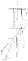
- the shed 10 is opened, into which a weft thread 11 is inserted by means of an insertion element 7, so that a fabric 6 is formed from weft threads 11 and warp threads 12.
- the weft thread 11 to be inserted is located on a supply spool 8, through which the thread is provided by means of a thread delivery device 2.
- the weft thread 11 is guided via a controllable weft thread brake 3 and a weft thread monitor 4 to a weft thread delivery 5, which serves to place the weft thread 11 before the weft insertion in such a way that it can be reliably gripped by the entry element 7 and entered into the shed 10.
- a combined clamping and cutting device 9 is provided in the area of the fabric edge 6a, which cuts the weft 11 after successful entry into the shed 10 and fixes the position of the beginning of the weft ready for entry in position until the ready weft in the shed 10 is entered.
- an air nozzle 1 is arranged in front of the weft brake 3, which is designed as a double nozzle with a first nozzle 1.1 and a second nozzle 1.2.
- the weft thread passes through the air nozzle 1, e.g. the nozzle 1.1 is effective in the direction of withdrawal, i.e. the weft 11 can be moved through the nozzle 1.1 in the take-off direction.
- the nozzle 1.2 is then effective against the direction of withdrawal, i.e. the weft thread can be moved in the direction of the thread delivery device.
- the weft After a weft break or at the beginning of the weaving process, the weft must be threaded from the thread delivery device 2 via the weft brake 3, the weft monitor 4, the weft feeder 5 to the entry element 7 and clamping scissors 9.
- This threading process is advantageously supported by the nozzle 1 provided according to the invention, in that the weft thread is inserted into the nozzle 1.1 and is blown or pulled, for example, by this or by the nozzle 1.2 through the opened weft brake 3 and the weft monitor 4. This significantly simplifies the threading process.
- the weft thread can, for example can be moved through the nozzle 1.2 against its pull-off direction, the weft brake 3 being controllable into an open position at least for the duration of the blowing process of the nozzle 1.2.
- the backward movement of the weft thread ensures that the weft thread is held taut in the important area between the weft thread addition 5 and the clamping scissors 9 arranged on the fabric edge 6a, so that it can be reliably gripped by the entry element 7.
- FIG. 2 shows a control for the pneumatic loading of the weft thread 11 in or against its withdrawal direction through the nozzle 1.1 or 1.2.
- the nozzle 1.1 has a connection 1.1a for a pressure line and the nozzle 1.2 has a connection 1.2a for a pressure line.
- the entrance to the weft 11 is the free end of the nozzle 1.1 and the exit to the weft 11 is the free end of the nozzle 1.2.
- the connection 1.1a is connected to a pressure line 13 via an electrically controllable solenoid valve 14 and a pressure reducer 16 to the pressure source 17.
- connection 1.2a is connected to a pressure line 15 via an electrically controllable solenoid valve 18 and the pressure reducer 16 to the pressure source 17.
- the pressure line 15 branches off from the pressure line 13 in front of the solenoid valve 18 at point 19.
- the solenoid valve 14 is connected via a line 20 and the solenoid valve 18 is connected to the machine control 22 in a signal-transmitting manner.
- the functional sequence of the components of the weaving machine responsible for the weft insertion is programmed in the machine control 22.
- the programming contains not only times and time for actuating the solenoid valves 14, 18 for the pneumatic loading of the weft thread before the weft insertion or in the initial phase of the weft insertion, but also times and time for actuating the solenoid valves 14, 18 for the purpose Influencing the weft tension during the weft insertion process are programmed.
- the influence of the nozzles 1.1 and 1.2 is particularly relevant in rapier weaving machines, in which the weft thread is inserted through a first entry element up to approximately the middle of the shed and is taken over by a second entry element which carries the weft thread completely through the shed.
- a further advantage of the method according to the invention is thus that the weft tension can be influenced pneumatically over the duration of the weft insertion process.
- a mechanical weft brake per thread type could thus be dispensed with.
Abstract
Description
Die Erfindung betrifft ein Verfahren und eine Vorrichtung zum pneumatischen Unterstützen des Eintragens und Spannens eines in ein Webfach einer Webmaschine einzutragenden Schußfadens nach dem Oberbegriff des Anspruchs 1 und 5.The invention relates to a method and a device for pneumatically supporting the insertion and tensioning of a weft thread to be inserted into a shed of a loom according to the preamble of
Zum Beeinflussen der Spannkraft eines in ein Webfach einer Webmaschine einzutragenden Schußfadens ist aus dem DE-Gebrauchsmuster 70 22 965 bekannt, beim Verarbeiten synthetischer Schußgarne anstelle einer Fadenbremse mit mechanisch wirkenden Fadenbremsorganen eine pneumatisch wirkende Fadenbremse einzusetzen, um Deformierungserscheinungen am Schußfaden, hervorgerufen durch übermäßige Reibung an den mechanischen Fadenbremsorganen, zu vermeiden.
Eine solche pneumatische Fadenbremse besteht aus einem langen Führungsrohr geringen Querschnitts für den Durchlauf des Schußfadens. An einem Ende des Führungsrohres ist ein entgegen der Bewegungsrichtung des Schußfadens gerichtetes Injektorrohr angebracht, das über ein im Maschinentakt betätigbares Absperrventil mit einer Druckluftquelle verbunden ist.
Zur Erleichterung des Schußfadeneintritts in das Führungsrohr ist das andere Ende des Rohres trichterförmig erweitert.
Auf schnell lauffenden Webmaschinen kann auf Schußfadenbremsen nicht grundsätzlich verzichtet werden. Die Bremskraft der Schußfadenbremsen ist in derartigen Webmaschinen steuer- bzw. regelbar. Insoweit können diese Schußfadenbremsen ohne Einfluß auf die Verarbeitung synthetischer Schußfäden sein.To influence the tension force of a weft thread to be inserted into a shed of a loom, it is known from DE utility model 70 22 965 to use a pneumatically acting thread brake instead of a thread brake with mechanically acting thread brake elements when processing synthetic weft yarns, in order to cause deformation phenomena on the weft thread caused by excessive friction the mechanical thread braking elements.
Such a pneumatic thread brake consists of a long guide tube with a small cross-section for the passage of the weft thread. At one end of the guide tube there is an injector tube directed counter to the direction of movement of the weft thread, which is connected to a compressed air source via a shut-off valve which can be actuated in the machine cycle.
To facilitate the entry of the weft thread into the guide tube, the other end of the tube is widened in a funnel shape.
In general, weft brakes cannot be dispensed with on fast-running weaving machines. The braking force of the weft brakes can be controlled or regulated in such weaving machines. In this respect, these weft brakes can have no influence on the processing of synthetic weft threads.
Aus der DE 36 03 913 A1 ist eine pneumatische Fadenspanneinrichtung bekannt, die zwischen einem Fadenvorrat und der Webmaschine selbst angeordnet ist.
Zur Erzielung einer Spannkraft auf den Schußfaden entgegen der Fadenabzugsrichtung bedient sich diese Einrichtung eines röhrenförmigen Elements mit einem inneren Durchlaß, der sich über die Länge des röhrenförmigen Elements erstreckt und durch das der Schußfaden geführt ist.From DE 36 03 913 A1 a pneumatic thread tensioning device is known, which is arranged between a thread supply and the weaving machine itself.
In order to achieve a tension force on the weft thread against the thread take-off direction, this device uses a tubular element with an inner passage which extends over the length of the tubular element and through which the weft thread is guided.
Ein zweites röhrenförmiges Element umgibt das erste röhrenförmige Element so, daß die innere Wandung des zweiten Elements und die äußere Wandung des ersten Elements einen äußeren Durchlaß bildet.
Eine Luftströmung ist durch den äußeren Durchlaß in einer Richtung wirksam, die die gleiche ist, wie die Richtung des Fadenabzugs.
Eine Öffnung lenkt die Luftströmung von dem äußeren Durchlaß in den inneren Durchlaß so, daß die Richtung der Luftströmung umgekehrt wird. Die Luft strömt damit in einer Richtung, die den Fadenabzug entgegengerichtet ist und somit eine gewisse Spannkraft in dem Schußfaden erzeugt.
Der konstruktive Aufbau einer solchen Fadenspanneinrichtung ist kostspielig.
Nachteilig ist zudem, daß diese ausschließlich zum Spannen des Schußfadens entgegen seiner Abzugsrichtung Verwendung finden kann.
In Webmaschinen mit mechanisch oder elektromechanisch betätigten Fadenhinreichemitteln, die den Schußfaden einem Eintragsorgan zum Eintragen in ein Webfach vorlegen, wäre es von Vorteil, eine Vorrichtung zu verwenden, die sowohl ein Spannen des Schußfadens vor und/oder während des Fadenhinreichens gewährleistet als auch den Eintragsprozeß des Schußfadens wenigstens in der Anfangsphase unterstützt. Die vorbekannte pneumatische Fadenspanneinrichtung unterbreitet dafür allerdings keine Lösung.A second tubular element surrounds the first tubular element such that the inner wall of the second element and the outer wall of the first element form an outer passage.
Air flow is effective through the outer passage in a direction that is the same as the direction of thread take-off.
An opening directs the flow of air from the outer passage into the inner passage so that the direction of the air flow is reversed. The air thus flows in a direction that is opposite to the thread take-off and thus generates a certain tension force in the weft thread.
The construction of such a thread tensioning device is expensive.
Another disadvantage is that this can only be used for tensioning the weft against its direction of withdrawal.
In looms with mechanically or electromechanically actuated thread supply means, which present the weft thread to an entry element for entry into a shed, it would be advantageous to use a device which ensures both a tensioning of the weft thread before and / or during the thread passing as well as the entry process of the Weft thread supported at least in the initial phase. However, the previously known pneumatic thread tensioning device does not come up with a solution for this.
Des weiteren ist aus der EP 0 617 153 A1 ein Verfahren zum Beeinflussen der Bewegung eines von einer Vorratsspule abziehbaren und hin zu einer Schußeintragseinrichtung einer Webmaschine laufenden Schußfadens und eine Webmaschine zur Durchführung des Verfahrens bekannt.
Hintergrund der bekannten Lösung ist eine schonende Führung des der Schußeintragseinrichtung zuzuführenden Schußfadens zu ermöglichen und eine schlagartige Beanspruchung des Schußfadens aufgrund der Zurücknahme einer Schußfadenauslenkung zu vermeiden.
Gemäß der offenbarten Lösung wird der Schußfaden durch eine zwischen der Vorratsspule und der Schußeintragseinrichtung eingeordneten Druckluftdüse zusätzlich innerhalb eines vorbestimmten Bruchteils des Webzyklus beschleunigt, nachdem der Schußfaden aus der Auslenkposition zurückgeführt ist.
Die kurzzeitige zusätzliche, von der Druckluftdüse ausgehende Beschleunigung soll eine schonende Führung des Schußfadens gewährleisten und das Entstehen eines "Streckschlages" beim Ausstrecken des Schußfadens verhindern.
Die bekannte EP 0 617 153 A1 gibt dem Fachmann keine Anleitung dafür, wie in einer Webmaschine, in der die Schußfäden mittels Hinreicheelementen einem Eintragsorgan vorgelegt werden, eine notwendige Schußfadenspannung vor und/oder während des Hinreichens gewährleistet werden kann und wie im Zusammenhang damit der Eintragsprozeß des in das Webfach einzutragenden Schußfadens wenigstens in der Anfangsphase unterstützt werden kann.Furthermore, EP 0 617 153 A1 discloses a method for influencing the movement of a weft thread which can be drawn off from a supply bobbin and runs towards a weft insertion device of a weaving machine, and a weaving machine for carrying out the method.
The background of the known solution is to allow a gentle guidance of the weft thread to be fed to the weft insertion device and to avoid sudden stressing of the weft thread due to the withdrawal of a weft thread deflection.
According to the disclosed solution, the weft thread is additionally accelerated by a compressed air nozzle arranged between the supply spool and the weft insertion device within a predetermined fraction of the weaving cycle after the weft thread is returned from the deflection position.
The brief additional acceleration emanating from the compressed air nozzle is intended to ensure gentle guiding of the weft thread and to prevent the occurrence of a "stretching impact" when the weft thread is stretched out.
The known EP 0 617 153 A1 does not give the person skilled in the art instructions for this, as in a weaving machine in which the weft threads are joined by means of reaching elements Filing organ are submitted, a necessary weft tension before and / or during the handover can be guaranteed and how in connection with this the entry process of the weft to be entered in the shed can be supported at least in the initial phase.
Der Schußfaden zum Eintrag in das Webfach einer Webmaschine kann durch verschiedene Umstände, z.B. Verhaken der Schußfäden untereinander oder durch Bedienereingriff während des Stillstandes der Maschine, zwischen einer vorhandenen Schußfadenbremse und dem Geweberand, locker werden. Dadurch erhöht sich die Wahrscheinlichkeit eines nicht korrekten Hinreichens des Schußfadens zu dem Eintragsorgan und ebenfalls das Nichtfassen des Schußfadens durch ein Eintragsorgan, das den Schußfaden durch das Webfach führt. Damit nimmt auch die Wahrscheinlichkeit eines Webmaschinenstops zu.The weft thread for entry into the shed of a weaving machine can be caused by various circumstances, e.g. Interlocking of the weft threads with each other or through operator intervention while the machine is at a standstill, between an existing weft thread brake and the fabric edge. This increases the likelihood of the weft thread not being correctly delivered to the insertion element and also the failure to grasp the weft thread by an insertion element which guides the weft thread through the shed. This also increases the likelihood of a weaving machine stop.
Die Aufgabe der Erfindung besteht darin, ein Verfahren zu schaffen, das sowohl die Spannkraft eines Schußfadens vor und/oder während dem Hinreichen des Schußfadens zu einem Schußfadeneintragsorgan als auch die Spannkraft des Schußfadens wenigstens in der Anfangsphase des Eintragprozesses beeinflußt.
Ferner ist es Aufgabe der Erfindung, eine Vorrichtung zur Durchführung des Verfahrens zu schaffen, die einen einfachen konstruktiven Aufbau besitzt und kostengünstig herstellbar ist.The object of the invention is to provide a method which influences both the tension force of a weft thread before and / or during the delivery of the weft thread to a weft thread insertion member and the tension force of the weft thread at least in the initial phase of the insertion process.
Furthermore, it is an object of the invention to provide a device for carrying out the method, which has a simple construction and is inexpensive to manufacture.
Gelöst werden dies Aufgaben durch die Merkmale der Patentansprüche.This is achieved through the features of the claims.
Erfindungswesentlich ist die Anordnung und Steuerung von wenigstens einer aus zwei Luftdüsen oder vorzugsweise aus einer Doppelluftdüse bestehenden pneumatisch wirksamen Vorrichtung. Die Vorrichtung ist zwischen einer Fadenliefervorrichtung und Komponenten, die jeder Fadenliefervorrichtung nachgeordnet sind, eingeordnet. Die Luftdüsen sollen sowohl das Eintragen des Schußfadens unterstützen als auch ein Straffen eines locker gewordenen Schußfadens im Bereich zwischen Schußfadenbremse und einer sogenannten Klemmschere am Geweberand gewährleisten.
Eine der beiden Düsen wirkt dabei in Abzugsrichtung des Schußfadens, die andere der Abzugsrichtung entgegengesetzt.Essential to the invention is the arrangement and control of at least one pneumatically active device consisting of two air nozzles or preferably a double air nozzle. The device is arranged between a thread delivery device and components which are arranged downstream of each thread delivery device. The air nozzles are intended both to support the insertion of the weft thread and to tighten a loosened weft thread in the area between the weft thread brake and a so-called clamping scissors at the fabric edge.
One of the two nozzles acts in the drawing direction of the weft thread, the other opposite the drawing direction.
Nach dem erfindungsgemäßen Verfahren erfolgt das Unterstützen des Schußfadeneintrages durch Aktivieren der in Abzugsrichtung des Schußfadens wirkenden ersten Düse. Die Düse beaufschlagt den Schußfaden pneumatisch.According to the method according to the invention, the weft thread entry is supported by activating the weft thread pulling direction acting first nozzle. The nozzle pneumatically applies the weft.
Durch die in Abzugsrichtung wirkende Düse wird die Fadenspannung beim Schußeintrag reduziert, d.h. der Fadenzug des Eintragorgans wird dabei unterstützt, der ansonsten allein durch das Eintragsorgan aufgebracht wird.Due to the nozzle acting in the draw-off direction, the thread tension during weft insertion is reduced, i.e. the thread of the entry member is supported, which is otherwise applied solely by the entry member.
Das Straffen des Schußfadens entgegen der Abzugsrichtung erfolgt durch Aktivieren der entgegen der Abzugsrichtung wirkenden Düse. Bei vorzugsweise geöffneter Schußfadenbremse wird dabei der einzutragende Schußfaden zwischen Schußfadenbremse und Geweberand gespannt gehalten.The weft thread is tightened against the pull-off direction by activating the nozzle acting against the pull-off direction. When the weft brake is preferably open, the weft to be entered is held taut between the weft brake and the fabric edge.
Die zur Ausübung des Verfahrens vorgeschlagene Vorrichtung besteht vorzugsweise aus einer Doppeldüse, die sich, in Abzugsrichtung des Schußfadens gesehen, nach einer Fadenliefervorrichtung und vor dem Eingang einer steuerbaren Schußfadenbremse befindet, wobei eine der Düsen in Abzugsrichtung des Schußfadens wirkt und die zweite Düse der Abzugsrichtung entgegenwirkt.The device proposed for practicing the method preferably consists of a double nozzle which, seen in the direction of withdrawal of the weft thread, is located after a thread delivery device and before the entry of a controllable weft thread brake, one of the nozzles acting in the direction of withdrawal of the weft thread and the second nozzle counteracting the direction of withdrawal .
Mit der Erfindung wird erreicht, daß der Schußfaden zwischen der Klemmschere am Geweberand und der Fadenbremse gespannt gehalten wird, zumindest bis zur Übernahme durch das Eintragsorgan. Ein weiterer Vorteil ist, daß erfindungsgemäß der Fadeneintrag durch die Düsenanordnung pneumatisch unterstützt wird, d.h. die Düse kann während des Eintrags des Fadens in das Webfach in Abzugsrichtung aktiv sein und somit die Fadenspannung reduzieren. Damit ist das Risiko eines Schußfadenbruchs während des Eintragens vermindert.With the invention it is achieved that the weft thread between the clamping scissors on the fabric edge and the thread brake is kept taut, at least until it is taken over by the entry element. Another advantage is that according to the invention the thread entry is pneumatically supported by the nozzle arrangement, i.e. the nozzle can be active in the take-off direction during the entry of the thread into the shed and thus reduce the thread tension. This reduces the risk of a weft break during the entry.
Weitere Merkmale und Vorteile der Erfindung gehen aus den Patentansprüchen und der nachfolgenden Beschreibung hervor.Further features and advantages of the invention emerge from the patent claims and the following description.
Ein Ausführungsbeispiel der Erfindung sei nachstehend anhand der Zeichnungen erläutert.An embodiment of the invention is explained below with reference to the drawings.
Es zeigen:
Figur 1- die Anordnung einer Luftdüse zwischen einer Fadenliefervorrichtung und einer Schußfadenbremse,
Figur 2- Mittel zur Ansteuerung der Luftdüse.
- Figure 1
- the arrangement of an air nozzle between a thread delivery device and a weft brake,
- Figure 2
- Means for controlling the air nozzle.
In Figur 1 ist das Webfach 10 geöffnet, in welches mittels eines Eintragorgans 7 ein Schußfaden 11 eingetragen wird, so daß ein Gewebe 6 aus Schußfäden 11 und Kettfäden 12 gebildet wird. Der einzutragende Schußfaden 11 befindet sich auf einer Vorratsspule 8, durch welche der Faden mittels einer Fadenliefervorrichtung 2 bereitgestellt wird. Der Schußfaden 11 wird über eine steuerbare Schußfadenbremse 3 und einen Schußfadenwächter 4 zu einer Schußfadenhinreichung 5 geführt, die dazu dient, den Schußfaden 11 vor dem Schußeintrag derart zu plazieren, daß dieser vom Eintragsorgan 7 zuverlässig ergriffen und in das Webfach 10 eingetragen werden kann. Im Bereich des Geweberandes 6a ist eine kombinierte Klemm- und Schneidvorrichtung 9 vorgesehen, welche den Schußfaden 11 nach erfolgreichem Eintrag in das Webfach 10 abschneidet und durch Klemmen den Anfang des zum Eintrag bereitgehaltenen Schußfaden in seiner Lage fixiert, bis der bereitgehaltene Schußfaden in das Webfach 10 eingetragen ist.In FIG. 1, the
Erfindungsgemäß ist nun, daß, in Abzugsrichtung des Schußfadens 11 gesehen, vor der Schußfadenbremse 3 eine Luftdüse 1 angeordnet ist, welche als Doppeldüse mit einer ersten Düse 1.1 und einer zweiten Düse 1.2 ausgebildet ist.According to the invention it is now that, seen in the drawing direction of the
Der Schußfaden läuft durch die Luftdüse 1 hindurch, wobei z.B. die Düse 1.1 in Abzugsrichtung wirksam ist, d.h. der Schußfaden 11 kann durch die Düse 1.1 in Abzugsrichtung bewegt werden. Die Düse 1.2 ist dann entgegen der Abzugsrichtung wirksam, d.h. der Schußfaden kann in Richtung Fadenliefervorrichtung bewegt werden.The weft thread passes through the
Nach einem Schußfadenbruch oder bei Beginn des Webprozesses muß der Schußfaden von der Fadenliefervorrichtung 2 über die Schußfadenbremse 3, den Schußfadenwächter 4, die Schußfadenhinreichung 5 bis hin zum Eintragsorgan 7 und Klemmschere 9 gefädelt werden. Dieser Einfädelvorgang wird in vorteilhafter Weise durch die erfindungsgemäß vorgesehene Düse 1 unterstützt, indem der Schußfaden in die Düse 1.1 eingelegt wird und z.B. von dieser oder von der Düse 1.2 durch die geöffnete Schußfadenbremse 3 und den Schußfadenwächter 4 geblasen bzw. gezogen wird.
Damit wird der Einfädelvorgang wesentlich erleichtert.After a weft break or at the beginning of the weaving process, the weft must be threaded from the
This significantly simplifies the threading process.
Während des Hinreichevorgangs, d.h. in der Phase, bei der der Schußfaden dem Eintragsorgan 7 vorgelegt wird, und evtl. darüber hinaus, kann der Schußfaden z.B. durch die Düse 1.2 entgegen seiner Abzugsrichtung bewegt werden, wobei die Schußfadenbremse 3 zumindest für die Dauer des Blasvorgangs der Düse 1.2 in eine Offenstellung steuerbar ist. Durch die Zurückbewegung des Schußfadens wird erreicht, daß der Schußfaden im wichtigen Bereich zwischen Schußfadenhinreichung 5 und der am Geweberand 6a angeordneten Klemmschere 9 gespannt gehalten wird, so daß dieser vom Eintragsorgan 7 zuverlässig erfasst werden kann.During the handing-in process, ie in the phase in which the weft thread is presented to the entry element 7 and possibly beyond, the weft thread can, for example can be moved through the nozzle 1.2 against its pull-off direction, the
Wird z.B. die Düse 1.1 während des Schußfadeneintrags aktiviert, so führt das zu einer Unterstützung des Fadeneintragvorganges durch das Eintragsorgan 7, was die Spannung des Schußfadens während dessen Eintrags in das Webfach 10 reduziert. Durch diese Maßnahme kann insbesondere bei sehr reißempfindlichen Schußfäden ein sehr fadenschonender, weil zugkraftverteilter, Schußeintrag erfolgen.E.g. the nozzle 1.1 activated during the weft insertion, this leads to a support of the thread insertion process by the insertion member 7, which reduces the tension of the weft thread during its insertion into the
Figur 2 zeigt eine Steuerung zur pneumatischen Beaufschlagung des Schußfadens 11 in oder entgegen seiner Abzugsrichtung durch die Düse 1.1 bzw. 1.2.
Die Düse 1.1 besitzt einen Anschluß 1.1a für eine Druckleitung und die Düse 1.2 besitzt einen Anschluß 1.2a für eine Druckleitung.
Der Eingang für den Schußfaden 11 ist das freie Ende der Düse 1.1 und der Ausgang für den Schußfaden 11 ist das freie Ende der Düse 1.2.
Der Anschluß 1.1a steht mit einer Druckleitung 13 überein elektrisch ansteuerbares Magnetventil 14 und einen Druckminderer 16 mit der Druckquelle 17 in Verbindung.FIG. 2 shows a control for the pneumatic loading of the
The nozzle 1.1 has a connection 1.1a for a pressure line and the nozzle 1.2 has a connection 1.2a for a pressure line.
The entrance to the
The connection 1.1a is connected to a
Der Anschluß 1.2a steht mit einer Druckleitung 15 über ein elektrisch ansteuerbares Magnetventil 18 und den Druckminderer 16 mit der Druckquelle 17 in Verbindung.
Die Druckleitung 15 zweigt vor dem Magnetventil 18 in dem Punkt 19 von der Druckleitung 13 ab.
Das Magnetventil 14 steht über eine Leitung 20 und das Magnetventil 18 steht über eine Leitung 21 signalübertragend mit der Maschinensteuerung 22 in Verbindung.
In der Maschinensteuerung 22 ist der Funktionsablauf der für den Schußfadeneintrag zuständigen Komponenten der Webmaschine programmiert.
In diesem Zusammenhang sei erwähnt, daß die Programmierung nicht nur Zeitpunkte und Zeitdauer zur Ansteuerung der Magnetventile 14,18 zwecks pneumatischer Beaufschlagung des Schußfadens vor dem Schußfadeneintrag oder in der Anfangsphase des Schußeintrags enthält, sondern daß Zeitpunkte und Zeitdauer zur Ansteuerung der Magnetventile 14,18 zwecks Beeinflussung der Schußfadenspannung während des Schußeintragprozesses programmiert sind.The connection 1.2a is connected to a
The
The
The functional sequence of the components of the weaving machine responsible for the weft insertion is programmed in the
In this context, it should be mentioned that the programming contains not only times and time for actuating the
Die Einflußnahme der Düsen 1.1 bzw. 1.2 ist insbesondere relevant bei Greiferwebmaschinen, in denen der Schußfaden durch ein erstes Eintragsorgan bis etwa zur Webfachmitte eingetragen und von einem zweiten Eintragsorgan übernommen wird, das den Schußfaden vollends durch das Webfach trägt.The influence of the nozzles 1.1 and 1.2 is particularly relevant in rapier weaving machines, in which the weft thread is inserted through a first entry element up to approximately the middle of the shed and is taken over by a second entry element which carries the weft thread completely through the shed.
Ein weiterer Vorteil des erfindungsgemäßen Verfahrens besteht somit darin, daß die Schußfadenspannung über die Zeitdauer des Schußfadeneintragvorganges pneumatisch beeinflußt werden kann. Dadurch könnte auf eine mechanische Schußfadenbremse je Fadentyp verzichtet werden.A further advantage of the method according to the invention is thus that the weft tension can be influenced pneumatically over the duration of the weft insertion process. A mechanical weft brake per thread type could thus be dispensed with.
- 11
- Luftdüse (1.1, 1.2)Air nozzle (1.1, 1.2)
- 1.1a1.1a
- AnschlußConnection
- 1.2b1.2b
- AnschlußConnection
- 22nd
- FadenliefervorrichtungThread delivery device
- 33rd
- SchußfadenbremseWeft brake
- 44th
- SchußfadenwächterWeft guard
- 55
- SchußfadenhinreichungWeft presentation
- 66
- Gewebetissue
- 6a6a
- GeweberandFabric edge
- 77
- EintragsorganEntry organ
- 88th
- VorratsspuleSupply spool
- 99
- Klemm- und SchneidvorrichtungClamping and cutting device
- 1010th
- WebfachShed
- 1111
- SchußfadenWeft
- 1212th
- KettfadenWarp thread
- 1313
- DruckleitungPressure line
- 1414
- Magnetventilmagnetic valve
- 1515
- DruckleitungPressure line
- 1616
- DruckmindererPressure reducer
- 1717th
- DruckquellePressure source
- 1818th
- Magnetventilmagnetic valve
- 1919th
- PunktPoint
- 2020th
- Leitungmanagement
- 2121
- Leitungmanagement
- 2222
- MaschinensteuerungMachine control
Claims (6)
Applications Claiming Priority (2)
| Application Number | Priority Date | Filing Date | Title |
|---|---|---|---|
| DE19611320A DE19611320C2 (en) | 1996-03-22 | 1996-03-22 | Method and device for pneumatically supporting the insertion and tensioning of a weft thread in weaving machines |
| DE19611320 | 1996-03-22 |
Publications (2)
| Publication Number | Publication Date |
|---|---|
| EP0796936A2 true EP0796936A2 (en) | 1997-09-24 |
| EP0796936A3 EP0796936A3 (en) | 1999-02-24 |
Family
ID=7789084
Family Applications (1)
| Application Number | Title | Priority Date | Filing Date |
|---|---|---|---|
| EP97102836A Withdrawn EP0796936A3 (en) | 1996-03-22 | 1997-02-21 | Method and device to pneumatically assist the insertion and the tensioning of a weft thread on looms |
Country Status (4)
| Country | Link |
|---|---|
| US (1) | US5816296A (en) |
| EP (1) | EP0796936A3 (en) |
| JP (1) | JP2752609B2 (en) |
| DE (1) | DE19611320C2 (en) |
Cited By (5)
| Publication number | Priority date | Publication date | Assignee | Title |
|---|---|---|---|---|
| EP1099784A1 (en) * | 1999-09-23 | 2001-05-16 | Sulzer Textil AG | Weaving machine with a device for inserting a plurality of generally different weft threads |
| US6305435B1 (en) | 1999-09-23 | 2001-10-23 | Sulzer Textil Ag | Weaving machine with an insertion system for a plurality of generally different weft threads |
| CN106868686A (en) * | 2017-04-10 | 2017-06-20 | 湖州现代纺织机械有限公司 | A kind of rapier loom that double-layer air-permeable fabric is taken for knitting |
| CN106884254A (en) * | 2017-04-10 | 2017-06-23 | 湖州现代纺织机械有限公司 | A kind of loom structure that double-layer air-permeable fabric is taken for knitting |
| CN106987963A (en) * | 2017-04-10 | 2017-07-28 | 湖州现代纺织机械有限公司 | A kind of bilayer zone hole face material and its method for weaving |
Families Citing this family (7)
| Publication number | Priority date | Publication date | Assignee | Title |
|---|---|---|---|---|
| DE19716587C1 (en) * | 1997-04-21 | 1998-09-03 | Dornier Gmbh Lindauer | On=line supervisory control for weft monitoring system of air jet loom |
| US6497257B1 (en) | 2002-02-28 | 2002-12-24 | Glen Raven, Inc. | Control of fill yarn during basket weave type patterns on air jet looms |
| SE0200745D0 (en) * | 2002-03-12 | 2002-03-12 | Iropa Ag | Pneumatic fade tracker and fade processing system |
| US7543610B2 (en) * | 2006-06-16 | 2009-06-09 | Sultex Ag | Thread clamp for a rapier head |
| DE102005004064A1 (en) * | 2005-01-21 | 2006-07-27 | Picanol N.V. | Device for introducing weft threads in an air-jet loom |
| DE102010044127B3 (en) * | 2010-11-18 | 2011-12-29 | Lindauer Dornier Gesellschaft Mit Beschränkter Haftung | Gripper head for the entry of weft threads on a rapier loom and a rapier loom with such a gripper head |
| GB2545218A (en) * | 2015-12-09 | 2017-06-14 | Griffith Textile Mach Ltd | Improvements in or relating to weaving looms |
Citations (5)
| Publication number | Priority date | Publication date | Assignee | Title |
|---|---|---|---|---|
| DE1710321A1 (en) * | 1966-07-14 | 1971-09-30 | Machf L Te Strake Nv | Device, in particular on weaving machines, for inserting a thread by means of the jet effect of a pressure medium |
| EP0155432A1 (en) * | 1984-03-23 | 1985-09-25 | GebràDer Sulzer Aktiengesellschaft | Loom |
| DE3603913A1 (en) * | 1985-02-11 | 1986-08-14 | James W. Redmond Wash. Taylor jun. | PNEUMATIC THREAD TENSIONING DEVICE |
| EP0544623A1 (en) * | 1991-11-28 | 1993-06-02 | Kabushiki Kaisha Toyoda Jidoshokki Seisakusho | Apparatus and method for feeding a weft yarn |
| EP0617153A1 (en) * | 1993-03-26 | 1994-09-28 | Sulzer RàTi Ag | Process to influence the movement of a weft yarn drawn from a storage bobbin to the weft inserting device of a loom and loom to carry out the process |
Family Cites Families (8)
| Publication number | Priority date | Publication date | Assignee | Title |
|---|---|---|---|---|
| DE7022965U (en) * | Nickel & Mueller Gmbh | Thread brake for textile machines | ||
| BE889254A (en) * | 1981-06-17 | 1981-12-17 | Picanol Nv | Device for controlling nozzles and other parts of an air loom |
| JPS59179846A (en) * | 1983-03-29 | 1984-10-12 | 日産自動車株式会社 | Weft yarn end draft apparatus of air jet type loom |
| EP0365472B1 (en) * | 1988-10-19 | 1993-05-26 | GebràDer Sulzer Aktiengesellschaft | Device for threading a thread in a loom |
| DE4008058A1 (en) * | 1990-03-14 | 1991-09-19 | Stoll & Co H | NEEDLE AND THREAD CHANGING DEVICE FOR THREAD GUIDE |
| US5343898A (en) * | 1990-04-17 | 1994-09-06 | Iro Ab | Method and apparatus for threading-up yarn in a pulsating manner |
| BE1005230A3 (en) * | 1991-01-04 | 1993-06-01 | Picanol Nv | Device for seeking an impact on wire looms. |
| DE4131474C2 (en) * | 1991-09-21 | 1995-01-05 | Dornier Gmbh Lindauer | Weft insertion method on an air jet loom |
-
1996
- 1996-03-22 DE DE19611320A patent/DE19611320C2/en not_active Expired - Fee Related
-
1997
- 1997-02-21 EP EP97102836A patent/EP0796936A3/en not_active Withdrawn
- 1997-03-21 JP JP9068033A patent/JP2752609B2/en not_active Expired - Lifetime
- 1997-03-21 US US08/822,298 patent/US5816296A/en not_active Expired - Fee Related
Patent Citations (5)
| Publication number | Priority date | Publication date | Assignee | Title |
|---|---|---|---|---|
| DE1710321A1 (en) * | 1966-07-14 | 1971-09-30 | Machf L Te Strake Nv | Device, in particular on weaving machines, for inserting a thread by means of the jet effect of a pressure medium |
| EP0155432A1 (en) * | 1984-03-23 | 1985-09-25 | GebràDer Sulzer Aktiengesellschaft | Loom |
| DE3603913A1 (en) * | 1985-02-11 | 1986-08-14 | James W. Redmond Wash. Taylor jun. | PNEUMATIC THREAD TENSIONING DEVICE |
| EP0544623A1 (en) * | 1991-11-28 | 1993-06-02 | Kabushiki Kaisha Toyoda Jidoshokki Seisakusho | Apparatus and method for feeding a weft yarn |
| EP0617153A1 (en) * | 1993-03-26 | 1994-09-28 | Sulzer RàTi Ag | Process to influence the movement of a weft yarn drawn from a storage bobbin to the weft inserting device of a loom and loom to carry out the process |
Cited By (6)
| Publication number | Priority date | Publication date | Assignee | Title |
|---|---|---|---|---|
| EP1099784A1 (en) * | 1999-09-23 | 2001-05-16 | Sulzer Textil AG | Weaving machine with a device for inserting a plurality of generally different weft threads |
| US6305435B1 (en) | 1999-09-23 | 2001-10-23 | Sulzer Textil Ag | Weaving machine with an insertion system for a plurality of generally different weft threads |
| CN106868686A (en) * | 2017-04-10 | 2017-06-20 | 湖州现代纺织机械有限公司 | A kind of rapier loom that double-layer air-permeable fabric is taken for knitting |
| CN106884254A (en) * | 2017-04-10 | 2017-06-23 | 湖州现代纺织机械有限公司 | A kind of loom structure that double-layer air-permeable fabric is taken for knitting |
| CN106987963A (en) * | 2017-04-10 | 2017-07-28 | 湖州现代纺织机械有限公司 | A kind of bilayer zone hole face material and its method for weaving |
| CN106884254B (en) * | 2017-04-10 | 2018-07-03 | 湖州现代纺织机械有限公司 | It is a kind of to be used to knit the loom structure for taking double-layer air-permeable fabric |
Also Published As
| Publication number | Publication date |
|---|---|
| JPH101846A (en) | 1998-01-06 |
| JP2752609B2 (en) | 1998-05-18 |
| DE19611320C2 (en) | 1999-05-20 |
| DE19611320A1 (en) | 1997-09-25 |
| US5816296A (en) | 1998-10-06 |
| EP0796936A3 (en) | 1999-02-24 |
Similar Documents
| Publication | Publication Date | Title |
|---|---|---|
| DE19611320C2 (en) | Method and device for pneumatically supporting the insertion and tensioning of a weft thread in weaving machines | |
| DE10124832A1 (en) | Pneumatic thread splicing assembly has arresting unit located between clamps and elastic strand separation jets | |
| EP1331192A2 (en) | Apparatus for pneumatically connecting the ends of yarns | |
| DE3824850C2 (en) | ||
| EP0605531A1 (en) | Power loom and insertion brake for power looms. | |
| EP0318802B1 (en) | Weft insertion device for pneumatic looms with at least two bundled nozzles | |
| EP0902109A1 (en) | Controlable weft feeding and clamping device and assembly of devices for minimizing the weft waste for weaving on looms, more especially gripper looms | |
| DE10244694B4 (en) | Method for holding a weft thread in the region of a main nozzle of a jet loom and jet loom for carrying out the method | |
| EP0365472B1 (en) | Device for threading a thread in a loom | |
| DE2111316B2 (en) | Device for piecing torn threads in a spinning machine | |
| CH660723A5 (en) | PNEUMATIC YARN SPLICE DEVICE FOR SPLIT WIDNED YARNS. | |
| EP0799339B1 (en) | Ribbon loom | |
| DE3133712A1 (en) | PNEUMATIC THREAD SPLICING DEVICE FOR WIDNED THREADS | |
| CH671590A5 (en) | ||
| CH659670A5 (en) | SLEEPER-FREE WEAVING MACHINE WITH WIFE ENTRY THROUGH THE WEAVING PAD AND RETURNED GRIPPER SYSTEMS. | |
| EP0617153B1 (en) | Process to influence the movement of a weft yarn drawn from a storage bobbin to the weft inserting device of a loom and loom to carry out the process | |
| DE60200740T2 (en) | Apparatus for attenuating the unwinding of yarn turns from the cylinder to form the weft supply in weft feeding apparatus for jet looms | |
| DE3813368C2 (en) | Method and device for producing coils | |
| EP0681044A1 (en) | Process and device to draw-off waste selvedge | |
| DE10213639C1 (en) | Method and device for feeding a clamped weft thread to a gripper of a weaving machine | |
| EP1576219B1 (en) | Device and method for stretching | |
| CH644645A5 (en) | PROTECTIVE WEAVING MACHINE. | |
| DE102006036713A1 (en) | Method for preparing crosscut yarn end in textile machine, particularly rotor spinning machine, for adding yarn end to fiber material, involves introducing yarn end into yarn end preparator and yarn end is prepared by gas flow | |
| DE4240728A1 (en) | Pneumatic yarn splicer - has scissor motions to trim loose ends to avoid thick places in yarn | |
| DE3721116C2 (en) |
Legal Events
| Date | Code | Title | Description |
|---|---|---|---|
| PUAI | Public reference made under article 153(3) epc to a published international application that has entered the european phase |
Free format text: ORIGINAL CODE: 0009012 |
|
| AK | Designated contracting states |
Kind code of ref document: A2 Designated state(s): BE CH DE FR GB IT LI |
|
| PUAL | Search report despatched |
Free format text: ORIGINAL CODE: 0009013 |
|
| AK | Designated contracting states |
Kind code of ref document: A3 Designated state(s): BE CH DE FR GB IT LI |
|
| 17P | Request for examination filed |
Effective date: 19990413 |
|
| RBV | Designated contracting states (corrected) |
Designated state(s): AT BE CH DE ES FR GB IT LI PT |
|
| RBV | Designated contracting states (corrected) |
Designated state(s): BE CH DE FR GB IT LI |
|
| 17Q | First examination report despatched |
Effective date: 20001025 |
|
| STAA | Information on the status of an ep patent application or granted ep patent |
Free format text: STATUS: THE APPLICATION HAS BEEN WITHDRAWN |
|
| 18W | Application withdrawn |
Withdrawal date: 20010727 |