EP0796378B1 - Fassadenkonstruktion und mit einer solchen versehenes gebäude sowie in einer solchen fassadenkonstruktion anwendbares bauelement - Google Patents
Fassadenkonstruktion und mit einer solchen versehenes gebäude sowie in einer solchen fassadenkonstruktion anwendbares bauelement Download PDFInfo
- Publication number
- EP0796378B1 EP0796378B1 EP95904036A EP95904036A EP0796378B1 EP 0796378 B1 EP0796378 B1 EP 0796378B1 EP 95904036 A EP95904036 A EP 95904036A EP 95904036 A EP95904036 A EP 95904036A EP 0796378 B1 EP0796378 B1 EP 0796378B1
- Authority
- EP
- European Patent Office
- Prior art keywords
- construction
- frontage
- accordance
- posts
- foundation
- Prior art date
- Legal status (The legal status is an assumption and is not a legal conclusion. Google has not performed a legal analysis and makes no representation as to the accuracy of the status listed.)
- Expired - Lifetime
Links
- 238000010276 construction Methods 0.000 title claims description 103
- 238000010168 coupling process Methods 0.000 claims description 22
- 238000005859 coupling reaction Methods 0.000 claims description 21
- 230000008878 coupling Effects 0.000 claims description 20
- 238000000926 separation method Methods 0.000 claims description 17
- 238000007373 indentation Methods 0.000 claims description 7
- 239000000463 material Substances 0.000 claims description 5
- 230000000295 complement effect Effects 0.000 claims description 3
- 238000002955 isolation Methods 0.000 description 14
- 238000007789 sealing Methods 0.000 description 9
- 229910000831 Steel Inorganic materials 0.000 description 6
- 239000010959 steel Substances 0.000 description 6
- 230000015572 biosynthetic process Effects 0.000 description 4
- 238000009825 accumulation Methods 0.000 description 3
- 239000011888 foil Substances 0.000 description 3
- 238000005452 bending Methods 0.000 description 2
- 230000008901 benefit Effects 0.000 description 2
- 239000004568 cement Substances 0.000 description 2
- 230000008092 positive effect Effects 0.000 description 2
- 238000004026 adhesive bonding Methods 0.000 description 1
- 238000009833 condensation Methods 0.000 description 1
- 230000005494 condensation Effects 0.000 description 1
- 230000000694 effects Effects 0.000 description 1
- 239000003365 glass fiber Substances 0.000 description 1
- 239000003292 glue Substances 0.000 description 1
- 230000006872 improvement Effects 0.000 description 1
- 238000005259 measurement Methods 0.000 description 1
- 230000035515 penetration Effects 0.000 description 1
- 229920000642 polymer Polymers 0.000 description 1
- 230000002265 prevention Effects 0.000 description 1
- 230000009467 reduction Effects 0.000 description 1
- 239000007787 solid Substances 0.000 description 1
- XLYOFNOQVPJJNP-UHFFFAOYSA-N water Substances O XLYOFNOQVPJJNP-UHFFFAOYSA-N 0.000 description 1
- 210000002268 wool Anatomy 0.000 description 1
Images


Classifications
-
- E—FIXED CONSTRUCTIONS
- E04—BUILDING
- E04B—GENERAL BUILDING CONSTRUCTIONS; WALLS, e.g. PARTITIONS; ROOFS; FLOORS; CEILINGS; INSULATION OR OTHER PROTECTION OF BUILDINGS
- E04B2/00—Walls, e.g. partitions, for buildings; Wall construction with regard to insulation; Connections specially adapted to walls
- E04B2/56—Load-bearing walls of framework or pillarwork; Walls incorporating load-bearing elongated members
- E04B2/58—Load-bearing walls of framework or pillarwork; Walls incorporating load-bearing elongated members with elongated members of metal
-
- E—FIXED CONSTRUCTIONS
- E04—BUILDING
- E04C—STRUCTURAL ELEMENTS; BUILDING MATERIALS
- E04C2/00—Building elements of relatively thin form for the construction of parts of buildings, e.g. sheet materials, slabs, or panels
- E04C2/02—Building elements of relatively thin form for the construction of parts of buildings, e.g. sheet materials, slabs, or panels characterised by specified materials
- E04C2/26—Building elements of relatively thin form for the construction of parts of buildings, e.g. sheet materials, slabs, or panels characterised by specified materials composed of materials covered by two or more of groups E04C2/04, E04C2/08, E04C2/10 or of materials covered by one of these groups with a material not specified in one of the groups
- E04C2/284—Building elements of relatively thin form for the construction of parts of buildings, e.g. sheet materials, slabs, or panels characterised by specified materials composed of materials covered by two or more of groups E04C2/04, E04C2/08, E04C2/10 or of materials covered by one of these groups with a material not specified in one of the groups at least one of the materials being insulating
- E04C2/288—Building elements of relatively thin form for the construction of parts of buildings, e.g. sheet materials, slabs, or panels characterised by specified materials composed of materials covered by two or more of groups E04C2/04, E04C2/08, E04C2/10 or of materials covered by one of these groups with a material not specified in one of the groups at least one of the materials being insulating composed of insulating material and concrete, stone or stone-like material
Definitions
- the invention pertains to a frontage construction as defined in the preamble of claim 1 and particularly comprising vertical posts with intermediate stacked building elements which are provided with indentations in their sides for the purposes of inter-coupling and of coupling with the posts, whereby the Posts are at least partially enveloped by the building elements, which building elements contain a core of isolating material, and contain an outer shell on one major side, which is provided with mutually-complementary profiles on its upper and lower sides.
- a frontage construction of the type mentioned in the introduction is known from the International patent application with publication number WO 92/01124.
- the frontage construction known from this publication contains building elements which can be stacked between vertical posts, whereby the building elements are provided with indentations within which the posts are at least located, and whereby horizontal beams are present between the building elements for the purposes of coupling of the building elements in the vertical sense.
- This known frontage construction can be disassembled in a manner whereby the building elements can be fully re-utilised.
- the frontage can be built without the involvement of specialised professional tradesmen such as plasterers, pointers and stucco-plasterers. Experience has shown that the known frontage construction does not fully conform to the desired constructional criteria in respect of the accumulation of warmth and moisture isolation.
- a goal of the invention is to provide a frontage construction of the type referred to in the introduction, which frontage construction conforms even more closely to the required constructional criteria. This is achieved by the frontage according to claim 1.
- the posts provide for a moistureproof sealing of the vertical seams between the building elements and additionally for a wind-proof seal, whereby sufficient thermal-isolation should be achieved); measurements based on practical experience have shown that these requirements were not totally met.
- the invention is attributable to the insight (among other things) that the reason heretofore lies in the fact that gaps arise in the frontage construction as a result of the fact that the known posts bend somewhat as a result of temperature differences between the exterior and interior.
- the posts lie with one side exposed to the outside air (via gaps between the building elements) and with the opposite side exposed to the interior. As a result of this, it was apparent that it was necessary to improve the mutual horizontal coupling between the building elements in respect of warmth-accumulation and moisture isolation. This is achieved by the frontage construction in accordance with the invention.
- the construction as indicated in figure 3a and 3b can also be understood to be covered by the prior discussion regarding the fact that the building elements at least partially surround the posts. A portion of the post is thereby located outside the building elements, and only a portion of the post is surrounded by the building elements.
- the wording indicating that the posts are at least partially surrounded by the building elements means that the indentations in the side walls of the building elements are shaped in such a manner that they serve for the enclosure of an external component (not being part of a neighbouring building element).
- the profiles can, in fact, have any desired form or shape.
- the second profiles at least extend into the core on the left-hand and right-hand sides thereof. The sealing is improved in this manner.
- a further improvement of the sealing can be obtained if the profiles are formed by chamfers and if the plane of chamfering of at least the further chamfers contains a lengthwise kink.
- the kink is preferably located on the separation line between the outer shell and the core.
- the indentations and profiles in the upper and lower sides of the building elements result in a sufficient sealing effect. Because the posts are partially surrounded by the building elements, they are situated with one side close to the outer-frontage side, and as a result hereof, the sealing between the neighbouring building elements should preferably be better than that of the sealing between two building elements which are situated upon each other. This is achieved by allowing the chamfers to extend somewhat into the core.
- a further embodiment of the frontage construction in accordance with the invention is characterised in that the posts are provided with an isolating layer on their sides facing the outer frontage side.
- the measure which involves the provision of the post with an isolating layer can also be taken separately from the aforementioned measures, and, when used for isolation, has a positive effect with respect to the adherence to the constructional requirements.
- a further embodiment of the frontage construction in accordance with the invention is characterised in that a portion of the posts is located outside the building elements, to which portion a wall is affixed at a distance from the building elements.
- the posts can be hereby located partially on the inner frontage side or on the outer frontage side.
- the frontage acquires a higher isolation factor with an improved thermal accumulation.
- larger and more rigid posts can be employed, whereby greater stability is achieved; this is especially advantageous when several building layers are employed.
- pipes can be located in the cavity. This measure can also be taken separately from the aforementioned measure for the reduction of the possibility of gap formation.
- a further embodiment is characterised in that frontispiece panels are removably affixed to the building elements.
- the frontispiece panels are preferably located at a distance from the building elements. In this manner, air or an isolating material is situated between the frontispiece panels and the building elements, leading to a better overall isolation.
- an advantageous embodiment of the frontage construction in accordance with the invention is characterised in that the posts are coupled together on their upper and/or lower ends by means of separation elements. In this manner, the posts are accurately positioned at a predetermined distance, whereby the building elements fit closely together; in this way the chance of gap-forming is strongly reduced.
- a further advantage of this embodiment is that it allows for adjustment possibilities in the placement of the posts with the correct separation, whereby a high degree of dimensional accuracy of the posts is achieved.
- the measure of coupling the posts via separation elements can also be taken separately from the other aforementioned measures, and, when employed in isolation, has a positive effect with respect to the adherence to the constructional requirements.
- An embodiment of the frontage construction in accordance with the invention is characterised in that the posts are affixed to a wall-plate at their top ends and are affixed to a foundation at their lower ends. In this way, a situation is achieved whereby the posts, with the aid of the separation elements, are rigidly maintained at the singly adjusted separation distance from each other, whereby a high degree of dimensional accuracy is achieved for the frontage construction. In this way, the wall plate provides extra stability to the frontage construction.
- An advantageous embodiment hereof is characterised in that the frontage construction contains an adapter piece which is located in a cavity between the shell, the core, and the foundation, and contains a further adapter piece which is located in a further cavity between the shell, the core, and the wall plate.
- a further embodiment is characterised in that the foundation includes a supporting construction and a profiled foundation beam affixed to the supporting construction.
- the supporting construction can be of, for example, poured concrete, to which supporting construction the foundation beam, which is preferably made of steel, is affixed.
- An advantage of the application of such a foundation beam is that the posts can be adjustably affixed thereto (because slotted holes or grooves are present in the foundation beam, for example), and that a dimensionally-accurate coupling between two posts is achieved after the posts have been affixed to the foundation beam.
- the supporting construction preferably contains a prefabricated beam or prefabricated stack bearers, whereby the foundation can be disassembled and reused.
- the foundation contains separate foundation elements and coupling elements, which coupling elements connect the foundation elements together at their corners, and moreover contains a profiled foundation beam which is affixed to the foundation elements.
- the foundation beam is preferably a corner-profile affixed to an edge of the supporting construction, or is a C-profile affixed on top of the supporting construction.
- this frontage is suitable for use in permanent construction.
- This is contrary to the known frontage construction which, as a result of the lesser dimensional accuracy and poorer adjustability, only meets the requirements for semi-permanent construction in respect of isolation capacity and rigidity.
- the construction in accordance with the invention is so solid that no wind-around straps or gluings are required. In this manner, the frontage construction can be also totally dismantled.
- a panel is known from the International patent application with publication number WO 92/01124, which panel consists of two shells with a core between them, whereby the shells are provided at the sides with profiles in order to assist the coupling process with neighbouring panels.
- This known construction is, however, only composed of panels and does not include any posts (present at least partially) between the panels. In this way, the aforementioned problems which can occur in the use of posts cannot arise.
- the profiles are located solely in the shells and not in the core.
- FIG. 1 depicts a horizontal cross-section view of an aspect of the frontage construction in accordance with the invention.
- the frontage construction is composed of posts 3, which posts 3 are provided on both sides 5, 7 with an isolating layer of e.g. multiplex, and is composed of building elements 9 stacked between the posts 3.
- the building elements 9 have a core 11 of isolating material, which core 11 is provided on both major sides with an exterior shell 13 and an interior shell 15, respectively.
- the shells 13, 15 are preferably made from a light and strong material such as polymer glass-fibre reinforced cement.
- the sides of the building elements 9 are provided with indentations 17, 19 (see also figure 2) within which the posts 3 and a coupling beam 21, respectively, are located, for the purposes of coupling the building elements in a vertical sense.
- the posts 3 are completely enclosed by the building elements 9.
- a vertical cross-section view of the frontage construction is depicted in figure 2.
- the building elements and posts are situated upon a foundation which is formed by a supporting construction comprised of a prefab or poured concrete beam 23 to which a profiled foundation beam in the form of a steel corner profile 25 is affixed.
- An adapter piece 27 is located on the foundation beam, which adapter piece 27 fills the gap present between the corner profile 25 and the lowermost building element 9.
- the outer shell 13 and inner shell 15 have chamfers 29 on their upper and lower sides. The chamfer on the upper side is complementary to the chamfer on the lower side, whereby a good sealing is achieved between two building elements stacked upon each other.
- a wall plate 71 is affixed to the posts.
- a further finishing piece 28 is located between the uppermost building element 9 and the wall plate 71.
- the left-hand and right-hand sides of the shells 13, 15 have further chamfers 31 for purposes of sealing of the gaps between two neighbouring building elements 9 - see figure 1.
- the further chamfers 31 extend to the left-hand and right-hand side of the core 11.
- the plane of chamfering contains a lengthwise kink 33 on the separation line between the outer and inner shell 13, 15, respectively, and the core 11, whereby the penetration of water becomes practically impossible.
- the frontage can also be provided with a cavity.
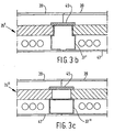
- Figures 3a, 3b and 3c each show a horizontal cross-section 35, 35' and 35" of the frontage construction in accordance with the invention, with a cavity.
- a more rigid post 37 with a wider cross-sectional area can also be employed.
- the posts 37 are hereby only partially enveloped by building elements 39 and have a portion 41 outside the building elements on the inner frontage side.
- the portion 43 enclosed by the building elements has a T-shaped cross-section in this particular embodiment, which portion 43 is provided with ah isolating layer 45 on the outward-facing side.
- An inner wall 47 is located at a distance from the building elements 39. This inner wall can consist of either large plates or smaller stacked plate elements which are affixed to the posts 41.
- the inner wall 47 can also be applied right up against the building elements 39.
- an outer wall can also be applied to the outer portion of the frontage.
- FIGs 4a and 4b show the usage of removable frontispiece panels 49 in the case of the frontage construction in accordance with the invention.
- the inner shells 51 of the building elements 53 are provided with fixing holes 55, within which holes fixing pins 57 present on the panels can be inserted.
- the pins 57 are preferably longer than the depth of the holes 55, whereby the frontispiece panels 49 remain at a distance from the building elements 53 and whereby the thus-formed separation cavity serves as extra isolation means.
- the frontispiece panels or profiled panels 49, 49' and 49" can be mounted in both a horizontal as well as a vertical position, as is depicted in figure 4a and 4b.
- Frontispiece panels can also be affixed to the outer shell 59 of the building elements 53. It is also possible to fix the plates with the aid of hanging means 57'.
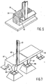
- FIGS 5a and 5b depict a further aspects of the frontage construction in accordance with the invention.
- the frontage construction has similar posts 63 as were employed in the first embodiment.
- the posts 63, 63' can be embodied in a variety of profiles and with various strengths, depending upon the stability criteria and the number of construction layers.
- the posts 63 are situated at a desired mutual separation-distance from each other in such a manner that the building elements which are to be stacked between them fit together accurately with their shells. This desired mutual separation is achieved by coupling the posts 63 by separation elements 65, affixed to the upper and lower ends of the posts 63.
- the separation elements 65 and the posts 63 have positioning means with which they are interconnected at a predetermined distance from each other. These positioning means are on the one hand formed by pins 67 present on the upper and lower ends of the posts 63, and on the other hand by holes 69 situated at predetermined regular intervals in the coupling elements 65. In order to assist in fixation, the pins 67 are provided with external screw-thread to which threaded nuts can be affixed.
- the posts 63 are connected at their upper ends to a wall plate 71 with a steel profile, within which profile slotted holes through which the pins 69 protrude are present, and with which the connection between the wall plate 71 and the posts 63 can also be realised.
- the posts are affixed at their lower ends to a foundation 73.
- this foundation is also dismantable and is formed by a supporting construction consisting of prefabricated stack bearers 75, upon which stack bearers 75 a (preferably steel) profiled foundation beam 77 is fixed, said foundation beam 77 consisting, for example, of a C-profile.
- the foundation beam 77 is also provided with blind holes in order to improve adjustability, through which blind holes the pins 67 protrude, and with which pins the separation elements 65 and the foundation beam 77 are affixed to the posts 63.
- Figure 5b depicts by way of example an embodiment of the frontage construction whereby the posts 63' rest on a prefabricated concrete beam 77' which is placed upon prefabricated stack bearers 75'.
- an edge profile 71' is employed instead of a wall plate 71.
- Figure 5b additionally shows a clamping plate 68 and a foot plate 68' whereby a possibility for adjustment is created.
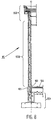
- FIG. 6 shows a foundation 79 with a supporting construction consisting of a prefabricated beam 81 to the side of which a foundation beam 83 in the form of a corner profile has been affixed.
- Figure 7 shows another embodiment whereby separate foundation elements 85 are employed, which elements are fixed to each other at their corner points 87 via coupling elements 89. These foundation elements 85 additionally form a floor for a building using this frontage construction. Corner profiles 91 are affixed to the free sides of these foundation elements 85 and the posts 93 are attached to these profiles. Other foundation constructions such as the fixing of post via a foot plate or an anchor railing are also possible.
- Figure 8 shows by way of example a further embodiment in cross section of a frontage construction 95 containing building elements 959, a foundation 951 and a ceiling construction 953. Building elements are stacked upon the foundation between non-depicted posts (see figure 5). This ceiling construction is subsequently applied.
- Figure 9 shows in more detail the foundation of figure 8.
- the foundation consists of (prefabricated) foundation stack bearers 110. Galvanised steel filling plates 111 are placed upon the foundation stack bearers, which plates ensure accurate termination.
- a (prefabricated) concrete plate 105 is applied on top of the foundation beams, upon which plate the building elements 959 are placed.
- the building elements are provided with a frontispiece wall 102 and a wooden plinth 103. The connection between the frontispiece wall 102 and a deck floor 104 is covered with this wooden plinth.
- the concrete plinth 105 has a number of functions. Because of this concrete plinth, it is possible to allow the building elements 959 to commence above ground-level, with the result that these elements remain cleaner. An adjustment-possibility is also created in this manner. There is also less chance of damage to the building elements as a result of the use of the concrete plinth at ground level.
- An isolation 107 (for example, in the form of steel wool) is applied to the interior of the concrete plinth 105 and is covered with a finishing foil 106.
- isolated channel plate floor sections are located on the inside of the foundation beams 109.
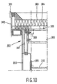
- Figure 10 depicts an embodiment of a ceiling construction 953 from figure 8.
- the building elements 959 are provided with frontispiece walls 309 at their inner sides.
- the uppermost building element is provided with a frontispiece wall at its inner side, to which wall a lowered ceiling 310 is fixed.
- the ceiling construction itself contains fixation means 307 for the fixation of the ceiling construction to the post, the building elements, the roof beams 306 and a tube 308 to form the overhang. Roof plates 305 are fixed to the roof beams. Subsequently, an isolation layer 304 is applied on top of this, which layer is covered in turn with roof coverage 303.
- the roof is further provided with a roof trim and a sideboard 302.
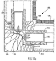
- Figure 11a depicts a corner construction 955 for application in a frontage construction (for example, that of figure 8).
- a corner module 504 connects two building elements 959.
- the corner module is provided with isolation 506 and a foil 505 for covering the foil.
- tubes 503 and plates 502 (of, for example, multiplex), the building elements are interconnected via the corner construction.
- the building elements in turn can be provided with frontispiece walls 508, which walls are finished in the corner with a finishing profile 509.
- Figure 11b depicts coupling parts 111, which can be employed in the frontage construction in accordance with the invention for purposes of interconnecting support beams for the building of several storeys, etc.
Landscapes
- Engineering & Computer Science (AREA)
- Architecture (AREA)
- Civil Engineering (AREA)
- Structural Engineering (AREA)
- Physics & Mathematics (AREA)
- Electromagnetism (AREA)
- Joining Of Building Structures In Genera (AREA)
- Finishing Walls (AREA)
- Building Environments (AREA)
Claims (18)
- Fassadenkonstruktion (1, 35, 35', 35", 61, 95), die vertikale Ständer (3, 37, 63, 63', 93) mit dazwischen gestapelten Bauelementen (9, 39, 53, 959) aufweist, wobei die Elemente zum gegenseitigen Koppeln und zum Koppeln mit den Ständern mit Vertiefungen in ihren Seiten versehen sind, wodurch die Ständer an ihrem unteren Ende mit einem Fundament gekoppelt sind und zumindest teilweise von den Bauelementen umgeben sind, wobei die Elemente einen Kern (11) aus Isolierungsmaterial enthalten und eine Außenschale (13) an einer Hauptseite haben, wobei die Schale an ihrer Ober- und Unterseite mit einem ersten Satz von Profilen versehen ist, wobei die ersten Profile zueinander komplementär sind, und wobei die Bauelemente an ihren linken und rechten Seiten mit einem zweiten Satz komplementärer Profile (31) versehen sind, wobei sich die zweiten Profile (31) zumindest an der Außenschale des Bauelements befindet, dadurch gekennzeichnet, dass die Fassadenkonstruktion Einrichtungen (68, 68') zum Anpassen der Position der Ständer mit Bezug zueinander und zu den Bauelementen aufweist, wobei die Einrichtung eine Klemmplatte (68) und eine Bodenplatte (68') aufweist und wobei die Fassadenkonstruktion ferner einen Sockel (27, 105) unterhalb der Bauelemente aufweist, um die Bauelemente mit Bezug zueinander und mit Bezug zu den Ständern auszurichten.
- Fassadenkonstruktion gemäß Anspruch 1, dadurch gekennzeichnet, dass sich die zweiten Profile zudem zumindest in den Kern hinein erstrecken und zwar an dessen linken und rechten Seiten.
- Fassadenkonstruktion gemäß Anspruch 1 oder 2, dadurch gekennzeichnet, dass die ersten Profile bzw. die zweiten Profile durch eine erste Fase bzw. durch eine zweite Fase ausgebildet sind.
- Fassadenkonstruktion gemäß Anspruch 3, dadurch gekennzeichnet, dass die Fasenebene zumindest der zweiten Fase einen längsgerichteten Knick aufweist.
- Fassadenkonstruktion gemäß Anspruch 4, dadurch gekennzeichnet, dass sich der Knick an der Trennlinie zwischen der Außenschale und dem Kern befindet.
- Fassadenkonstruktion gemäß einem der vorgenannten Ansprüche, dadurch gekennzeichnet, dass die Ständer an ihren der Fassadenaußenseite zugewandten Seitenflächen mit einer Isolierschicht versehen sind.
- Fassadenkonstruktion gemäß einem der vorgenannten Ansprüche, dadurch gekennzeichnet, dass sich ein Abschnitt der Ständer außerhalb der Bauelemente befindet, wobei an diesem Abschnitt eine Wand mit einem Abstand zu den Bauelementen angebracht ist.
- Fassadenkonstruktion gemäß einem der vorgenannten Ansprüche, dadurch gekennzeichnet, dass an den Bauelementen Fassadenbleche abnehmbar angebracht sind.
- Fassadenkonstruktion gemäß Anspruch 8, dadurch gekennzeichnet, dass die Fassadenbleche mit einem Abstand zu den Bauelementen angeordnet sind.
- Fassadenkonstruktion gemäß einem der vorgenannten Ansprüche, dadurch gekennzeichnet, dass die Ständer an ihren oberen und/oder unteren Enden mittels Trennelementen aneinander gekoppelt sind.
- Fassadenkonstruktion gemäß Anspruch 10, dadurch gekennzeichnet, dass die Ständer an ihren oberen Enden an einer Wandplatte befestigt sind und an ihren unteren Enden an einem Fundament befestigt sind.
- Fassadenkonstruktion gemäß Anspruch 11, dadurch gekennzeichnet, dass die Fassadenkonstruktion ein Adapterstück enthält, das sich in einer Aushöhlung zwischen der Schale, dem Kern und dem Fundament befindet und dass sie ein weiteres Adapterstück enthält, das sich in einer weiteren Aushöhlung zwischen der Schale, dem Kern und der Wandplatte befindet.
- Fassadenkonstruktion gemäß einem der Ansprüche 11 oder 12, dadurch gekennzeichnet, dass das Fundament eine Stützstruktur und einen an der Stützstruktur befestigten profilierten Fundamentbalken aufweist.
- Fassadenkonstruktion gemäß Anspruch 13, dadurch gekennzeichnet, dass die Stützstruktur einen vorgefertigten Balken oder vorgefertigte Einzelfundamente enthält.
- Fassadenkonstruktion gemäß Anspruch 13 oder 14, dadurch gekennzeichnet, dass das Fundament getrennte Fundamentelemente und Kopplungselemente enthält, wobei die Kopplungselemente die Fundamentelemente an ihren Ecken miteinander verbinden, und ferner einen profilierten Fundamentbalken enthält, der an den Fundamentelementen befestigt ist.
- Fassadenkonstruktion gemäß Anspruch 13, 14 oder 15, dadurch gekennzeichnet, dass der Fundamentbalken ein an einer Kante der Stützstruktur befestigtes Winkelprofil ist.
- Fassadenkonstruktion gemäß Anspruch 14, 15 oder 16, dadurch gekennzeichnet, dass der Fundamentbalken ein auf der oberen Seite der Stützstruktur liegendes C-Profil ist.
- Gebäude, das mit einer Fassadenkonstruktion gemäß einem der vorangehenden Ansprüche versehen ist.
Applications Claiming Priority (3)
| Application Number | Priority Date | Filing Date | Title |
|---|---|---|---|
| NL9302246A NL9302246A (nl) | 1993-12-23 | 1993-12-23 | Gevelconstructie, alsmede gebouw voorzien van de gevelconstructie en bouwelement toepasbaar in de gevelconstructie. |
| NL9302246 | 1993-12-23 | ||
| PCT/NL1994/000325 WO1995017562A1 (en) | 1993-12-23 | 1994-12-22 | Frontage construction and building equipped with the frontage construction, and building element applicable in the frontage construction |
Publications (2)
| Publication Number | Publication Date |
|---|---|
| EP0796378A1 EP0796378A1 (de) | 1997-09-24 |
| EP0796378B1 true EP0796378B1 (de) | 2003-05-21 |
Family
ID=19863304
Family Applications (1)
| Application Number | Title | Priority Date | Filing Date |
|---|---|---|---|
| EP95904036A Expired - Lifetime EP0796378B1 (de) | 1993-12-23 | 1994-12-22 | Fassadenkonstruktion und mit einer solchen versehenes gebäude sowie in einer solchen fassadenkonstruktion anwendbares bauelement |
Country Status (5)
| Country | Link |
|---|---|
| EP (1) | EP0796378B1 (de) |
| AU (1) | AU1284295A (de) |
| DE (1) | DE69432716D1 (de) |
| NL (1) | NL9302246A (de) |
| WO (1) | WO1995017562A1 (de) |
Families Citing this family (4)
| Publication number | Priority date | Publication date | Assignee | Title |
|---|---|---|---|---|
| NZ533319A (en) * | 2004-07-27 | 2007-03-30 | Craig Wallace Lonsdale | Building system |
| AU2006243830B2 (en) * | 2005-05-04 | 2011-11-03 | Easybuild Australia Pty Ltd | A wall panel, method of construction and attachment system therefor |
| WO2006116823A1 (en) * | 2005-05-04 | 2006-11-09 | Easybuild Australia Pty Ltd | A wall panel, method of construction and attachment system therefor |
| WO2008109917A1 (en) * | 2007-03-09 | 2008-09-18 | D & L Rugari Transport Pty Ltd | Wall structure |
Family Cites Families (3)
| Publication number | Priority date | Publication date | Assignee | Title |
|---|---|---|---|---|
| FR2537629A2 (fr) * | 1982-05-12 | 1984-06-15 | Iotti Construction Monitoring | Procede de fabrication d'elements de cloisons pour batiments |
| FR2601711A1 (fr) * | 1986-07-17 | 1988-01-22 | Roland Lapoudge | Panneaux universels de conception modulaire |
| NL9001513A (nl) * | 1990-07-03 | 1992-02-03 | B O O G B V | Muurelementensysteem. |
-
1993
- 1993-12-23 NL NL9302246A patent/NL9302246A/nl not_active Application Discontinuation
-
1994
- 1994-12-22 WO PCT/NL1994/000325 patent/WO1995017562A1/en not_active Ceased
- 1994-12-22 AU AU12842/95A patent/AU1284295A/en not_active Abandoned
- 1994-12-22 DE DE69432716T patent/DE69432716D1/de not_active Expired - Lifetime
- 1994-12-22 EP EP95904036A patent/EP0796378B1/de not_active Expired - Lifetime
Also Published As
| Publication number | Publication date |
|---|---|
| AU1284295A (en) | 1995-07-10 |
| WO1995017562A1 (en) | 1995-06-29 |
| EP0796378A1 (de) | 1997-09-24 |
| NL9302246A (nl) | 1995-07-17 |
| DE69432716D1 (de) | 2003-06-26 |
Similar Documents
| Publication | Publication Date | Title |
|---|---|---|
| US2091061A (en) | Building construction | |
| ES2459067T3 (es) | Edificio y método de construcción de un edificio | |
| RU2121044C1 (ru) | Строительная панель, способ ее изготовления и созданные на этой основе фундаментный строительный блок, фундамент строения, трехмерная строительная конструкция, высотное здание и трехмерное строение, а также способ крепления деталей архитектурной отделки к поверхности строения | |
| US5865001A (en) | Prefabricated wall panels connecting system | |
| US4158941A (en) | Precast building structure and method of assembly | |
| US3678638A (en) | Building construction of modular units with settable material therebetween | |
| WO2018067067A1 (en) | Prefabricated prefinished volumetric construction module | |
| WO2011144941A2 (en) | Pre-fabricated building structure | |
| EP0485317B1 (de) | Fertigteil-Modularbau | |
| ES2290523T3 (es) | Alineacion vertical y nivelacion de unidades de edificio modulares. | |
| EP0072839B1 (de) | Veränderliche bauwerkskonstruktion | |
| EP0796378B1 (de) | Fassadenkonstruktion und mit einer solchen versehenes gebäude sowie in einer solchen fassadenkonstruktion anwendbares bauelement | |
| US4274242A (en) | Building systems | |
| EP0051592B1 (de) | Gebäude | |
| US7251919B2 (en) | Lightweight building component | |
| FI83120B (fi) | Konstruktionsenhet. | |
| GB2120705A (en) | A method of building a house starting from a packaged structure | |
| EP0090473A1 (de) | Gebäude, Wandelemente und Profile für dieselben | |
| US20080155937A1 (en) | Method for Building Houses | |
| EP3798388A1 (de) | Wiederaufbaubares wohnhaussystem mit interner stützstruktur | |
| DE102017005417B4 (de) | Hausbauschablone sowie hierfür geeignetes Fassadenmodul | |
| PL143356B1 (en) | Building unit for erection of basic load carrying and siding building structures | |
| GB2062059A (en) | Method and means for building an insulating wall | |
| EP4509668A1 (de) | Bauwerk aus einem satz vorgefertigter betonelemente | |
| AU593917B2 (en) | Building systems |
Legal Events
| Date | Code | Title | Description |
|---|---|---|---|
| PUAI | Public reference made under article 153(3) epc to a published international application that has entered the european phase |
Free format text: ORIGINAL CODE: 0009012 |
|
| 17P | Request for examination filed |
Effective date: 19961001 |
|
| AK | Designated contracting states |
Kind code of ref document: A1 Designated state(s): BE DE FR GB LU NL |
|
| RAP1 | Party data changed (applicant data changed or rights of an application transferred) |
Owner name: AXALL B.V. |
|
| 17Q | First examination report despatched |
Effective date: 19990913 |
|
| GRAH | Despatch of communication of intention to grant a patent |
Free format text: ORIGINAL CODE: EPIDOS IGRA |
|
| GRAH | Despatch of communication of intention to grant a patent |
Free format text: ORIGINAL CODE: EPIDOS IGRA |
|
| GRAA | (expected) grant |
Free format text: ORIGINAL CODE: 0009210 |
|
| AK | Designated contracting states |
Designated state(s): BE DE FR GB LU NL |
|
| PG25 | Lapsed in a contracting state [announced via postgrant information from national office to epo] |
Ref country code: FR Free format text: LAPSE BECAUSE OF FAILURE TO SUBMIT A TRANSLATION OF THE DESCRIPTION OR TO PAY THE FEE WITHIN THE PRESCRIBED TIME-LIMIT Effective date: 20030521 Ref country code: BE Free format text: LAPSE BECAUSE OF FAILURE TO SUBMIT A TRANSLATION OF THE DESCRIPTION OR TO PAY THE FEE WITHIN THE PRESCRIBED TIME-LIMIT Effective date: 20030521 |
|
| REG | Reference to a national code |
Ref country code: GB Ref legal event code: FG4D |
|
| REF | Corresponds to: |
Ref document number: 69432716 Country of ref document: DE Date of ref document: 20030626 Kind code of ref document: P |
|
| PG25 | Lapsed in a contracting state [announced via postgrant information from national office to epo] |
Ref country code: DE Free format text: LAPSE BECAUSE OF FAILURE TO SUBMIT A TRANSLATION OF THE DESCRIPTION OR TO PAY THE FEE WITHIN THE PRESCRIBED TIME-LIMIT Effective date: 20030822 |
|
| PG25 | Lapsed in a contracting state [announced via postgrant information from national office to epo] |
Ref country code: LU Free format text: LAPSE BECAUSE OF NON-PAYMENT OF DUE FEES Effective date: 20031222 Ref country code: GB Free format text: LAPSE BECAUSE OF NON-PAYMENT OF DUE FEES Effective date: 20031222 |
|
| PLBE | No opposition filed within time limit |
Free format text: ORIGINAL CODE: 0009261 |
|
| STAA | Information on the status of an ep patent application or granted ep patent |
Free format text: STATUS: NO OPPOSITION FILED WITHIN TIME LIMIT |
|
| 26N | No opposition filed |
Effective date: 20040224 |
|
| EN | Fr: translation not filed | ||
| GBPC | Gb: european patent ceased through non-payment of renewal fee |
Effective date: 20031222 |
|
| PGFP | Annual fee paid to national office [announced via postgrant information from national office to epo] |
Ref country code: NL Payment date: 20051223 Year of fee payment: 12 |
|
| PG25 | Lapsed in a contracting state [announced via postgrant information from national office to epo] |
Ref country code: NL Free format text: LAPSE BECAUSE OF NON-PAYMENT OF DUE FEES Effective date: 20070701 |
|
| NLV4 | Nl: lapsed or anulled due to non-payment of the annual fee |
Effective date: 20070701 |