EP0796129B1 - Herzschrittmacher mit sinus-präferenz verfahren - Google Patents
Herzschrittmacher mit sinus-präferenz verfahren Download PDFInfo
- Publication number
- EP0796129B1 EP0796129B1 EP95939989A EP95939989A EP0796129B1 EP 0796129 B1 EP0796129 B1 EP 0796129B1 EP 95939989 A EP95939989 A EP 95939989A EP 95939989 A EP95939989 A EP 95939989A EP 0796129 B1 EP0796129 B1 EP 0796129B1
- Authority
- EP
- European Patent Office
- Prior art keywords
- atrial
- pacing
- escape interval
- interval
- ventricular
- Prior art date
- Legal status (The legal status is an assumption and is not a legal conclusion. Google has not performed a legal analysis and makes no representation as to the accuracy of the status listed.)
- Expired - Lifetime
Links
Images


Classifications
-
- A—HUMAN NECESSITIES
- A61—MEDICAL OR VETERINARY SCIENCE; HYGIENE
- A61N—ELECTROTHERAPY; MAGNETOTHERAPY; RADIATION THERAPY; ULTRASOUND THERAPY
- A61N1/00—Electrotherapy; Circuits therefor
- A61N1/18—Applying electric currents by contact electrodes
- A61N1/32—Applying electric currents by contact electrodes alternating or intermittent currents
- A61N1/36—Applying electric currents by contact electrodes alternating or intermittent currents for stimulation
- A61N1/362—Heart stimulators
- A61N1/365—Heart stimulators controlled by a physiological parameter, e.g. heart potential
- A61N1/368—Heart stimulators controlled by a physiological parameter, e.g. heart potential comprising more than one electrode co-operating with different heart regions
-
- A—HUMAN NECESSITIES
- A61—MEDICAL OR VETERINARY SCIENCE; HYGIENE
- A61N—ELECTROTHERAPY; MAGNETOTHERAPY; RADIATION THERAPY; ULTRASOUND THERAPY
- A61N1/00—Electrotherapy; Circuits therefor
- A61N1/18—Applying electric currents by contact electrodes
- A61N1/32—Applying electric currents by contact electrodes alternating or intermittent currents
- A61N1/36—Applying electric currents by contact electrodes alternating or intermittent currents for stimulation
- A61N1/362—Heart stimulators
- A61N1/365—Heart stimulators controlled by a physiological parameter, e.g. heart potential
- A61N1/36585—Heart stimulators controlled by a physiological parameter, e.g. heart potential controlled by two or more physical parameters
Definitions
- the present invention relates to dual chamber, rate-responsive pacemakers.
- Dual chamber pacing modes have been widely adopted for pacing therapy.
- the dual chamber operating modes is the "DDD” mode, which can pace an atrium and a ventricle, senses both the atrium and the ventricle, and can either inhibit or trigger pacing stimuli for both chambers.
- This mode has a sensor augmented variant mode called "DDDR", where the "R” stands for rate-adaptive or rate modulation.
- a DDD pacemaker includes an atrial sense amplifier to detect atrial depolarizations of the heart, and a ventricular sense amplifier to detect ventricular depolarizations of the heart. If the atrium of the heart fails to beat within a predefined time interval (atrial escape interval), the pacemaker supplies an atrial stimulus to the atrium through an appropriate lead system. Following an atrial event (either sensed or paced) and an atrioventricular (A-V) interval, the pacemaker supplies a ventricular pacing stimulus to the ventricle through an appropriate lead system, if the ventricle fails to depolarize on its own. Pacemakers which perform this function have the capability of tracking the patient's natural sinus rhythm and preserving the hemodynamic contribution of the atrial contraction over a wide range of heart rates.
- SA sinoatrial
- DDD Downlink Defined Defined Defined Defined Defined Defined Defined Defined Defined Defined Defined Defined Defined Defined Defined Defined Defined Defined Defined Defined Defined Defined Defined Defined Defined Defined Defined Defined Defined Defined Defined Defined Defined Define AV conduction.
- SSS Sick Sinus Syndrome
- the DDDR mode provides some relief by pacing the atria and ventricles at a sensor rate determined by a sensor which senses a physiological indicator of the patients' metabolic needs.
- sensor rates are sometimes too high and sometimes too low for a variety of reasons, including, errors related to the input of programmable parameters, limitations of the sensor's ability to accurately sense the physical quantity being sensed, and limitations or problems with the algorithm used to determine the sensor rate.
- pacemakers operating in prior art sensor driven pacing modes pace at the sensor rate (and overdrive the atrium) whenever the sensor rate exceeds the sinus rate, even when the sinus rate is actually appropriate, and even when the difference between the two rates is too small to provide any discernible benefit in pacing at the higher sensor rate. Inappropriate sensor rate pacing can lead to unnecessary overdrive of the atrium, and unwarranted expenditure of battery energy.
- a DDDR pacemaker wherein the operating or pacing mode is switched between the DDD, DDIR and WIR modes as a function of the difference between the Average Atrial Rate (AAR) and the Average Combined Sensor Rate (ACSR).
- the DDD pacing mode (which is not a sensor driven pacing mode) is preferred as long as the AAR and ACSR are within a user selected range, and the AAR does not exceed the Atrial Upper Rate Limit (AURL) or is not irregular at higher rates.
- the WIR mode is preferred to avoid inappropriate atrial tracking, atrial competitive pacing and risk of inducing more atrial arrhythmias.
- the atrial rate is not adequate, so the DDIR mode is preferred.
- the rise up and fall back pacing rates are smoothed by taking place over several heart beats or a predetermined time interval during mode switch transitions.
- the mode switching depends on the comparison of the AAR and ACSR up to the AURL and the Sensor Upper Rate Limit (SURL). Generally, when the AAR is within a first range exceeding the ACSR and both are below the AURL and the SURL, DDD pacing is maintained. When the AAR rises out of that range, then the mode is switched to VVIR. Similarly, when the ACSR is within a second range exceeding the AAR, DDD pacing is also maintained. When the second range is exceeded by the ACSR, the mode is switched to DDIR.
- SURL Sensor Upper Rate Limit
- the pacing rate is limited by the SURL, and the mode is switched to DDD when the Instantaneous Atrial Rate (IAR) equals the ACSR.
- IAR Instantaneous Atrial Rate
- the pacing rate is limited to the AURL, and the mode is switched to VVIR when the ACSR falls below the SURL while the AAR remains above the AURL.
- the first and second ranges are derived as functions f(A-S) and f(S-A) of the AAR and ACSR between the minimum rate and the AURL and SURL and are programmable by the physician.
- the actual instantaneous ranges vary as a function of the current AAR and ACSR values.
- the '949 patent emphasizes the desirability of maintaining DDD pacing at an atrial escape or A-A escape interval derived from the AAR whenever possible. That is, the DDD mode is forced and departed from only under the conditions described above.
- the instantaneous pacing escape interval/rate are determined by the measured intervals between atrial events used to formulate the AAR while in the DDD operating mode.
- the ACSR is also derived independently and only resorted to to set the pacing escape interval/rate in the modes where atrial synchrony is departed from under the above described conditions.
- a rate-responsive pacemaker with automatic mode switching and/or variable hysteresis rate is described.
- a physiological, activity related, sensor develops a physiologic escape interval/rate between a minimum and a maximum rate limit (SURL) as shown in Figure 3A thereof.
- a variable hysteresis escape interval setting a hysteresis rate below the physiologic rate is defined as shown in Figures 3B and 4 thereof.
- rate-responsive mode e.g. VVIR mode, if the prevailing V-V escape interval times out and a V-PACE pulse is delivered, then the physiologic escape interval is employed as the next V-V escape interval.
- variable hysteresis escape interval is used as the next escape V-V interval. Use of the variable escape interval continues up to the maximum rate which is the SURL less the maximum hysteresis rate increment as shown in Figure 3B.
- the '523 patent emphasizes the importance of switching the pacing mode from the prevailing dual chamber pacing mode to a single chamber mode (typically VVIR) at high pacing rates because the contribution of the atria to cardiac output diminishes at high heart contraction rates while the energy consumption demanded by dual chamber pacing increases.
- V-A interval is selected to be either the physiologic escape interval, or the hysteresis interval depending on whether or not a V-SENSE event is detected in the A-V interval.
- the mode is preferably switched to the VVIR mode.
- a dual chamber, rate-responsive pacemaker which correlates the atrial upper rate limit, designated HSR in this patent, to the sensor rate designated KA to allow upper rate tracking to vary with the physiologic sensor rate.
- US Patent No. 5,374,281 issued to Kristall and Duncan provides a means to allow programmable hysteresis to automatically extend an escape interval to allow for some sinus rate following in a sensor rate responsive pacer.
- US 5,237,992 discloses an implantable pacemaker providing hysteresis in dual-chamber modes.
- the pacemaker defines a basic atrial escape interval (AEI) that defines the maximum time between a ventricular event and a subsequent atrial event, as well as an A-V delay (AVD) that defines the maximum time between an atrial event and the next ventricular event.
- AEI basic atrial escape interval
- A-V delay A-V delay
- the sum of AEI plus AVD thus sets the rate at which stimulation pulses are generated in the absence of sensed natural cardiac activity.
- a first type of hysteresis, atrial escape rate hysteresis causes the AEI to be extended upon sensing natural atrial beats (P-waves).
- a stimulation pulse is generated and the AEI reverts to its initial value.
- a second type of hysteresis atrial-induced AV delay hysteresis, extends the next AVD and shortens the AEI in response to sensing a P-wave, thereby keeping the pacemaker's programmed rate the same.
- a third type of hysteresis ventricular-induced AV delay hysteresis, extends the next AVD and shortens the AEI in response to sensing an R-wave. Any desired combination of the three types of hysteresis may be programmably selected for use within the pacemaker.
- EP-A-0574127 discloses a DDD pacemaker which uses hysteresis to maximise the number of normally conducted ventricular beats with an optimum A-V delay for paced ventricular beats.
- the pacer includes means for adjusting the A-V delay period to enhance the probability of detecting naturally occurring ventricular depolarization signals when such signals are being detected at a predetermined rate and switching to a more hemodynamically appropriate A-V delay period when paced beats predominate.
- the invention is implemented in software run on a microprogrammable controller comprising the DDD pacemaker.
- a dual chamber, rate-responsive pacemaker pulse generator adapted to be attached with atrial and ventricular pacing and sensing electrodes and comprising atrial and ventricular sense amplifiers for sensing natural atrial and ventricular depolarizations as atrial and ventricular sensed events, respectively, and atrial and ventricular pulse generators for providing atrial and ventricular pacing pulses to the patient's atrium and ventricle, respectively, at an adjustable pacing rate dependent on the patient's natural atrial depolarization rate and upon the patient's physiologic needs for cardiac output, said pacemaker further comprising:
- the present invention thus operates a dual chamber, rate responsive pacemaker preferentially in the DDDR mode at a physiologic sensor derived V-A escape interval while allowing an atrial sinus tracking function to be followed on a beat-to-beat basis in patients having reasonable chronotropic competence when the underlying sinus rate is appropriate to the sensor derived rate.
- the rate responsive pacemaker is preferably a dual chamber, rate-responsive pacemaker pulse generator adapted to be attached with atrial and ventricular pacing and sensing electrodes and comprising atrial and ventricular sense amplifiers for sensing natural atrial and ventricular depolarizations as atrial and ventricular sensed events, respectively, and atrial and ventricular pulse generators for providing atrial and ventricular pacing pulses to the patient's atrium and ventricle, respectively, at an adjustable pacing rate dependent on the patient's natural atrial depolarization rate and upon the patient's physiologic needs for cardiac output, wherein the pacemaker includes in means for:
- the apparatus of the present invention further comprise the means for periodically searching for an underlying sinus rhythm of the heart chamber by periodically adding the incremental interval (sinus preference window) to the sensor-derived escape interval to determine if a depolarization will be sensed, and, if present, retaining the prolonged escape interval as long as the sinus depolarizations are sensed.
- the apparatus further comprises the means for and steps of measuring the elapsed time during the prolonged escape intervals until the sensing of a depolarization occurs, and, if the sensed depolarization is measured within the sensor-derived escape interval, adding the incremental interval to the measured escape interval rather than the sensor-derived escape interval in setting the succeeding prolonged escape interval.
- the apparatus comprises the means for adding the full incremental interval to the measured escape interval or the sensor-derived escape interval in setting the succeeding prolonged escape interval in all cases where the depolarization is sensed in a preceding prolonged escape interval with a decremented duration, incremental interval.
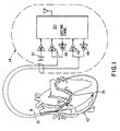
- Figure 1 is block level diagram of a DDDR pacemaker capable of implementing the Sinus Preference Algorithm of the present invention.
- Figure 2 is a timing diagram depicting Sinus Preference Windows of the present invention in response to atrial paced and sensed events
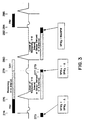
- Figure 3 is a continuation of the timing diagram in Figure 2.
- Figure 4 is a graph of heart rate versus time using the Sinus Preference Algorithm of the present invention.
- Figure 5 is a resulting electrocardiogram in response to changing Sinus Preference Windows and the occurrence of atrial sensed events.
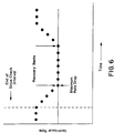
- Figure 6 is a graph of ventricular rate versus time, illustrating several recovery beats after the maximum rate drop has been reached.
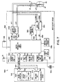
- Figure 7 is a block diagram of the dual chamber pacemaker illustrated in Figure 1, illustrating the logic and timing components in more detail.
- FIG. 8 is a flowchart of the overall operation of the pacemaker of Figure 7.
- Figures 9 and 10 are a combined flowchart of the Sinus Preference Algorithm of the present invention that may be implemented in the pacemaker of Figures 1 and 7 in conjunction with the overall function of the flowchart of Figure 8.
- the present invention may be incorporated into such prior art pacemakers as, for example, DDD pacemaker taught by U.S. Patent 4,312,355 to Funke.
- Another rate-responsive pacemaker suitable for use with the invention is taught in U.S. Patent 4,951,667 to Markowitz et.al., which teaches a dual chamber, activity-based, rate-responsive pacemaker of the DDDR type. This pacemaker utilizes sensed patient activity to set the pacemaker's "sensor" rate.
- the present invention is preferably implemented in multi-programmable pacemaker of a type known in the prior art
- FIG. 1 is block level diagram which sets forth the structures required to incorporate the invention into a DDD/DDDR pacemaker.
- the patient's heart 10 has an atrial pacing lead 12 passed into the right atrium and a ventricular lead 9 passed into the right ventricle.
- the atrial lead 12 has an atrial electrode array 13 which couples the pacemaker 14 to the atrium.
- the ventricular lead 9 has a ventricular electrode array 15 for coupling the pacemaker 14 to the ventricular tissue of a patient's heart 10.
- the atrial electrode array 13 is coupled to both an atrial pace stimulus generator 16 (APG), and an atrial sense amplifier 17 (ASA).
- APG atrial pace stimulus generator
- ASA atrial sense amplifier 17
- VPG ventricular pace stimulus generator 18
- VSA ventricular sense amplifier 19
- Figure 1 shows a preferred patient activity sensor (PAS) 21 and appropriate signal conditioning circuitry, which can be provided to alter the pacemaker operation in response to the sensed motion of the patient.
- PAS patient activity sensor
- An appropriate activity-based, rate-responsive system is taught by U.S. Patent 4,428,378 to Anderson et al. It should be appreciated that alternative sensors of a physiologic parameter indicative of physiologic demand on a patient's heart can be provided to achieve rate and post-ventricular atrial refractory period (PVARP) variation based upon other sensed physical parameters.
- PVARP post-ventricular atrial refractory period
- the atrial sense amplifier ASA 17 detects depolarizations of atrial tissue and generates an atrial sensed event (ASE) to indicate the detection of an atrial beat of the patient's heart.
- the ventricular sense amplifier VSA 19 responds to a ventricular beat of the patient's heart and generates a corresponding ventricular sensed event (VSE).
- the pacemaker logic 20 which is coupled to the sense amplifiers, generates various time intervals in response to detected atrial and ventricular sensed events, and generates both atrial paced event (APE) and ventricular paced event (VPE) signals in response to timer logic and the sense amplifier signals.
- APE atrial paced event
- VPE ventricular paced event
- timer logic 20 is provided with means to time out a programmed A-V delay period (AVD).
- the A-V delay period is initiated by the occurrence of either an atrial sensed or atrial paced event.
- the A-V delay period may end with the generation of a ventricular paced event (VPE) or on sensing a ventricular sensed event (VSE).
- Logic and timing circuit 20 also provides for a programmed post-ventricular atrial refractory period (PPVARP).
- the PPVARP period begins with either a ventricular paced event (VPE) or a ventricular sensed event (VSE), and expires at the conclusion of a physician-set time interval.
- Logic and timing circuit 20 similarly defines a ventricular refractory period (VRP) following either a VSE or VPE, which is typically shorter than the portion of the PPVARP following a VSE or VPE. In the case of an ectopic VSE, both a VRP and a PPVARP may be generated.
- Logic and timing circuit 20 also defines an atrial refractory period (ARP) following either a ASE or APE.
- ARP atrial refractory period
- the logic 20 also times out a refractory limit interval (RLI) which begins with the occurrence of a ventricular sensed or paced event.
- RLI refractory limit interval
- Pacemaker logic 20 also times out a disable interval period T of a fixed but physician-selected duration. This disable interval time period begins upon the occurrence of a VPE in a pacing cycle where the next post-ventricular atrial refractory period is extended.
- digital pacemaker logic and timing circuit 20 defines an atrial blanking interval following delivery of an APE pulse, during which atrial sensing is disabled, as well as ventricular blanking intervals following atrial and ventricular pacing pulse delivery, during which ventricular sensing is disabled.
- Pacemaker logic 20 also times out an upper rate limit interval (URL). This timer is initiated by the occurrence of a VPE or VSE, and limits the upper rate at which ventricular stimuli are delivered to the heart.
- URL upper rate limit interval
- Preferably two separate lower rate V-A interval timer functions are provided.
- the first is set by the physician when the base pacing rate is selected.
- This DDD V-A time interval starts from the occurrence of a VSE or VPE, and provided neither an ASE nor a VSE occurs during the V-A time interval, an APE is generated after the expiration of the V-A time interval.
- the duration of the second lower rate time interval is a function of the measured patient activity acquired by the activity sensor 21.
- this DDDR V-A time interval begins with a sensed or paced ventricular event (VSE or VPE, respectively) and has a time duration reflecting patient activity.
- VSE or VPE paced ventricular event
- the pacemaker logic 20 is also coupled to paced event pulse generators 16 and 18.
- atrial paced event signals are coupled to the atrial pace stimulus generator 16 to produce an atrial pacing stimulus while the ventricular paced event signal generates a ventricular pacing stimulus through the ventricular pace stimulus pulse generator 18.
- Pacemaker logic 20 thus defines the basic pacing or escape interval over a pacing cycle, which corresponds to a successive A-V interval and V-A interval.
- the IPG circuit 300 of Figure 7 is divided generally into a microcomputer circuit 302 and a pacing circuit 320.
- the pacing circuit 320 includes the ASA 17 and VSA 19 of Figure 1 as the output amplifier circuit 340 and the APG 16 and the VPG 18 in the sense amplifiers 360.
- the output circuit 340 and sense amplifier circuit 360 may contain pulse generators and sense amplifiers corresponding to any of those presently employed in commercially marketed cardiac pacemakers.
- the bipolar leads 9 and 12 are illustrated schematically as coupled directly to the input/output circuit 320. However, in the actual implantable device they would, of course, be coupled by means of removable electrical connectors inserted in the connector block illustrated in broken lines 14 in Figure 1.
- Sensed atrial depolarizations or P-waves that are confirmed by the atrial sense amplifier (ASE) in response to an A-sense are communicated to the digital controller/timer circuit 330 on ASE line 352.
- ventricular depolarizations or R-waves that are confirmed by the ventricular sense amplifier in response to a V-sense are communicated to the digital controller/timer circuit 330 on VSE line 354.
- digital controller/timer circuit 330 In order to trigger generation of a ventricular pacing or VPE pulse, digital controller/timer circuit 330 generates a trigger signal on V-trig line 342. Similarly, in order to trigger an atrial pacing or APE pulse, digital controller/timer circuit 330 generates a trigger pulse on A-trig line 344.
- Crystal oscillator circuit 338 provides the basic timing clock for the pacing circuit 320, while battery 318 provides power.
- Power-on-reset circuit 336 responds to initial connection of the circuit to the battery for defining an initial operating condition and similarly, resets the operative state of the device in response to detection of a low battery condition.
- Reference mode circuit 326 generates stable voltage reference and currents for the analog circuits within the pacing circuit 320, while analog to digital converter ADC and multiplexor circuit 328 digitizes analog signals and voltage to provide real time telemetry of a cardiac signal from sense amplifier 360, for uplink transmission via RF transmitter and receiver circuit 332.
- Voltage reference and bias circuit 326, ADC and multiplexor 328, power-on-reset circuit 336 and crystal oscillator circuit 338 may correspond to any of those presently used in currently marketed implantable cardiac pacemakers.
- Data transmission to and from the external programmer 40 illustrated in Figure 2 is accomplished by means of the telemetry antenna 334 and an associated RF transmitter and receiver 322, which serves both to demodulate received downlink telemetry and to transmit uplink telemetry.
- circuitry for demodulating and decoding downlink telemetry may correspond to that disclosed in U.S. Patent No. 4,556,063 issued to Thompson et al. and U.S. Patent No. 4,257,423 issued to McDonald et al., while uplink telemetry functions may be provided according to U.S. Patent No. 5,127,404 issued to Wyborny et al. and U.S. Patent No. 4,374,382 issued to Markowitz.
- Uplink telemetry capabilities will typically include the ability to transmit stored digital information as well as real time or stored EGMs of atrial and/or ventricular electrical activity (according to the teaching of the above-cited Wyborny patent), as well as transmission of Marker Channel pulses indicating the occurrence of sensed and paced depolarizations in the atrium and ventricle, as disclosed in the cited '382 Markowitz patent.
- Control of timing and other functions within the pacing circuit 320 is provided by digital controller/timer circuit 330 included in logic and timing block 20 of Figure 1, which includes a set of timers and associated logic circuits connected with the microcomputer 302.
- Microcomputer 302 controls the operational functions of digital controller/timer 324, specifying which timing intervals are employed, and controlling the duration of the various timing intervals of Table 1, via data and control bus 306.
- Microcomputer 302 contains a microprocessor 304 and associated system clock 308 and on-processor RAM and ROM chips 310 and 312, respectively.
- microcomputer circuit 302 includes a separate RAM/ROM chip 314 to provide additional memory capacity.
- Microprocessor 304 is interrupt driven, operating in a reduced power consumption mode normally, and awakened in response to defined interrupt events, which may include the A-trig, V-trig, ASE and VSE signals.
- defined interrupt events which may include the A-trig, V-trig, ASE and VSE signals.
- the specific values of the intervals defined are controlled by the microcomputer circuit 302 by means of data and control bus 306 from programmed-in parameter values and operating modes.
- the IPG is programmed to a rate responsive mode
- the patient's activity level is monitored periodically, and the sensor derived V-A escape interval is adjusted proportionally.
- a timed interrupt e.g. every two seconds, may be provided in order to allow the microprocessor 304 to analyze the output of the activity circuit (PAS) 322 and update the basic V-A escape interval employed in the pacing cycle.
- the microprocessor 304 may also define variable A-V intervals and variable ARPs and VRPs which vary with the V-A escape interval established in response to patient activity.
- Digital controller/timer circuit 330 thus defines the basic pacing or escape interval over a pacing cycle which corresponds to a successive A-V interval and V-A interval.
- digital controller/timer circuit 330 defines the A-V delay intervals as an SAV that commences following a sensed ASE and a PAV that commences following a delivered APE, respectively.
- Digital controller/timer circuit 330 also starts and times out the intervals set forth above in Table 1 for controlling operation of the ASA and VSA in sense amplifier circuit 360 and the APG and VPG in output amplifier circuit 340.
- digital controller/timer circuit 330 defines an atrial blanking interval following delivery of an APE pulse, during which atrial sensing is disabled, as well as ventricular blanking intervals following atrial and ventricular pacing pulse delivery, during which ventricular sensing is disabled.
- Digital controller/timer circuit 330 also defines the ARP during which atrial sensing is disabled or the ASE is ignored for the purpose of resetting the V-A escape interval.
- the ARP extends from the beginning of the SAV or PAV interval following either an ASE or an A-trig and until a predetermined time following sensing of a ventricular depolarization or triggering the delivery of a VPE pulse.
- the durations of the ARP, PVARP and VRP may also be selected as a programmable parameter stored in the microcomputer 302.
- Digital controller/timer circuit 330 also controls sensitivity settings of the sense amplifiers 360 by means of sensitivity control 350.
- the illustrated IPG block diagram of Figure 7 is merely exemplary, and corresponds to the general functional organization of most multi-programmable microprocessor controlled DDD(R) cardiac pacemakers presently commercially available. It is believed that the present invention is most readily practiced in the context of such a device, and that the present invention can therefore readily be practiced using the basic hardware of existing microprocessor controlled dual chamber pacemakers, as presently available, with the invention implemented primarily by means of modifications to the software stored in the ROM 312 of the microcomputer circuit 302.
- the present invention may also be usefully practiced by means of a full custom integrated circuit, for example, a circuit taking the form of a state machine, in which a state counter serves to control an arithmetic logic unit to perform calculations according to a prescribed sequence of counter controlled steps.
- a full custom integrated circuit for example, a circuit taking the form of a state machine, in which a state counter serves to control an arithmetic logic unit to perform calculations according to a prescribed sequence of counter controlled steps.
- the present invention should not be understood to be limited to a pacemaker having an architecture as illustrated in Figure 1 or 7, and a circuit architecture as illustrated in Figure 1 or 7 is not believed to be a prerequisite to enjoying the benefits of the present invention.
- FIG 8 is a functional flow chart of the overall pacing cycle timing operation of the pacemaker illustrated in Figures 1 and 7 in DDDR pacing mode.
- functional steps corresponding to the provision of the ARP, VRP, PPVARP, blanking periods and delivery of VPE and VSE have been omitted, to allow for easier understanding of the overall timing operations.
- the basic pacing cycle timing of the pacemaker is based on the definition of a sensor-derived V-A escape interval (SVA) and may reflect the Sinus Preference Window (SPW) in a manner further set forth in the flowchart of Figures 9 and 10 described below.
- SVA sensor-derived V-A escape interval
- SPW Sinus Preference Window
- the V-A interval is first reset in response to an ASE or APE, and timing of the current A-V delay interval (AVD) is commenced.
- A-V delay interval the system awaits either time out of the current A-V delay interval (PAV or SAV) at block 402 or ventricular sensing at block 406. If a VSE does not occur at block 406 prior to A-V delay interval time out, a VPE is generated at block 404 at the end of the A-V interval.
- the pacemaker's timing may be reset at block 408 to select a V-A escape interval, which is either the sensor-derived V-A escape interval or the prolonged V-A escape interval defined in the manner shown in the flowchart of Figures 9 and 10 described below. Then the selected V-A delay interval is timed out at block 410.
- the algorithm awaits expiration of the V-A escape interval at block 412. If the V-A escape interval expires at block 412 without any intervening ASE or VSE sensing, an APE pulse is generated at block 414. The next succeeding A-V delay interval is defined to be equal to PAV at block 416, and the A-V timing is commenced again at block 400.
- Sensing of a VSE at block 418 outside of the VRP causes the V-A interval timing to be reset in block 420 and the reset V-A interval to be restarted in block 412.
- a VSE sensed at this point is not effective to trigger an update of the SAV and PAV intervals.
- the V-A interval is measured and stored in block 424.
- the current sensor-derived V-A escape interval is a prolonged V-A escape interval selected in any of the ways to include all or part of a SPW, the measured V-A interval may be longer than the sensor-derived V-A escape interval.
- next V-A escape interval may be derived from the measured V-A interval in block 428 and used in block 408 during the next pacing cycle.
- the next A-V delay interval is set to SAV in block 426, and the A-V interval is restarted in block 400.
- time interval values for the parameters of Table 1 employed in the algorithm of Figure 8 and any other time intervals defined by operating algorithms at any particular time are stored in either ROM or RAM and are fetched and used as described above.
- the specified time intervals may be fetched and employed in each designated step in response to the trigger or event signals designated in any of the algorithms.
- a pacemaker employing the Sinus Preference Algorithm of the present invention tracks the sinus rate when the sinus rate exceeds the sensor rate.
- the Sinus Preference Algorithm does not always cause the pacemaker to pace at the end of the sensor derived escape interval whenever the sensor rate exceeds the sinus rate.
- the pacemaker 14 paces at the sensor rate, or a variation thereof, whenever the sensor rate exceeds the sinus rate by more than a programmable maximum rate drop. Otherwise, the pacemaker 14. tracks the sinus rate.
- the Sinus Preference Algorithm will be explained in greater detail infra., with reference to Figures 2-6 and in reference to the combined flowchart of Figures 9 and 10.
- FIGS 2 and 3 together, represent a timing diagram of an example of successive heart cycles which illustrate certain of the operations of the Sinus Preference Algorithm of the present invention in the context of the pacemaker of Figures 1, 7 and 8.
- VPE ventricular paced event
- APE atrial paced event
- PAV paced atrioventricular
- the atrial pulse generator 16 of the pacemaker 14 (output amplifier circuit 340 of Figure 7) again delivers a pacing stimulus APE to the atrium at point 254, thereby completing a pacing cycle commencing from the point 250.
- a measured V-A interval (MVA) as shown, for example, between points 256 and 258.
- the VPG 18 of pacemaker 14 delivers a pacing stimulus signal VPE to the ventricle.
- VPE a pacing stimulus signal
- an ASE occurs at point 258, and a measured V-A interval (less than the sensor-derived physiologic V-A interval in this instance) is derived and is followed by a sensed atrioventricular (SAV) interval and a VPE at point 260.
- SAV sensed atrioventricular
- the occurrence of the first ASE at point 258 causes the algorithm to redefine the next atrial escape V-A interval.
- the previous measured V-A interval is compared to the sensor-derived V-A interval. If the sensor-derived V-A interval (SVA) is the lesser of the two (which can occur as shown later if the previous V-A interval is prolonged by a SPW interval), the new V-A interval is set equal to the sensor-derived V-A interval plus the current SPW (in this instance, MaxSPW).
- the algorithm compares the sum of the previous measured V-A interval plus the previous SPW with the sensor-derived V-A interval. The greater of the two is chosen as the new V-A escape interval to be timed from point 260. In this case, there is no prior SPW, and so the first Sinus Preference Window SPW 1 is set to correspond to the programmed maximum rate drop (MaxSPW) from the sensor rate allowable.
- MaxSPW programmed maximum rate drop
- the Sinus Preference Algorithm operates within the microcomputer 302 and digital controller /timer circuit 330 and endeavors to first pace at the sensor rate minus the maximum rate drop (inversely corresponding to the MaxSPW) in response to a spontaneous ASE to look for further possible ASEs, thus searching for sinus node beats occurring within acceptable proximity to the sensor rate. If found, the Sinus Preference Algorithm operates pacemaker 14 to track the sinus rate. However, if none are found or if they discontinue as shown, for example, at point 270, the pacing rate remains at the maximum rate drop level for several programmable recovery beats, e.g. the six pacing cycles at the maximum rate drop as shown in Figure 6.
- a second ASE occurs prior to the expiration of the prolonged V-A escape interval and within the SPW 1 .
- the next Sinus Preference Window SPW 2 remains at MaxSPW, and the new prolonged V-A escape interval is chosen as described supra by adding the sensor-derived V-A interval with MaxSPW. Since no ASE occurs during the atrial escape interval, an APE occurs at its expiration followed in time by a VPE .
- FIG 3 it illustrates an operation of the Sinus Preference Algorithm in conjunction with the gradual rate increase from the maximum rate drop and back to the sensor-derived rate after delivery of the recovery beats.
- the pacing rate (as defined by the V-A escape interval) is increased by a programmable "SPW Rate Change".
- SPW Rate Change From the SPW Rate Change, a corresponding delta is derived, where delta equals the inverse of SPW Rate Change, or the change in interval needed to accomplish the desired rate change.
- the delta is subtracted from each succeeding SPW as shown at points 274 and 278 in Figure 3 so that the pacing rate begins to increment by the SPW Rate Change.
- SPW 3 equals SPW 2 minus delta
- SPW 4 equals SPW 3 minus delta.
- Figure 3 also illustrates the situation that may occur where, prior to the expiration of the atrial escape interval that includes SPW 4 , an ASE occurs, which resets SPW 5 to MaxSPW.
- the measured V-A escape interval is longer than the sensor-derived or physiologic V-A escape interval. The lesser value is employed in setting the prolonged V-A escape interval of the next pacing cycle between points 280 and 284. If the ASE had occurred prior to the start of SPW 4 , then the measured V-A interval would have been employed in setting the succeeding, prolonged V-A escape interval.
- the programmed number of recovery beats are delivered at the maximum rate drop as described above.
- the pacing rate governed by the V-A escape interval may stay at the maximum rate drop in the presence of successive ASEs, oscillate between the maximum rate drop and the intermediate pacing rates in the presence of intermittent ASEs, or return to the physiologic V-A escape interval as shown in Figure 6.
- Sinus Preference Algorithm The effect of the Sinus Preference Algorithm is illustrated by the example in Figure 4, which shows graphs of heart rate versus time for P-wave or sinus rate (dotted curve), sensor rate (dashed curve), and A-V pacing rate (solid curve).
- the sensor rate In the range of heart rates where sinus tracking is appropriate ("Sinus Appropriate"), the sensor rate does not exceed the sinus rate by more than the SPW Maximum Rate Drop (MRD). In the range of heart rates where sensor tracking is appropriate ("Sinus Not Appropriate”), the sensor rate exceeds the sinus rate by more than the SPW Maximum Rate Drop.
- Figure 5 shows an example of an electrocardiogram (ECG) and corresponding SPWs successively shortened by delta resulting from the occurrence of either two ASEs or, in accordance with a further aspect of the invention, after a programmable Sinus Check Interval (SCI) spanning several heart cycles expires.
- ECG electrocardiogram
- SCI Sinus Check Interval
- the pacemaker 14 begins incrementing the pacing rate until it reaches the sensor rate, where it remains until either the expiration of the SCI or the occurrence of an ASE.
- the occurrence of an ASE might be interpreted as the return of the sinus rate to an appropriate one for the current physiologic demand on the heart, to which the pacemaker 14 can then begin tracking again.
- the SCI is a programmable time interval, or number of pacing cycles, that may be set in terms of minutes or hours by the physician in order to periodically search for an underlying sinus rhythm that would otherwise be present in the absence of pacing.
- the SCI is reset to zero, and begins counting each time the SPW is reset to MaxSPW.
- the SCI expires when its programmed maximum time or cycle count is reached.
- successive ASEs are depicted in Figure 5 as commencing the Sinus Preference Algorithm, it will be understood that either or both depicted instances of setting the first prolonged V-A interval to the physiologic V-A interval plus the MaxSPW, may be initiated by the lapse of the SCI.
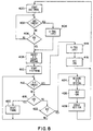
- FIG. 9 illustrates the steps of the Sinus Preference Algorithm of the present invention that may be implemented in the pacemaker of Figures 1 and 7 in conjunction with the overall function of the flowchart of Figure 8.
- the flowchart of Figures 9 and 10 employ certain of the acronyms defined above and others including RC for SPW Rate Change, RB for Recovery Beats, UTR or Upper Tracking Rate which is related to the Upper Rate Limit, SR for sensor-derived pacing rate over a full A-A pacing cycle, Non-R for non-refractory, SPVA or Sinus Preference V-A interval (i.e., the prolonged V-A interval), RD for the incremental Rate Drop that is allowed at a given pacing rate, and SRI for Sensor Rate Interval, which is the sensor-derived A-A interval.
- the SPW algorithm of Figures 9 and 10 is operational in the block 408 of Figure 8 in response to a VPE or VSE in block 404 or 406 and the preceding measured V-A interval from block 424.
- the SPW algorithm is invoked on time out of the SCI or the ASE as follows.
- the conditions are initialized in block 502 to reset the SCI, MRD, RC, RB, RD and SPW as shown in response to the setting of the SPW to zero in block 542 or other conditions of blocks 504 and 520.
- the SCI is programmable in seconds and commences to count down in seconds in this case.
- Each value for the parameters SCI, MRD, RD, RC, and RB is a separate physician programmable value within a possible range of values for each parameter and is indicated by "X" for simplicity.
- the SCI is monitored, and the relation of the UTR with SR and MRD is examined. If SCI is counted down to zero or timed out, and if UTR is less than the sensor-derived rate (SR) less the Maximum Rate Drop (MRD), then the starting conditions are reset in block 502. This insures that the algorithm is not followed if the UTR would be violated. If not, then the algorithm waits for the occurrence of a non-refractory ASE to occur during the SVA. As long as no Non-R ASE is detected, the state of the SCI counter/timer is continuously monitored. Either the time out of the SCI or a Non-R ASE can initiate the change to the SPVA under the Sinus Appropriate conditions illustrated in Figure 4 and set forth in block 508.
- SR sensor-derived rate
- MRD Maximum Rate Drop
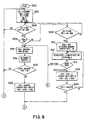
- the SPVA is set to the SVA
- the Current Rate is set to SR
- the MaxSPW is determined in accordance with the above formula in block 510.
- the Desired Rate is determined as the Current Rate less the Rate Drop (RD), and the delta is determined by the above formula.
- the MVA value (derived in block 424 of Figure 4) is compared to the SVA and the minimum is set to SPVA in block 516.
- the MaxSPW is determined from the above formula in block 518. If the sum of the SPVA, MaxSPW and PAV is less than SRI as found in block 520, then the Sinus Rate exceeds the sensor rate by more than the MRD, and the start values are reset to the programmed values "X" in block 502.
- the SPW is set to MaxSPW.
- the current pacing rate is determined to be equal to the rate corresponding inversely to the sum of the PAV and SPVA and SPW intervals, and the algorithm continues in Figure 10.
- next SPW is set to the current SPW plus delta , and the current rate is set to the rate corresponding inversely to the sum of the PAV and SPVA and SPW intervals.
- the next SPW is compared to MaxSPW in block 526, and, if equal to or greater, then the algorithm continues in Figure 10. If less, then the algorithm loops back to block 512. In this fashion, when the next SPW is equal to MaxSPW, from either block 522 or 526, the algorithm continues in Figure 10.
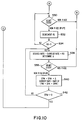
- the sense amplifiers are monitored in block 530. If a Non-R ASE is detected, then the SPVA for the next succeeding pacing cycle is again calculated in blocks 516 to 522. If a Non-R VSE is detected, then the RB number is decremented in block 532. When the RB count is decremented to zero as found in block 534, the Desired Rate of the next pacing cycle is set to the Current Rate plus RD in block 536, and delta is determined in block 536. The next sensed depolarization of the atrium in block 538 also causes the recalculation of the SPVA in blocks 516 - 522.
- the SPW is incremented again with delta, and the current rate is set to the inverse of the sum of PAV and SVA and SPW for the next pacing cycle in block 540. This continues as long as the SPW is greater than zero.
- the algorithm is reset at block 502 to the initial programmed operating conditions. Pacing at the sensor-derived pacing rate is re-commenced until the timeout of SCI or the sensing of a non-refractory ASE.
Claims (5)
- Frequenzadaptierender Doppelkammer-Schrittmacher-Impulsgenerator, der ausgebildet ist, um mit atriellen und ventrikulären Stimulations- und Meßelektroden (13, 15) verbunden zu werden, und atrielle und ventrikuläre Lese- bzw. Meßverstärker (17, 19) zum Erfassen bzw. Messen natürlicher atrieller und ventrikulärer Depolarisationen als erfasste atrielle bzw. ventrikuläre Ereignisse und atrielle und ventrikuläre Impulsgeneratoren (16, 18) zum Zuführen atrieller und ventrikulärer Stimulationsimpulse zum Atrium bzw. zum Ventrikel des Patienten bei einer einstellbaren Stimulationsrate bzw. -frequenz in Abhängigkeit von der natürlichen atriellen Depolarisationsrate des Patienten und von den physiologischen Herzleistungs-Anforderungen des Patienten, aufweist, wobei der Schrittmacher weiter aufweist:eine Einrichtung (21) zum Messen des Aktivitätsniveaus des Patienten und zum Bereitstellen eines Patienten-Aktivitätssensorsignals auf der Grundlage hiervon,eine Ventrikel-zu-Atrium-(V-A)-Escapeintervall-Zeitgebereinrichtung (330), die auf das Aktivitätssensorsignal des Patienten anspricht, um ein vom Sensor abgeleitetes V-A-Escapeintervall bereitzustellen, das sich auf die Aktivität des Patienten bezieht,eine Atriell-zu-Ventrikulär-(A-V)-Verzögerungseinrichtung (304) zum Einrichten eines A-V-Verzögerungsintervalls undzum zeitlichen Steuern der Abgabe eines ventrikulären Stimulationsimpulses durch den ventrikulären Impulsgenerator nach einem vorhergehenden erfassten atriellen Ereignis oder einem atriellen Stimulationsimpuls, wobei das Verstreichen eines V-A-Escapeintervalls, gefolgt vom Verstreichen eines A-V-Verzögerungsintervalls, einen Stimulationszyklus bildet und die atrielle und ventrikuläre Stimulationsrate in Bezug auf die Aktivität des Patienten festlegt,eine Einrichtung (330) zum Beenden des vom Sensor abgeleiteten V-A-Escapeintervalls nach Feststellung eines erfassten ventrikulären Ereignisses während der A-V-Verzögerung oder nach Abgabe eines ventrikulären Stimulationsimpulses am Ende der A-V-Verzögerung,eine Einrichtung (360) zur Feststellung des Auftretens einer atriellen Depolarisation während des vom Sensor abgeleiteten V-A-Escapeintervalls, um es als ein erfasstes atrielles Ereignis zu identifizieren,eine Einrichtung (330) zum Betreiben des atriellen Impulsgenerators, so daß er am Ende eines V-A-Escapeintervalls bei Nichtvorhandensein eines erfassten atriellen Ereignisses einen atriellen Stimulationsimpuls abgibt,eine Sinus-Präferenz-Fenstereinrichtung (302), die auf das Erfassen eines erfassten atriellen Ereignisses in einem V-A-Escapeintervall anspricht, um ein Sinus-Präferenz-Zeitfenster bereitzustellen,eine V-A-Escapeintervall-Verlängerungseinrichtung (330) zum Bereitstellen eines verlängerten V-A-Escapeintervalls von mindestens einem nachfolgenden Stimulationszyklus mit dem vom Sensor abgeleiteten V-A-Escapeintervall, verlängert um das Sinus-Präferenz-Zeitfenster, um eine synchronisierte ventrikuläre Stimulation ansprechend auf atrielle Sinusdepolarisationen, sofern sie vorhanden sind, im verlängerten V-A-Escapeintervall bereitzustellen, undeine Einrichtung (302) zum Einstellen der jeweiligen Dauer der Sinus-Präferenz-Zeitfenster ansprechend auf Nicht-Erfassungen einer atriellen Sinusdepolarisation innerhalb der verlängerten V-A-Escapeintervalle des nachfolgenden Stimulationszyklus, wobei der Schrittmacher gekennzeichnet ist durch:eine Dekrementiereinrichtung, welche aufweist:eine Zähleinrichtung (302) zum Bereitstellen eines Zählwerts aufeinanderfolgender Stimulationszyklen, die jeweils ein verlängertes V-A-Escapeintervall aufweisen, undeine Rücksetzeinrichtung, die bei Nichtvorhandensein eines erfassten atriellen Ereignisses in beliebigen der verlängerten V-A-Escapeintervalle für einen vorgegebenen Zählwert von Stimulationszyklen der Zähleinrichtung das Verkürzen des Sinus-Präferenz-Zeitfensters und dadurch das Verkürzen des verlängerten V-A-Escapeintervalls für den nächsten Stimulationszyklus bewirkt, wobeidie V-A-Escapeintervall-Verlängerungseinrichtung (330) bei Vorhandensein eines erfassten atriellen Ereignisses in einem Stimulationszyklus nach dem Verkürzen des verlängerten V-A-Escapeintervalls das Wiederherstellen des vollen Sinus-Präferenz-Zeitfensters im verlängerten V-A-Escapeintervall für die nächsten Stimulationszyklen bewirkt.
- Impulsgenerator nach Anspruch 1, bei dem:die Rücksetzeinrichtung bei fortgesetztem Nichtvorhandensein erfasster atrieller Ereignisse in den Stimulationszyklen nach dem ersten Zyklus mit einem verkürzten, verlängerten V-A-Escapeintervall betreibbar ist, um sukzessive das Sinus-Präferenz-Zeitfenster zu verkürzen, bis dieses auf Null verringert ist.
- Impulsgenerator nach Anspruch 1 oder 2, welcher weiter aufweist:eine Zeitgebereinrichtung zum zeitlichen Steuern sukzessiver Stimulationszyklen ohne erfasste atrielle Ereignisse, undeine Einrichtung, die auf eine vorgegebene Zeit der Zeitgebereinrichtung anspricht, um die V-A-Escapeintervall-Verlängerungseinrichtung so zu betreiben, daß sie das verlängerte V-A-Escapeintervall als ein Sinus-Prüfintervall bereitstellt, um eine atrielle Sinusrate nachzuweisen, die sich durch ein erfasstes atrielles Ereignis manifestiert, sofern vorhanden, innerhalb des Sinus-Präferenz-Zeitfensters.
- Impulsgenerator nach Anspruch 3, welcher weiter aufweist:wobei die Verlängerungseinrichtung zum Bereitstellen des verlängerten V-A-Escapeintervalls des nachfolgenden Stimulationszyklus als die Summe des gewählten größeren V-A-Escapeintervalls und des Sinus-Preferenz-Zeitfensters betreibbar ist.eine während des Sinus-Prüfintervalls betreibbare Einrichtung zur zeitlichen Erfassung des Auftretens eines erfassten atriellen Ereignisses bezüglich des vorhergehenden erfassten ventrikulären Ereignisses oder stimulierten ventrikulären, stimulierten Ereignisses und zum Bereitstellen eines gemessenen V-A-Escapeintervalls,eine Einrichtung zum Vergleichen des gemessenen V-A-Escapeintervalls mit dem vom Sensor abgeleiteten V-A-Escapeintervall und zum Auswählen des größeren von dem gemessenen V-A-Escapeintervall und dem vom Sensor abgeleiteten V-A-Escapeintervall als ein V-A-Escapeintervall für den nachfolgenden Stimulationszyklus,
- Impulsgenerator nach Anspruch 1 bis 4, ferner dadurch gekennzeichnet, daß wenn das V-A-Escapeintervall vollständig wiederhergestellt ist, das V-A-Escapeintervall über mehrere Herzzyklen derart wiederhergestellt verbleibt.
Applications Claiming Priority (3)
| Application Number | Priority Date | Filing Date | Title |
|---|---|---|---|
| US343166 | 1994-11-22 | ||
| US08/343,166 US5522859A (en) | 1993-09-29 | 1994-11-22 | Sinus preference method and apparatus for cardiac pacemakers |
| PCT/US1995/014898 WO1996015828A1 (en) | 1994-11-22 | 1995-11-13 | Sinus preference method and apparatus for cardiac pacemakers |
Publications (2)
| Publication Number | Publication Date |
|---|---|
| EP0796129A1 EP0796129A1 (de) | 1997-09-24 |
| EP0796129B1 true EP0796129B1 (de) | 2003-04-23 |
Family
ID=23344978
Family Applications (1)
| Application Number | Title | Priority Date | Filing Date |
|---|---|---|---|
| EP95939989A Expired - Lifetime EP0796129B1 (de) | 1994-11-22 | 1995-11-13 | Herzschrittmacher mit sinus-präferenz verfahren |
Country Status (7)
| Country | Link |
|---|---|
| US (2) | US5522859A (de) |
| EP (1) | EP0796129B1 (de) |
| JP (1) | JP2821028B2 (de) |
| AU (1) | AU4161696A (de) |
| CA (1) | CA2204363C (de) |
| DE (1) | DE69530513T2 (de) |
| WO (1) | WO1996015828A1 (de) |
Families Citing this family (57)
| Publication number | Priority date | Publication date | Assignee | Title |
|---|---|---|---|---|
| US5782886A (en) * | 1997-02-28 | 1998-07-21 | Vitatron Medical, B.V. | Pacemaker with improved hysteresis |
| DE19859651A1 (de) * | 1998-12-15 | 2000-06-21 | Biotronik Mess & Therapieg | Zweikammer-Herzschrittmacher |
| US6434424B1 (en) | 1998-12-28 | 2002-08-13 | Medtronic, Inc. | Regularization of ventricular rate during atrial tachyarrhythmia |
| US7203535B1 (en) | 1999-04-01 | 2007-04-10 | Cardiac Pacemakers, Inc. | System and method for classifying tachycardia arrhythmias having 1:1 atrial-to-ventricular rhythms |
| US6285907B1 (en) | 1999-05-21 | 2001-09-04 | Cardiac Pacemakers, Inc. | System providing ventricular pacing and biventricular coordination |
| US8064997B2 (en) | 1999-05-21 | 2011-11-22 | Cardiac Pacemakers, Inc. | Method and apparatus for treating irregular ventricular contractions such as during atrial arrhythmia |
| US6430438B1 (en) | 1999-05-21 | 2002-08-06 | Cardiac Pacemakers, Inc. | Cardiac rhythm management system with atrial shock timing optimization |
| US7142918B2 (en) * | 2000-12-26 | 2006-11-28 | Cardiac Pacemakers, Inc. | Apparatus and method for pacing mode switching during atrial tachyarrhythmias |
| US6351669B1 (en) | 1999-05-21 | 2002-02-26 | Cardiac Pacemakers, Inc. | Cardiac rhythm management system promoting atrial pacing |
| US7212860B2 (en) | 1999-05-21 | 2007-05-01 | Cardiac Pacemakers, Inc. | Apparatus and method for pacing mode switching during atrial tachyarrhythmias |
| US7181278B2 (en) | 1999-05-21 | 2007-02-20 | Cardiac Pacemakers, Inc. | Apparatus and method for ventricular rate regularization |
| US7062325B1 (en) | 1999-05-21 | 2006-06-13 | Cardiac Pacemakers Inc | Method and apparatus for treating irregular ventricular contractions such as during atrial arrhythmia |
| US6501988B2 (en) | 2000-12-26 | 2002-12-31 | Cardiac Pacemakers Inc. | Apparatus and method for ventricular rate regularization with biventricular sensing |
| US6442429B1 (en) | 1999-06-18 | 2002-08-27 | Medtronic, Inc. | Method and apparatus for diagnosis and treatment of arrhythmias |
| US6282447B1 (en) * | 1999-08-19 | 2001-08-28 | Intermedics Inc. | Cardiac stimulator with rate-adaptive PVARP |
| US6379300B1 (en) | 1999-10-08 | 2002-04-30 | Medtronic, Inc. | Telemtry system for implantable medical devices |
| US7239914B2 (en) | 2000-05-13 | 2007-07-03 | Cardiac Pacemakers, Inc. | Rate smoothing control |
| US6501987B1 (en) | 2000-05-26 | 2002-12-31 | Cardiac Pacemakers, Inc. | Rate smoothing control |
| US7039461B1 (en) | 2000-05-13 | 2006-05-02 | Cardiac Pacemakers, Inc. | Cardiac pacing system for prevention of ventricular fibrillation and ventricular tachycardia episode |
| US8512220B2 (en) | 2000-05-26 | 2013-08-20 | Cardiac Pacemakers, Inc. | Rate smoothing control |
| US6424865B1 (en) | 2000-07-13 | 2002-07-23 | Cardiac Pacemakers, Inc. | Ventricular conduction delay trending system and method |
| US6519495B1 (en) * | 2000-08-15 | 2003-02-11 | Cardiac Pacemakers, Inc. | Rate-adaptive therapy with sensor cross-checking |
| US6823214B1 (en) | 2000-09-08 | 2004-11-23 | Cardiac Pacemakers, Inc. | Self-calibrating rate-adaptive pacemaker |
| US6512951B1 (en) | 2000-09-14 | 2003-01-28 | Cardiac Pacemakers, Inc. | Delivery of atrial defibrillation shock based on estimated QT interval |
| US6829504B1 (en) | 2000-09-14 | 2004-12-07 | Cardiac Pacemakers, Inc. | System and method for preventing recurrence of atrial tachyarrhythmia |
| US7738955B2 (en) * | 2000-12-21 | 2010-06-15 | Medtronic, Inc. | System and method for ventricular pacing with AV interval modulation |
| US9931509B2 (en) | 2000-12-21 | 2018-04-03 | Medtronic, Inc. | Fully inhibited dual chamber pacing mode |
| US7245966B2 (en) | 2000-12-21 | 2007-07-17 | Medtronic, Inc. | Ventricular event filtering for an implantable medical device |
| US20020087198A1 (en) | 2000-12-29 | 2002-07-04 | Kramer Andrew P. | Apparatus and method for ventricular rate regularization |
| US6795734B2 (en) * | 2000-12-26 | 2004-09-21 | Cardiac Pacemakers, Inc. | Method and apparatus for display of ventricular electrograms |
| US6957100B2 (en) | 2000-12-26 | 2005-10-18 | Cardiac Pacemakers, Inc. | Method and system for display of cardiac event intervals in a resynchronization pacemaker |
| US6904316B2 (en) * | 2001-11-06 | 2005-06-07 | Cardiac Pacemakers, Inc. | Cardiac rhythm management system with maximum tracking rate (MTR) hysteresis |
| US7532929B2 (en) | 2004-02-23 | 2009-05-12 | Biotronik Crm Patent Ag | Adaptive ventricular rate smoothing during atrial fibrillation |
| US7248924B2 (en) * | 2004-10-25 | 2007-07-24 | Medtronic, Inc. | Self limited rate response |
| US7593773B2 (en) * | 2005-01-21 | 2009-09-22 | Medtronic, Inc. | Implantable medical device with ventricular pacing protocol including progressive conduction search |
| US7542799B2 (en) * | 2005-01-21 | 2009-06-02 | Medtronic, Inc. | Implantable medical device with ventricular pacing protocol |
| US7925344B2 (en) * | 2006-01-20 | 2011-04-12 | Medtronic, Inc. | System and method of using AV conduction timing |
| US8046063B2 (en) * | 2006-02-28 | 2011-10-25 | Medtronic, Inc. | Implantable medical device with adaptive operation |
| US7869872B2 (en) * | 2006-06-15 | 2011-01-11 | Medtronic, Inc. | System and method for determining intrinsic AV interval timing |
| US7894898B2 (en) * | 2006-06-15 | 2011-02-22 | Medtronic, Inc. | System and method for ventricular interval smoothing following a premature ventricular contraction |
| US7565196B2 (en) * | 2006-06-15 | 2009-07-21 | Medtronic, Inc. | System and method for promoting intrinsic conduction through atrial timing |
| US7783350B2 (en) * | 2006-06-15 | 2010-08-24 | Medtronic, Inc. | System and method for promoting intrinsic conduction through atrial timing modification and calculation of timing parameters |
| US7720537B2 (en) | 2006-07-31 | 2010-05-18 | Medtronic, Inc. | System and method for providing improved atrial pacing based on physiological need |
| US7715914B2 (en) * | 2006-07-31 | 2010-05-11 | Medtronic, Inc. | System and method for improving ventricular sensing |
| US7502647B2 (en) | 2006-07-31 | 2009-03-10 | Medtronic, Inc. | Rate smoothing pacing modality with increased ventricular sensing |
| US7515958B2 (en) | 2006-07-31 | 2009-04-07 | Medtronic, Inc. | System and method for altering pacing modality |
| US7502646B2 (en) * | 2006-07-31 | 2009-03-10 | Medtronic, Inc. | Pacing mode event classification with rate smoothing and increased ventricular sensing |
| US7856269B2 (en) | 2006-07-31 | 2010-12-21 | Medtronic, Inc. | System and method for determining phsyiologic events during pacing mode operation |
| US7689281B2 (en) | 2006-07-31 | 2010-03-30 | Medtronic, Inc. | Pacing mode event classification with increased ventricular sensing |
| US8086308B2 (en) * | 2007-06-27 | 2011-12-27 | Pacesetter, Inc. | Implantable medical device for identifying and managing intrinsic reentrant tachycardia |
| US7986993B1 (en) | 2007-06-27 | 2011-07-26 | Pacesetter, Inc. | Implantable cardiac device providing AV interval hysteresis to promote intrinsic conduction while providing PMT avoidance and method |
| US20090157133A1 (en) | 2007-12-13 | 2009-06-18 | Cardiac Pacemakers, Inc. | Supraventricular tachy sensing vector |
| EP2403593B1 (de) * | 2009-02-27 | 2014-04-09 | Medtronic, Inc | System für konditionales biventrikuläres pacing |
| US8396553B2 (en) | 2009-02-27 | 2013-03-12 | Medtronic, Inc. | System and method for conditional biventricular pacing |
| WO2010099421A1 (en) * | 2009-02-27 | 2010-09-02 | Medtronic, Inc. | A system and method for conditional biventricular pacing |
| US8478407B2 (en) | 2011-07-28 | 2013-07-02 | Medtronic, Inc. | Methods for promoting intrinsic activation in single chamber implantable cardiac pacing systems |
| US8543204B2 (en) | 2011-12-22 | 2013-09-24 | Medtronic, Inc. | Timing pacing pulses in single chamber implantable cardiac pacemaker systems |
Family Cites Families (22)
| Publication number | Priority date | Publication date | Assignee | Title |
|---|---|---|---|---|
| US3857399A (en) * | 1970-03-24 | 1974-12-31 | F Zacouto | Heart pacer |
| US3921642A (en) * | 1974-07-01 | 1975-11-25 | Thomas A Preston | Automatic rate adjustment pacer with natural rate searching means and method of operation |
| US4312355A (en) * | 1977-01-12 | 1982-01-26 | Medtronic B.V. | Heart pacemaker |
| US4257423A (en) * | 1978-11-06 | 1981-03-24 | Medtronic, Inc. | Medical device |
| US4556063A (en) * | 1980-10-07 | 1985-12-03 | Medtronic, Inc. | Telemetry system for a medical device |
| US4374382A (en) * | 1981-01-16 | 1983-02-15 | Medtronic, Inc. | Marker channel telemetry system for a medical device |
| US4428378A (en) * | 1981-11-19 | 1984-01-31 | Medtronic, Inc. | Rate adaptive pacer |
| US4856523A (en) * | 1987-10-08 | 1989-08-15 | Siemens-Pacesetter, Inc. | Rate-responsive pacemaker with automatic mode switching and/or variable hysteresis rate |
| US4951667A (en) * | 1987-11-25 | 1990-08-28 | Medtronic, Inc. | Dual chamber activity responsive pacer |
| EP0381799B2 (de) * | 1989-02-10 | 2003-04-23 | St. Jude Medical AB | Implantierbarer Herzschrittmacher mit auf einen Maximalwert begrenzter Folgefrequenz der Stimulationen von Herzmuskelkontraktionen |
| US5127404A (en) * | 1990-01-22 | 1992-07-07 | Medtronic, Inc. | Telemetry format for implanted medical device |
| US5085215A (en) * | 1990-03-20 | 1992-02-04 | Telectronics Pacing Systems, Inc. | Metabolic demand driven rate-responsive pacemaker |
| US5154170A (en) * | 1990-08-14 | 1992-10-13 | Medtronic, Inc. | Optimization for rate responsive cardiac pacemaker |
| US5144949A (en) * | 1991-03-15 | 1992-09-08 | Medtronic, Inc. | Dual chamber rate responsive pacemaker with automatic mode switching |
| FR2682878B1 (fr) * | 1991-10-25 | 1993-12-10 | Ela Medical | Procede de reglage automatique de l'hysteresis dans un stimulateur cardiaque. |
| US5247930A (en) * | 1992-02-04 | 1993-09-28 | Vitatron Medical, B.V. | Dual chamber pacing system with dynamic physiological tracking and method of timing delivered stimulus for optimized synchronous pacing |
| US5284491A (en) * | 1992-02-27 | 1994-02-08 | Medtronic, Inc. | Cardiac pacemaker with hysteresis behavior |
| US5237992A (en) * | 1992-03-05 | 1993-08-24 | Siemens Pacesetter, Inc. | Implantable pacemaker providing hysteresis in dual-chamber modes |
| US5282838A (en) * | 1992-06-08 | 1994-02-01 | Cardiac Pacemakers, Inc. | Dual chamber cardiac pacemaker employing hysteresis to maximize the number of normally conducted ventricular beats with an optimum A-V delay for paced ventricular beats |
| US5312452A (en) * | 1992-11-03 | 1994-05-17 | Cardiac Pacemakers, Inc. | Cardiac rhythm management device with automatic optimization of performance related pacing parameters |
| US5374281A (en) * | 1993-02-09 | 1994-12-20 | Siemens Pacesetter, Inc. | Hysteresis in a rate-responsive pacemaker |
| WO1995009661A2 (en) * | 1993-09-29 | 1995-04-13 | Medtronic, Inc. | Sinus preference method and apparatus for cardiac pacemakers |
-
1994
- 1994-11-22 US US08/343,166 patent/US5522859A/en not_active Expired - Lifetime
-
1995
- 1995-11-13 WO PCT/US1995/014898 patent/WO1996015828A1/en active IP Right Grant
- 1995-11-13 AU AU41616/96A patent/AU4161696A/en not_active Abandoned
- 1995-11-13 DE DE69530513T patent/DE69530513T2/de not_active Expired - Lifetime
- 1995-11-13 JP JP8516968A patent/JP2821028B2/ja not_active Expired - Lifetime
- 1995-11-13 CA CA002204363A patent/CA2204363C/en not_active Expired - Fee Related
- 1995-11-13 EP EP95939989A patent/EP0796129B1/de not_active Expired - Lifetime
-
1996
- 1996-03-05 US US08/611,357 patent/US5674257A/en not_active Expired - Lifetime
Also Published As
| Publication number | Publication date |
|---|---|
| DE69530513T2 (de) | 2003-11-13 |
| AU4161696A (en) | 1996-06-17 |
| CA2204363C (en) | 2003-12-23 |
| CA2204363A1 (en) | 1996-05-30 |
| JP2821028B2 (ja) | 1998-11-05 |
| US5674257A (en) | 1997-10-07 |
| JPH09512738A (ja) | 1997-12-22 |
| WO1996015828A1 (en) | 1996-05-30 |
| EP0796129A1 (de) | 1997-09-24 |
| US5522859A (en) | 1996-06-04 |
| DE69530513D1 (de) | 2003-05-28 |
Similar Documents
| Publication | Publication Date | Title |
|---|---|---|
| EP0796129B1 (de) | Herzschrittmacher mit sinus-präferenz verfahren | |
| US7783355B2 (en) | Dynamic adjustment of capture management “safety margin” | |
| US5741308A (en) | Dual-chamber implantable pacemaker and method of operating same for automatically setting the pacemaker's AV interval as a function of a natural measured conduction time | |
| EP0559847B1 (de) | Taktempfindlicher zweikammer-herzschrittmacher mit automatischer umschaltung der betriebsart | |
| AU694258B2 (en) | Atrial and ventricular capture detection and threshold-seeking pacemaker | |
| AU648966B2 (en) | Implantable pacemaker including means and method of terminating a pacemaker-mediated tachycardia during rate adaptive pacing | |
| US5873895A (en) | Pacemaker and method of operating same that provides functional atrial cardiac pacing with ventricular support | |
| US5441523A (en) | Forced atrioventricular synchrony dual chamber pacemaker | |
| EP0751804B1 (de) | Vorrichtung eines zweikammerherzschrittmachers | |
| US5237992A (en) | Implantable pacemaker providing hysteresis in dual-chamber modes | |
| EP0431437B1 (de) | System und Verfahren zur Erhaltung der Reizimpulsamplitude bei Batterienentladung mittels selbstregulierender Stromaufnahme | |
| AU658639B2 (en) | System and method for preventing atrial competition during sensor-driven operation of a dual-chamber pacemaker | |
| WO1992016258A9 (en) | Dual chamber rate responsive pacemaker with automatic mode switching | |
| WO2005009529A2 (en) | Atrial capture management during atrial and ventricular pacing | |
| JPH06197993A (ja) | デュアルチャンバペースメーカおよびその作動方法 | |
| US5374281A (en) | Hysteresis in a rate-responsive pacemaker | |
| EP0709114B1 (de) | Zweikammer-Herzschrittmacher-System mit verbesserter Umschaltung zwischen dem synchronen und dem asynchronen Modus | |
| JPH06205846A (ja) | デュアルチャンバペースメーカおよびその作動方法 | |
| US5127402A (en) | System and method for maintaining stimulation pulse amplitude at battery depletion by self-regulating current drain usage | |
| EP0757577B1 (de) | Herzschrittmacher mit detektion eines vasoneurotischen kollapses | |
| US5228439A (en) | System and method for maintaining proper device operation at battery depletion by self-regulating current drain usage | |
| US20020147469A1 (en) | Device and method for ventricular tracking and pacing | |
| WO1995009661A2 (en) | Sinus preference method and apparatus for cardiac pacemakers |
Legal Events
| Date | Code | Title | Description |
|---|---|---|---|
| PUAI | Public reference made under article 153(3) epc to a published international application that has entered the european phase |
Free format text: ORIGINAL CODE: 0009012 |
|
| 17P | Request for examination filed |
Effective date: 19970623 |
|
| AK | Designated contracting states |
Kind code of ref document: A1 Designated state(s): CH DE FR LI NL SE |
|
| 17Q | First examination report despatched |
Effective date: 20020131 |
|
| GRAG | Despatch of communication of intention to grant |
Free format text: ORIGINAL CODE: EPIDOS AGRA |
|
| RTI1 | Title (correction) |
Free format text: CARDIAC PACEMAKERS USING SINUS PREFERENCE METHOD |
|
| RTI1 | Title (correction) |
Free format text: CARDIAC PACEMAKERS USING SINUS PREFERENCE METHOD |
|
| GRAG | Despatch of communication of intention to grant |
Free format text: ORIGINAL CODE: EPIDOS AGRA |
|
| GRAH | Despatch of communication of intention to grant a patent |
Free format text: ORIGINAL CODE: EPIDOS IGRA |
|
| GRAH | Despatch of communication of intention to grant a patent |
Free format text: ORIGINAL CODE: EPIDOS IGRA |
|
| GRAA | (expected) grant |
Free format text: ORIGINAL CODE: 0009210 |
|
| AK | Designated contracting states |
Designated state(s): CH DE FR LI NL SE |
|
| REG | Reference to a national code |
Ref country code: CH Ref legal event code: EP |
|
| REG | Reference to a national code |
Ref country code: CH Ref legal event code: NV Representative=s name: A. BRAUN, BRAUN, HERITIER, ESCHMANN AG PATENTANWAE |
|
| REF | Corresponds to: |
Ref document number: 69530513 Country of ref document: DE Date of ref document: 20030528 Kind code of ref document: P |
|
| REG | Reference to a national code |
Ref country code: SE Ref legal event code: TRGR |
|
| PGFP | Annual fee paid to national office [announced via postgrant information from national office to epo] |
Ref country code: SE Payment date: 20031106 Year of fee payment: 9 |
|
| PGFP | Annual fee paid to national office [announced via postgrant information from national office to epo] |
Ref country code: CH Payment date: 20031219 Year of fee payment: 9 |
|
| ET | Fr: translation filed | ||
| PLBE | No opposition filed within time limit |
Free format text: ORIGINAL CODE: 0009261 |
|
| STAA | Information on the status of an ep patent application or granted ep patent |
Free format text: STATUS: NO OPPOSITION FILED WITHIN TIME LIMIT |
|
| 26N | No opposition filed |
Effective date: 20040126 |
|
| PG25 | Lapsed in a contracting state [announced via postgrant information from national office to epo] |
Ref country code: SE Free format text: LAPSE BECAUSE OF NON-PAYMENT OF DUE FEES Effective date: 20041114 |
|
| PG25 | Lapsed in a contracting state [announced via postgrant information from national office to epo] |
Ref country code: LI Free format text: LAPSE BECAUSE OF NON-PAYMENT OF DUE FEES Effective date: 20041130 Ref country code: CH Free format text: LAPSE BECAUSE OF NON-PAYMENT OF DUE FEES Effective date: 20041130 |
|
| EUG | Se: european patent has lapsed | ||
| REG | Reference to a national code |
Ref country code: CH Ref legal event code: PL |
|
| PGFP | Annual fee paid to national office [announced via postgrant information from national office to epo] |
Ref country code: NL Payment date: 20061006 Year of fee payment: 12 |
|
| NLV4 | Nl: lapsed or anulled due to non-payment of the annual fee |
Effective date: 20080601 |
|
| PG25 | Lapsed in a contracting state [announced via postgrant information from national office to epo] |
Ref country code: NL Free format text: LAPSE BECAUSE OF NON-PAYMENT OF DUE FEES Effective date: 20080601 |
|
| PGFP | Annual fee paid to national office [announced via postgrant information from national office to epo] |
Ref country code: DE Payment date: 20101130 Year of fee payment: 16 |
|
| PGFP | Annual fee paid to national office [announced via postgrant information from national office to epo] |
Ref country code: FR Payment date: 20111128 Year of fee payment: 17 |
|
| REG | Reference to a national code |
Ref country code: FR Ref legal event code: ST Effective date: 20130731 |
|
| REG | Reference to a national code |
Ref country code: DE Ref legal event code: R119 Ref document number: 69530513 Country of ref document: DE Effective date: 20130601 |
|
| PG25 | Lapsed in a contracting state [announced via postgrant information from national office to epo] |
Ref country code: DE Free format text: LAPSE BECAUSE OF NON-PAYMENT OF DUE FEES Effective date: 20130601 |
|
| PG25 | Lapsed in a contracting state [announced via postgrant information from national office to epo] |
Ref country code: FR Free format text: LAPSE BECAUSE OF NON-PAYMENT OF DUE FEES Effective date: 20121130 |