EP0431437B1 - System und Verfahren zur Erhaltung der Reizimpulsamplitude bei Batterienentladung mittels selbstregulierender Stromaufnahme - Google Patents
System und Verfahren zur Erhaltung der Reizimpulsamplitude bei Batterienentladung mittels selbstregulierender Stromaufnahme Download PDFInfo
- Publication number
- EP0431437B1 EP0431437B1 EP90122538A EP90122538A EP0431437B1 EP 0431437 B1 EP0431437 B1 EP 0431437B1 EP 90122538 A EP90122538 A EP 90122538A EP 90122538 A EP90122538 A EP 90122538A EP 0431437 B1 EP0431437 B1 EP 0431437B1
- Authority
- EP
- European Patent Office
- Prior art keywords
- rate
- battery
- battery voltage
- current drain
- pacemaker
- Prior art date
- Legal status (The legal status is an assumption and is not a legal conclusion. Google has not performed a legal analysis and makes no representation as to the accuracy of the status listed.)
- Revoked
Links
Images

Classifications
-
- A—HUMAN NECESSITIES
- A61—MEDICAL OR VETERINARY SCIENCE; HYGIENE
- A61N—ELECTROTHERAPY; MAGNETOTHERAPY; RADIATION THERAPY; ULTRASOUND THERAPY
- A61N1/00—Electrotherapy; Circuits therefor
- A61N1/18—Applying electric currents by contact electrodes
- A61N1/32—Applying electric currents by contact electrodes alternating or intermittent currents
- A61N1/36—Applying electric currents by contact electrodes alternating or intermittent currents for stimulation
- A61N1/372—Arrangements in connection with the implantation of stimulators
- A61N1/378—Electrical supply
-
- A—HUMAN NECESSITIES
- A61—MEDICAL OR VETERINARY SCIENCE; HYGIENE
- A61N—ELECTROTHERAPY; MAGNETOTHERAPY; RADIATION THERAPY; ULTRASOUND THERAPY
- A61N1/00—Electrotherapy; Circuits therefor
- A61N1/18—Applying electric currents by contact electrodes
- A61N1/32—Applying electric currents by contact electrodes alternating or intermittent currents
- A61N1/36—Applying electric currents by contact electrodes alternating or intermittent currents for stimulation
- A61N1/362—Heart stimulators
- A61N1/365—Heart stimulators controlled by a physiological parameter, e.g. heart potential
- A61N1/36514—Heart stimulators controlled by a physiological parameter, e.g. heart potential controlled by a physiological quantity other than heart potential, e.g. blood pressure
-
- A—HUMAN NECESSITIES
- A61—MEDICAL OR VETERINARY SCIENCE; HYGIENE
- A61N—ELECTROTHERAPY; MAGNETOTHERAPY; RADIATION THERAPY; ULTRASOUND THERAPY
- A61N1/00—Electrotherapy; Circuits therefor
- A61N1/18—Applying electric currents by contact electrodes
- A61N1/32—Applying electric currents by contact electrodes alternating or intermittent currents
- A61N1/36—Applying electric currents by contact electrodes alternating or intermittent currents for stimulation
- A61N1/362—Heart stimulators
- A61N1/37—Monitoring; Protecting
- A61N1/3706—Pacemaker parameters
- A61N1/3708—Pacemaker parameters for power depletion
Definitions
- the present invention relates generally to implantable cardiac pacemakers, and more specifically to rate responsive pacemakers wherein the upper rate is limited as the battery approaches its end-of-life (EOL).
- EOL end-of-life
- the invention can be used with any high power consumption features within an implantable device to extend the longevity of the battery by limiting the extent to which these features may be utilized.
- Implantable cardiac pacemakers are powered by a battery within the pacemaker housing. Once implanted, it is difficult to determine the battery's state of depletion and, thus, the need for replacement. Although the surgery required for replacement is relatively minor, the associated risks of complications to the patient are ever present. In general, it is considered better to avoid replacement of a properly functioning pacemaker until absolutely necessary.
- EOL is defined as the point in time in which the pacemaker pulse amplitude is reduced to approximately 50 percent of the programmed value.
- physicians estimate the remaining battery capacity by subtracting the "nominal" current drain of the pacemaker, usually specified at 5 volts with 100% pacing at a rate of 70 pulses-per-minute (ppm), from the theoretical available amp-hour capacity of the battery.
- Patent No. 4,556,061 to Barreras et al. the physician must still accurately predict the power consumption for the remaining period.
- physicians have to schedule more frequent follow-up visits to accurately monitor the replacement time and still avoid premature surgical replacement.
- pacer output amplitude, pulse width, and rate Current drain on a battery is largely dictated by the pacer output amplitude, pulse width, and rate. Programmability of these pacemaker parameters offers some flexibility to safely prolong the longevity of the battery. For example, it is well known that the battery life can be increased anywhere from 3 to 9 months by programming the rate to 70 instead of 90 beats-per-minute (bpm). However, not all patients can tolerate being paced at 70 bpm. Active patients need a higher rate during exercise. In patients with a normal sinus node, higher rates may be achieved with a dual chamber pacemaker, wherein the atrial rate is sensed and the ventricles are stimulated a short delay later (mimicking a normal heart). During exercise, the atrial rate may vary between 70 and 120 bpm or more.
- rate responsive pacemakers can increase the pacing rate according to an additional sensor (accelerometer or "activity” sensor, oxygen saturation, QT measurements, respiration rate, temperature, etc.).
- the purpose of such pacemakers is to accelerate the rate when the atrium is incompetent, that is, non-responsive to exercise stress or prone to atrial flutter or fibrillation.
- the amount of current drain on the battery can change quite rapidly as the pacing rate of the pacer may change from a low rate to a high rate. This is especially true where the patient's own intrinsic rhythm is able to sustain the patient's needs at low activity levels (a low current drain condition), but where stimulated pacing is required in one or both chambers of the heart at a high activity level (a high current drain condition).
- a low current drain condition a low current drain condition
- stimulated pacing is required in one or both chambers of the heart at a high activity level
- a high current drain condition Unfortunately, such large variations in current drain can cause a sudden battery voltage drop below the EOL voltage level such that the possibility exists that the battery voltage could drop low enough to cause loss of capture.
- the increase in current drain could dramatically reduce or even eliminate the safety margin associated with the last reported recommended replacement time (RRT) of the pacer, particularly when the last reported RRT is based on the current drain while the patient was at the rest rate.
- RRT recommended replacement time
- GB 2026870, US-A-4 416 282, US-A-4 390 020 and EP-A-0 344 878 disclose the features found in the precharacterising portion of claim 1 of the present application.
- GB 2026870 relates to an arrangement in which, once the voltage drops below a predetermined threshold, the pulse amplitude is reduced and the pulse width broadened to maintain the overall pulse energy.
- US-A-4 416 282 relates to an arrangement including a main battery and an emergency battery. When the emergency mode takes control a fixed rate signal with defined wave shape is applied.
- US-A-4 390 020 discloses an arrangement in which the pulse widths are dependent on the prevailing source voltage.
- EP-A-0 344 878 output pacing capacitors are provided and the charge level thereof is selected as a function of the end of service battery voltage.
- pacemaker functionality has been extended to automatic adjustment of pacemaker parameters, storing and telemetering of intracardiac electrograms (EGMs), processing multiple sensors, detecting and breaking arrhythmias and recognizing waveform patterns.
- EGMs intracardiac electrograms
- the current drain of the pacemaker may also be significantly influenced by the duty cycle of the microprocessor in performing these functions. Without careful monitoring of the battery voltage, these high current drain situations may cause a temporary drop in available battery voltage, increase the risk of loss of capture, and dramatically use up the remaining battery capacity.
- pacemaker which can regulate its own current drain usage, conserve the limited battery energy towards EOL, prevent loss of capture by limiting high current drain modes, and ultimately eliminate premature replacement of the pacemaker by eliminating the unpredictable nature of the RRT to EOL interval. Furthermore, this pacemaker should not burden the physician by increasing the number of follow-up visits near EOL.
- the present invention may be used to limit power consumption as the battery approaches and exceeds the RRT.
- the present invention is capable of selectively altering operating parameters, based on a predetermined priority, to provide the longest possible active life for the pacemaker, while still providing a good quality of life as required by the patient's physiological needs. These actions help conserve the limited remaining battery energy and prevent loss, of capture.
- an implantable pacemaker comprising:
- a method of maintaining a constant stimulation pulse amplitude as the battery approaches depletion and preventing rapid depletion of a battery in an implantable stimulation device comprising the steps of:
- the present invention includes an implantable cardiac device having conventional components including a battery, a pulse generator for generating stimulating pulses, sense amplifiers for sensing cardiac signals, and a timing and control means.
- the device also includes a battery threshold detector for detecting a predetermined threshold level of the battery, having a high current drain mode of operation and at least two successively lower current drain modes of operation, and a processing means for switching to a successively lower current drain mode each time the battery threshold detector indicates that the battery voltage is below a prescribed threshold. This configuration allows a significant reduction in current drain.
- the implantable cardiac device is a rate responsive pacemaker.
- the pacemaker will automatically regulate its current drain usage by limiting the pacing rate to a value less than the sensor-indicated rate. This is achieved by continuously monitoring the battery voltage for the occurrence of a voltage at or below the predetermined threshold during rate responsive pacing. If such a voltage is detected, the allowable maximum sensor rate is automatically reduced (which, in turn, reduces the battery current drain). This new allowable maximum sensor rate remains in effect until the battery voltage is above the predetermined threshold or until the allowable maximum sensor rate is otherwise reset. As the battery continues to deplete, the allowable maximum sensor rate will eventually reduce the pacing rate to the programmed rest rate, or "base" rate, effectively disabling rate responsive pacing. In an alternative embodiment, the rate could even go lower than the rest rate.
- the pacemaker is switching from a high current drain mode (rate responsive pacing at a high rate), to a lower current drain mode (rate responsive pacing at successively lower rates) until the battery voltage is above the predetermined threshold.
- the invention controls the extent to which other high current drain modes can be utilized by the pacemaker once the predetermined threshold has been reached.
- the invention described herein further contemplates a method for maintaining output amplitude at battery depletion by self-regulating current drain usage. In one embodiment, this is achieved by reducing the rate of a rate responsive pacemaker when the battery voltage reaches a predetermined threshold value. In a second embodiment, the pacemaker is switched from a high current drain mode to a successively lower current drain mode until the battery voltage is above the predetermined threshold.
- the present invention does not require an increase in physician follow-up as the battery approaches RRT. Rather, its self-regulation of high current drain features allows the same follow-up schedule as VVI pacemakers with an increase in reliability and confidence.
- Fig. 1 shows the estimated discharge characteristics of a lithium iodide battery cell as is commonly used in many pacemakers today. These cells may be characterized as a fixed voltage source, with a stable open circuit voltage and an internal impedance which increases over time. Therefore, the available terminal voltage will vary inversely with the current drain from the battery, due to the internal voltage drop across the internal cell impedance.
- the current drain is significantly influenced by the rate at which the pacemaker is delivering stimulating pulses.
- Point “A" in Fig. 1 represents a patient with a rate responsive pacemaker wherein the patient is resting, therefore the current drain is low, say, at 20 uA. If the patient should suddenly need a high increase in rate, the current drain may increase to, say, 33 uA, and the available battery voltage would drop to 2.0 volts as indicated at point "B". It can therefore be seen that this increase in rate can cause a sudden battery voltage drop below the EOL voltage level such that the possibility exists that the battery voltage could drop low enough to cause loss of capture.
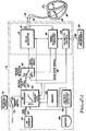
- FIG. 2A A block diagram of the present invention, coupled to a rate responsive pacer, is shown in Fig. 2A.
- a complete description of the rate responsive pacemaker is included in U.S. Patent No. 4,940,053, entitled “Energy Controlled Rate-Responsive Pacemaker Having Automatically Adjustable Control Parameters," and U.S. Patent No. 4,940,052, entitled “Microprocessor Controlled Rate-Responsive Pacemaker Having Automatic Rate Response Threshold Adjustment.” These patents are assigned to the same assignee as is the present application.
- the rate responsive pacemaker functions as follows.
- the pacemaker 10 includes a conventional pacemaker chip 12 which has a pulse generator 14 for generating stimulating pulses 16 to the heart 30.
- Sense amplifiers (not shown) are employed to sense cardiac events and to communicate this information to timing and control circuitry 18.
- the timing and control circuitry 18 controls a base rate signal 20 for the pulse generator 14 and controls the inhibition of a stimulus in the event of a sensed cardiac signal.
- Telemetry circuits 22 are connected electrically to the timing and control circuitry 18.
- An external programmer 24 is used to noninvasively send programming signals to the telemetry circuits 22. These programming signals are depicted symbolically as the wavy line 26 in Fig. 2A. It is noted that such signals may be sent bi-directionally between the external programmer 24 and the pacemaker 10. In this way the external programmer 24 can noninvasively alter the pacemaker's programmable parameters.
- the pulse generator 14 is connected electrically to the patient's heart 30 via a lead 32.
- the pulse generator 14 may be connected to the atrium 34 and the ventricle 36 via two leads 32 and 38, respectively.
- These leads 32 and 38 may be either unipolar leads, bipolar leads, or other multi-pole leads, all of which are known in the art.
- the pacemaker 10 further includes a rate responsive sensor 40 for sensing the physiological needs of the patient.
- the rate responsive sensor 40 is a piezoelectric sensor which detects physical activity.
- the present invention is not restricted to this type of sensor and could be used with any of the known rate responsive sensors (QT, temperature, oxygen saturation, impedance, pre-ejection period (PEP), minute volume, accelerometers, etc.). Since the invention described herein is independent of the type of sensor, hereinafter the sensor which is used to change the pacing rate shall simply be referred to as the "RR sensor".
- the RR sensor 40 is shown in Fig. 2A as being included within the pacemaker 10, it is to be understood that the RR sensor 40 could also be included within, or coupled to, the leads 32 and 38, or otherwise placed external to the pacemaker 10.
- the output of the RR sensor 40 is measured during each pacing cycle by the RR processor 42.
- the RR processor 42 includes means for converting the raw signal 44 to a sensor-indicated rate signal 62.
- the sensor-indicated rate signal 62 is based on the energy content of the raw signal 44.
- the conversion may be accomplished in several ways, using conventional techniques: typically by a transfer curve, look-up table (stored or programmed into the memory 68), algorithmically, or in hardware, software or a combination thereof.
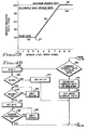
- the preferred transfer curve is shown in Fig. 2B, wherein the physician may program a Maximum Sensor Rate (MSR) 50, a Base Rate 52 (or minimum rate), and the slope 54 and threshold 57 therebetween. Based on the energy content (x-axis), a sensor-indicated rate may be determined.
- MSR Maximum Sensor Rate
- Base Rate 52 or minimum rate
- the rate responsive pacer may operate in either a SENSOR ON mode or a SENSOR OFF mode which can be selected by an appropriate programming signal received from the external programmer 24.
- a switch 60 is employed to select either the base rate signal 20 (during SENSOR OFF mode) determined by the timing and control circuitry 18 or the sensor-indicated rate signal 62 (during SENSOR ON mode) determined by the RR processor 42.
- a battery threshold detector 64 connected to a battery 66, is used to detect a voltage above or below a predetermined threshold.
- the predetermined threshold is the result of an impedance level detected at RRT, however, other threshold levels may be contemplated without deviating from the basic teaching of the invention. If the pacemaker 10 is pacing at an elevated rate due to exercise or stress and the battery 66 is at or below the RRT threshold level, then the battery threshold detector 64 triggers the RR processor 42 to decrease the current pacing rate by a small amount. This decreasing of the pacemaker rate will continue until the battery 66 is above the RRT threshold, or until the current rate reaches the Base Rate.
- the decreasing of the pacemaker rate will continue until the battery 66 is above the RRT threshold, or until the current rate reaches a rate lower than the Base Rate. This reduction of pacing rate at RRT ensures that the remaining replacement time before EOL will not be rapidly used up, capture will be maintained, and that rate responsive modes can be utilized for as long as possible.
- a method for maintaining output amplitude at battery depletion is shown.
- a ventricular pacing cycle is initiated at 100.
- the battery is measured at 102.
- the battery voltage is compared to a predetermined threshold at step 104. If the battery voltage is above the predetermined threshold, then the RR sensor is measured and the sensor-indicated rate is determined at 120.
- the sensor-indicated rate is compared to the current rate: if they are equal, no change in rate is initiated at 124 and the rate response loop ends at 125. If the sensor-indicated rate is greater than the current rate, then the current rate is compared to the (programmed) Maximum Sensor Rate at 126. If they are equal, no change in rate is initiated and the rate response loop ends at 125. If the current rate is below the (programmed) Maximum Sensor Rate, then the pacing rate is incremented by "n" steps at 128. In the preferred embodiment, "n" equal 1 step.
- the current rate is compared to the Base Rate at 130. If the current rate is equal to the Base Rate, the rate response loop ends at 125. If the current rate is above the Base Rate, then the pacing rate is decremented by "n" steps at 132. Finally, control will loop back to repeat the pacing cycle at 100, providing that rate responsive pacing has not been turned off at 136.
- an "allowable" maximum sensor rate is used to provide an intermediate rate limit based on battery measurements detected below threshold.
- the Allowable Maximum Sensor Rate (AMSR) 56 is adjustable between the Base Rate 52 and the (programmed) Maximum Sensor Rate (MSR) 50.
- the RR processor 42 decreases the current rate by at least one 1 step and sets the AMSR to the new current rate.
- the AMSR can be stored in a counter within RR processor 42 or external to it or at a location within memory 68. The AMSR will continue to be decremented until the RR processor 42 detects at least two consecutive battery measurements above threshold or until the current rate reaches the Base Rate. When the former instance occurs, the AMSR is permitted to increment back towards the programmed Maximum Sensor Rate.
- the rate responsive mode will be suspended until a magnet 70 is applied to reset a reed switch 72 in the pacemaker 10 (Fig. 2A). This additional feature enables greater rate responsiveness for the patient by preventing a single occurrence of the current rate being equal to the Base Rate from disabling the rate response mode.
- the pacemaker 10 will not automatically return to rate responsive pacing immediately upon reset of the reed switch 70. Instead, the pacemaker waits for a programming command from the physician via the external programmer 24. This feature allows the physician sufficient time to determine the status of the battery before re-enabling the rate responsive mode.
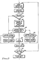
- Fig. 4A and 4B describe this preferred embodiment, wherein Fig. 4A shows the steps taken when the battery is above threshold and Fig. 4B shows the steps taken when the battery is below threshold, and wherein like elements are numbered similarly as in Fig. 3.
- Fig. 4A once RR programming has been turned ON, counters A and B are initialized to zero and the Allowable Maximum Sensor Rate (AMSR) is set equal to the programmed Maximum Sensor Rate (MSR) at step 98.
- a ventricular pacing cycle is initiated at 100. Following the stimulus, the battery is measured at 102. The battery voltage is compared to a predetermined threshold at step 104. If the battery voltage is above the predetermined threshold, then counter A is checked for "n" consecutive events, i.e., when the counter is zero at step 106. If the counter A is not at zero (which only occurs after at least one measurement below the predetermined threshold and is described in conjunction with Fig. 4B), then counter A is decremented at 108. If "n" consecutive events have occurred, then counter B is reset to zero at 110. (This will become meaningful later--after the complete operation of the system is described.)
- the AMSR is compared to the programmed MSR. If they are equal, as is the case at BOL, the RR sensor is measured at 120 and rate responsive pacing continues as described in Fig. 3. If they are not equal (which only occurs after at least one measurement below the predetermined threshold and is described in conjunction with Fig. 4B), the AMSR will gradually be incremented towards the MSR at step 114, that is, if the battery voltage is above the predetermined threshold for "n" consecutive cycles, the Allowable Maximum Sensor Rate is adjusted toward the (programmed) Maximum Sensor Rate.
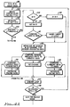
- Fig. 4B the steps are shown for a battery measurement which is below threshold.
- the current rate is compared to the Base Rate at 140. If the current rate is greater than the Base Rate, then the current rate is decremented by at least one step at 142 and the AMSR is set equal to the new current rate at 144.
- counter B is incremented at 146. If, at 148, counter B is less than 255 (or some other desired number of counts), then counter A is set to "n" at 150, thus beginning the search for "n" consecutive battery measurements above threshold. In the preferred embodiment, "n” is set to two. If counter B is equal to 255 counts, then the pacemaker waits for a magnet to be applied at steps 152 and 154, effectively suspending rate responsive pacing. Once the magnet is applied, counter B is reset to zero at 156 and the pacemaker waits for a reprogramming signal from the external programmer at step 158 and 159.
- High current drain modes include rate responsive pacing, automatic capture verification, automatic amplitude adjustment, automatic sensitivity adjustment, telemetry transmission of ECG data or measurements, waveform analysis, tachycardia or arrhythmia recognition, or any other features which increase microprocessor processing time.
- the pacemaker of the present invention would include a means for switching from a high current drain mode to a successively lower current drain mode whenever the battery threshold detector indicates that the battery voltage is below a prescribed threshold.
- Low current drain modes would be achieved by altering or limiting parameters such as reducing the sampling rate, pacing rate, or otherwise reducing the duty cycle of the microprocessor.
- the present invention may incorporate a plurality of thresholds such that these high current drain features may be switched to lower current drain modes according to a predetermined priority based on basic life support and quality of life.
- the advantages of the present invention result in extending the longevity of the pacemaker while providing a higher quality of life for the patient for as long as possible, making the method of the present invention a highly desirable enhancement to implantable cardiac pacemaker therapy.
Claims (13)
- Implantierbarer Schrittmacher, umfassend:eine Batterie (66), die eine Batteriespannung hat, welche abhängig von der Stromentnahme aus der Batterie ist;ein Batteriespannungsschwellenwertdetektor (64) zum Überwachen der Batteriespannung der Batterie, wobei der Batteriespannungsschwellenwertdetektor (64) anzeigt, wann die Batteriespannung zumindest auf eine erste vorbestimmte Spannung abfällt;ein Impulsgenerator (14) zum Erzeugen von Reizimpulsen an einem Patientenherz; wobei die Reizimpulse eine konstante Amplitude haben, wenn die Batteriespannung über der ersten vorbestimmten Spannung ist;ein Signalprozessor (42), der mit dem Batteriespannungsschwellenwertdetektor (64) verbunden ist, wobei der Signalprozessor (42) dazu imstande ist, in mindestens drei Funktionsmoden zu arbeiten, wobei jeder ein unterschiedliches Stromentnahmeniveau hat; undEinrichtung zum Schalten des Signalprozessors (42) durch einen Funktionsmodus, der ein höheres Stromentnahmeniveau hat, auf einen Funktionsmodus, der niedrigeres Stromentnahmeniveau hat, wenn der Batteriespannungsschwellenwertdetektor (64) anzeigt, daß die Batteriespannung unter der ersten vorbestimmten Spannung ist, gekennzeichnet dadurch, daßdie Reizimpulsamplitude auf einen konstanten Wert erhalten bleibt, wenn der Signalprozessor (42) auf einen Funktionsmodus, der ein niedrigeres Stromentnahmeniveau hat, geschaltet wird.
- Schrittmacher nach Anspruch 1, worin der Signalprozessor (42) umfaßt: eine auf eine Rate ansprechende Verarbeitungseinrichtung zum Verarbeiten eines rohen Sensorsignals (44), das das physiologische Bedürfnis anzeigt, und zum Herstellen eines Signales (62) mit einer von der Sensoranzeige abhängigen Rate als einen Ausgang, wobei die auf die Rate ansprechende Verarbeitungseinrichtung dazu imstande ist, den Reizimpulstakt zwischen einer programmierbaren Minimumrate und einer programmierbaren Maximumrate entsprechend dem Sigal (62) mit einer von der Sensoranzeige abhängigen Rate zu verändern, worin der Funktionsmodus, der eine höhere Stromentnahme hat, das Erzeugen eines Signales (62) mit einer von der Sensoranzeige abhängigen Rate bei einer hohen Rate umfaßt, und der Funktionsmodus, der eine niedrigere Stromentnahme hat, das Erzeugen eines Signales (62) mit einer von der Sensoranzeige abhängigen Rate bei einer progressiven niedrigeren Rate umfaßt, bis entweder die Batteriespannung über die erste vorbestimmte Spannung einsteigt, oder eine vorbestimmte Grenze für die Rate erreicht wird.
- Schrittmacher nach Anspruch 2, worin die vorbestimmte Grenze für die Rate gleich der programmierbaren Minimumsrate ist.
- Schrittmacher nach Anspruch 2, worin die vorbestimmte Grenze der Rate eine Rate ist, die niedriger als die programmierbare Minimumsrate ist.
- Schrittmacher nach Anspruch 1, worin der Funktionsmodus, der ein höheres Stromentnahmeniveau hat, einen höheren Arbeitszyklus des Signalprozessors umfaßt, und der Operationsmodus, der ein niedrigeres Stromentnahmeniveau hat, einen reduzierten Arbeitszyklus des Signalprozessors umfaßt.
- Schrittmacher nach Anspruch 5, worin der Signalprozessor (42) in einem Wellenform-Analysemodus arbeitet, worin die kardialen Signalwellenformen auf Anomalien analysiert werden, und worin der Funktionsmodus, der ein höheres Stromentnahmeniveau hat, das Arbeiten in dem Wellenform-Analysemodus bei einer höheren Abtastrate umfaßt, und der Funktionsmodus, der ein niedrigeres Stromentnahmeniveau hat, das Arbeiten in dem Wellenform-Analysemodus bei eine progressive niedrigeren Abtastrate umfaßt, bis entweder die Batteriespannung über die erste vorbestimmte Spannung steigt oder die Minimumabtastrate erreicht wird.
- Schrittmacher nach jedem der vorangegangenen Ansprüche, der eine erste vorbestimmte Zeitperiode hat, die mit der Batterieende-Lebensdauer korrespondiert, und eine zweite vorbestimmte Zeitperiode, die der ersten vorbestimmten Zeitperiode durch mindestens einen Monat vorausgeht, wobei die zweite vorbestimmte Zeitperiode mit der Batterie empfohlene Ersetzungszeit korrespondiert, worin die erste vorbestimmte Spannung mit der Batteriesspannung korrespondiert, bei welcher die batterieempfohlene Ersetzungszeit auftritt.
- Schrittmacher nach den Ansprüchen 2 - 7, worin die Verarbeitungseinrichtung umfaßt:eine Einrichtung zum Erzeugen einer zulässigen maximalen Sensorrate, wobei die zulässige maximale Sensorrate einen Wert zwischen der programmierbaren Basisrate und der programmierbaren maximalen Sensorrate hat; undeine Einrichtung zum Begrenzen der vom Sensor angezeigten Rate auf die programmierbare maximale Sensorrate vor dem Detektieren der Batteriespannung unter dem ersten vorbestimmten Wert und zum Begrenzen der vom Sensor angezeigten Rate auf die zulässige maximale Sensorrate nach dem die Batteriespannung unter dem ersten vorbestimmten Wert detektiert wird.
- Schrittmacher nach Anspruch 8, worin die Einrichtung zum Erzeugen einer zulässigen maximalen Sensorrate umfaßt;eine Einrichtung zum periodischen Überwachen des Batteriespannungsschwellenwertdetektors, um zu bestimmen, ob die Batteriespannung zumindest auf die erste vorbestimmte Spannung abgefallen ist;eine Einrichtung zum Einstellen der maximalen Sensorrate auf die programmierbare Basisrate, wann immer die Überwachungseinrichtung zumindest einmal anzeigt, daß der Batteriespannungsschwellenwertdetektor die Batteriespannung bei oder unter der ersten vorbestimmten Spannung angezeigt hat; undeine Einrichtung zum Einstellen der zulässigen Sensorrate auf die programmierbare maximale Sensorrate, wann immer die Überwachungseinrichtung zumindest eine vorgeschriebene Anzahl an aufeinanderfolgenden Malen anzeigt, daß der Batterieschwellenwertdetektor die Batteriespannung über der ersten vorbestimmten Spannung detektiert hat.
- Schrittmacher nach Anspruch 9, worin die vorgeschriebene Anzahl an aufeinanderfolgenden Malen, daß der Batterieschwellenwertdetektor die Batteriespannung über der ersten vorbestimmten Spannung detektiert hat, mindestens 2 ist.
- Schrittmacher nach jedem der Ansprüche 2 bis 10, worin die Verarbeitungseinrichtung weiterhin umfaßt:eine Einrichtung zum Vergleichen des Signales (62) mit einer von der Sensoranzeige abhängigen Rate mit der programmierbaren Basisrate, wann immer der Batteriespannungsschwellenwertdetektor anzeigt, daß die Batteriespannung bei oder unter der ersten vorbestimmten Spannung ist;eine Einrichtung zum Zählen der Anzahl an Auftretungen, bei welchem das Signal (62) mit einer von der Sensoranzeige abhängigen Rate gleich der programmierbaren Basisrate ist; undeine Einrichtung zum Aufheben der ratenabhängigen Verarbeitung, wenn die Zählereinrichtung gleich einem vorbestimmten Wert ist.
- Schrittmacher nach einem der vorangegangenen Ansprüche, in welchem der Batteriespannungschwellenwertdetektor (64) detektiert, wenn die Batteriespannung auf einen ausgewählten aus einer Vielzahl von Spannungsschwellenwerten abfällt, wobei die Vielzahl der Schwellenwerte entsprechend einer vorbestimmten Priorität ausgesucht wird; unddie Schaltungseinrichtung von einem der hohen Stromentnahmefunktionsmoden auf einen der progressiven niedrigeren Stromentnahmefunktionsmoden schaltet, wann immer der Batteriespannungschwellenwertdetektor (64) detektiert, daß die Batteriespannung unter dem ausgewählten aus der Vielzahl der Schwellenwerte ist.
- Verfahren zur Erhaltung einer konstanten Reizimpulsamplitude, wenn die Batterie sich der Entladung nähert, und zum Verhindern der schnellen Entladung einer Batterie in einer implantierbaren Reizvorrichtung, das die Schritte umfaßt:Erzeugen der Reizimpulse mit der implantierbaren Reizvorrichtung, wobei die implantierbare Reizvorrichtung dazu imstande ist, in einem hohen Stromentnahmemodus und mindestens zwei progressiven niedrigeren Stromentnahmemoden zu arbeiten;Anzeigen, wann die Spannung an der Batterie unter einem vorbestimmten Schwellenwert abfällt; undSchalten von einem hohen Stromentnahmemodus auf einem progressiven niedrigeren Stromentnahmemodus zu jeder Zeit, wenn die Batteriespannung unter dem vorbestimmten Schwellenwert detektiert wird.
Applications Claiming Priority (2)
| Application Number | Priority Date | Filing Date | Title |
|---|---|---|---|
| US07/448,191 US5031616A (en) | 1989-12-07 | 1989-12-07 | Implantable stimulation device having means for self-regulating curent drain usage at battery depletion |
| US448191 | 1989-12-07 |
Publications (3)
| Publication Number | Publication Date |
|---|---|
| EP0431437A2 EP0431437A2 (de) | 1991-06-12 |
| EP0431437A3 EP0431437A3 (en) | 1992-12-16 |
| EP0431437B1 true EP0431437B1 (de) | 1996-10-16 |
Family
ID=23779355
Family Applications (1)
| Application Number | Title | Priority Date | Filing Date |
|---|---|---|---|
| EP90122538A Revoked EP0431437B1 (de) | 1989-12-07 | 1990-11-26 | System und Verfahren zur Erhaltung der Reizimpulsamplitude bei Batterienentladung mittels selbstregulierender Stromaufnahme |
Country Status (5)
| Country | Link |
|---|---|
| US (1) | US5031616A (de) |
| EP (1) | EP0431437B1 (de) |
| JP (1) | JPH0649077B2 (de) |
| AU (1) | AU619721B2 (de) |
| DE (1) | DE69028900T2 (de) |
Families Citing this family (25)
| Publication number | Priority date | Publication date | Assignee | Title |
|---|---|---|---|---|
| DE3939899A1 (de) * | 1989-11-29 | 1991-06-06 | Biotronik Mess & Therapieg | Herzschrittmacher |
| US5228439A (en) * | 1989-12-07 | 1993-07-20 | Siemens Pacesetter, Inc. | System and method for maintaining proper device operation at battery depletion by self-regulating current drain usage |
| DE59106870D1 (de) * | 1991-08-26 | 1995-12-14 | Pacesetter Ab | Magnetfelddetektor. |
| US5387228A (en) * | 1993-06-22 | 1995-02-07 | Medtronic, Inc. | Cardiac pacemaker with programmable output pulse amplitude and method |
| US5496353A (en) * | 1993-09-23 | 1996-03-05 | Grandjean; Pierre A. | End-of-life indication system for implantable pulse generator |
| FR2739782B1 (fr) * | 1995-10-13 | 1997-12-19 | Ela Medical Sa | Dispositif medical implantable actif, notamment stimulateur cardiaque, a fonctionnement asservi et consommation reduite |
| US5800472A (en) * | 1996-05-14 | 1998-09-01 | Pacesetter, Inc. | Recommended replacement time trigger for use within an implantable rate-responsive pacemaker |
| DE19623788A1 (de) * | 1996-06-04 | 1997-12-11 | Biotronik Mess & Therapieg | Implantierbares Stimulationsgerät |
| US5713931A (en) * | 1996-09-16 | 1998-02-03 | Sulzer Intermedics Inc. | Method and apparatus for detecting amplitude loss in cardiac pacing pulses |
| DE19750634C1 (de) * | 1997-11-14 | 1999-07-29 | Marquette Hellige Gmbh | Defibrillator mit verbesserter Ausnutzung der Akkumulatorenergie |
| US6516227B1 (en) | 1999-07-27 | 2003-02-04 | Advanced Bionics Corporation | Rechargeable spinal cord stimulator system |
| SE9904087D0 (sv) * | 1999-11-11 | 1999-11-11 | Pacesetter Ab | Recommended replacement time of an implantable medical device |
| US6925329B1 (en) * | 2001-08-13 | 2005-08-02 | Pacesetter, Inc. | Automatic setting of cardiac operating parameters based upon capture threshold level |
| JP4542370B2 (ja) * | 2004-05-24 | 2010-09-15 | オリンパス株式会社 | 被検体内導入装置 |
| US20070255353A1 (en) * | 2006-04-27 | 2007-11-01 | Reinke James D | Fault tolerant co-axially wired sensors and methods for implementing same in an implantable medical device |
| US20070255352A1 (en) * | 2006-04-27 | 2007-11-01 | Roline Glen M | Implantable sensors having current-based switches for improved fault tolerance |
| US8055343B2 (en) | 2006-10-20 | 2011-11-08 | Cardiac Pacemakers, Inc. | Dynamic battery management in an implantable device |
| EP2219730B1 (de) * | 2007-12-13 | 2015-01-21 | Cardiac Pacemakers, Inc. | Erkennung von batterieentladung bei einer implantierbaren vorrichtung |
| US8868187B2 (en) * | 2008-06-17 | 2014-10-21 | Cardiac Pacemakers, Inc. | Battery depth of discharge in an implantable device |
| US20100042174A1 (en) * | 2008-08-12 | 2010-02-18 | Pacesetter, Inc. | Selecting pacing site or sites based on cardio-pulmonary information |
| DK2476223T3 (da) * | 2009-09-08 | 2021-05-31 | Abbott Diabetes Care Inc | Fremgangsmåder og fremstillede produkter til hosting af en sikkerhedskritisk applikation på en ukontrolleret databehandlingsindretning |
| TWI497795B (zh) * | 2013-03-25 | 2015-08-21 | Univ Nat Changhua Education | Battery pulse discharge method and device |
| US9880611B2 (en) * | 2015-08-31 | 2018-01-30 | Google Llc | Energy saving mode for electronic devices |
| US10639481B2 (en) * | 2018-01-08 | 2020-05-05 | Medtronic, Inc. | Power source longevity |
| US11890482B2 (en) | 2019-12-20 | 2024-02-06 | Medtronic, Inc. | Medical device and method for estimating time between voltage levels of a power source |
Citations (2)
| Publication number | Priority date | Publication date | Assignee | Title |
|---|---|---|---|---|
| US4390020A (en) * | 1983-02-17 | 1983-06-28 | Medtronic, Inc. | Implantable medical device and power source depletion control therefor |
| US4416282A (en) * | 1981-03-02 | 1983-11-22 | Cordis Corporation | Cardiac pacer with improved, output circuitry |
Family Cites Families (11)
| Publication number | Priority date | Publication date | Assignee | Title |
|---|---|---|---|---|
| US3474353A (en) * | 1968-01-04 | 1969-10-21 | Cordis Corp | Multivibrator having pulse rate responsive to battery voltage |
| US3901247A (en) * | 1972-01-13 | 1975-08-26 | Medtronic Inc | End of life increased pulse width and rate change apparatus |
| US3825016A (en) * | 1972-02-28 | 1974-07-23 | Devices Ltd | Implantable cardiac pacemaker with battery voltage-responsive rate |
| US4120307A (en) * | 1976-10-26 | 1978-10-17 | Medtronic, Inc. | Cardiac pacemaker |
| IT1118131B (it) * | 1978-07-20 | 1986-02-24 | Medtronic Inc | Perfezionamento nei pacemaker cardiaci multi-modo adattabili impiantabili |
| US4237897A (en) * | 1978-11-03 | 1980-12-09 | Pacesetter Systems, Inc. | Battery life extender |
| FR2440199A1 (fr) * | 1978-11-06 | 1980-05-30 | Medtronic Inc | Stimulateur cardiaque a la demande |
| US4230120A (en) * | 1978-11-06 | 1980-10-28 | Medtronic, Inc. | Energy compensation means for digital cardiac pacemaker |
| US4590941A (en) * | 1981-03-02 | 1986-05-27 | Cordis Corporation | Cardiac pacer with improved battery system, output circuitry, and emergency operation |
| US4535774A (en) * | 1983-06-30 | 1985-08-20 | Medtronic, Inc. | Stroke volume controlled pacer |
| US4913145B1 (en) * | 1988-05-16 | 1997-09-09 | Intermedics Inc | Cardiac pacemaker with switched capacitor amplifiers |
-
1989
- 1989-12-07 US US07/448,191 patent/US5031616A/en not_active Expired - Lifetime
-
1990
- 1990-10-29 AU AU65585/90A patent/AU619721B2/en not_active Ceased
- 1990-11-26 EP EP90122538A patent/EP0431437B1/de not_active Revoked
- 1990-11-26 DE DE69028900T patent/DE69028900T2/de not_active Revoked
- 1990-11-30 JP JP2336887A patent/JPH0649077B2/ja not_active Expired - Lifetime
Patent Citations (2)
| Publication number | Priority date | Publication date | Assignee | Title |
|---|---|---|---|---|
| US4416282A (en) * | 1981-03-02 | 1983-11-22 | Cordis Corporation | Cardiac pacer with improved, output circuitry |
| US4390020A (en) * | 1983-02-17 | 1983-06-28 | Medtronic, Inc. | Implantable medical device and power source depletion control therefor |
Also Published As
| Publication number | Publication date |
|---|---|
| EP0431437A2 (de) | 1991-06-12 |
| US5031616A (en) | 1991-07-16 |
| DE69028900T2 (de) | 1997-03-20 |
| AU6558590A (en) | 1991-06-13 |
| DE69028900D1 (de) | 1996-11-21 |
| AU619721B2 (en) | 1992-01-30 |
| JPH03186273A (ja) | 1991-08-14 |
| JPH0649077B2 (ja) | 1994-06-29 |
| EP0431437A3 (en) | 1992-12-16 |
Similar Documents
| Publication | Publication Date | Title |
|---|---|---|
| EP0431437B1 (de) | System und Verfahren zur Erhaltung der Reizimpulsamplitude bei Batterienentladung mittels selbstregulierender Stromaufnahme | |
| US4941471A (en) | Rate stabilization pacemaker | |
| US5814077A (en) | Pacemaker and method of operating same that provides functional atrial cardiac pacing with ventricular support | |
| EP0751804B1 (de) | Vorrichtung eines zweikammerherzschrittmachers | |
| EP0796129B1 (de) | Herzschrittmacher mit sinus-präferenz verfahren | |
| AU694258B2 (en) | Atrial and ventricular capture detection and threshold-seeking pacemaker | |
| US5549649A (en) | Programmable pacemaker including an atrial rate filter for deriving a filtered atrial rate used for switching pacing modes | |
| EP1070516B1 (de) | System zum Modulieren der Stimulationsfrequenz basierend auf Aktivität und Körperhaltung des Patienten | |
| JP2623170B2 (ja) | レート応答型ペースメーカー | |
| US6324427B1 (en) | Implantable cardiac stimulation device having T-wave discrimination of fusion events during autocapture/autothreshold assessment | |
| JP3847342B2 (ja) | 捕捉喪失を生じないペーシング閾値の尺度を決定する心臓ペースメーカ・システム | |
| US7139610B2 (en) | Capture management in multi-site pacing | |
| US5800472A (en) | Recommended replacement time trigger for use within an implantable rate-responsive pacemaker | |
| WO2005070496A1 (en) | Dynamic adjustment of capture management 'safety margin' | |
| WO2004112898A2 (en) | Cardiac pacing apparatus and method for continuous capture management | |
| US5127402A (en) | System and method for maintaining stimulation pulse amplitude at battery depletion by self-regulating current drain usage | |
| US7308306B1 (en) | System and method for dynamic ventricular overdrive pacing | |
| EP0757577B1 (de) | Herzschrittmacher mit detektion eines vasoneurotischen kollapses | |
| US5228439A (en) | System and method for maintaining proper device operation at battery depletion by self-regulating current drain usage | |
| US7027865B2 (en) | Pacemaker with vasovagal syncope detection and therapy |
Legal Events
| Date | Code | Title | Description |
|---|---|---|---|
| PUAI | Public reference made under article 153(3) epc to a published international application that has entered the european phase |
Free format text: ORIGINAL CODE: 0009012 |
|
| AK | Designated contracting states |
Kind code of ref document: A2 Designated state(s): DE FR GB IT NL SE |
|
| PUAL | Search report despatched |
Free format text: ORIGINAL CODE: 0009013 |
|
| AK | Designated contracting states |
Kind code of ref document: A3 Designated state(s): DE FR GB IT NL SE |
|
| 17P | Request for examination filed |
Effective date: 19930122 |
|
| 17Q | First examination report despatched |
Effective date: 19941115 |
|
| RAP1 | Party data changed (applicant data changed or rights of an application transferred) |
Owner name: PACESETTER AB |
|
| GRAG | Despatch of communication of intention to grant |
Free format text: ORIGINAL CODE: EPIDOS AGRA |
|
| RAP1 | Party data changed (applicant data changed or rights of an application transferred) |
Owner name: PACESETTER, INC. |
|
| GRAH | Despatch of communication of intention to grant a patent |
Free format text: ORIGINAL CODE: EPIDOS IGRA |
|
| GRAH | Despatch of communication of intention to grant a patent |
Free format text: ORIGINAL CODE: EPIDOS IGRA |
|
| GRAA | (expected) grant |
Free format text: ORIGINAL CODE: 0009210 |
|
| ITF | It: translation for a ep patent filed |
Owner name: BARZANO' E ZANARDO ROMA S.P.A. |
|
| AK | Designated contracting states |
Kind code of ref document: B1 Designated state(s): DE FR GB IT NL SE |
|
| REF | Corresponds to: |
Ref document number: 69028900 Country of ref document: DE Date of ref document: 19961121 |
|
| ET | Fr: translation filed | ||
| PG25 | Lapsed in a contracting state [announced via postgrant information from national office to epo] |
Ref country code: SE Effective date: 19970116 |
|
| PLBI | Opposition filed |
Free format text: ORIGINAL CODE: 0009260 |
|
| PLBQ | Unpublished change to opponent data |
Free format text: ORIGINAL CODE: EPIDOS OPPO |
|
| PLBF | Reply of patent proprietor to notice(s) of opposition |
Free format text: ORIGINAL CODE: EPIDOS OBSO |
|
| 26 | Opposition filed |
Opponent name: BIOTRONIK MESS- UND THERAPIEGERAETE GMBH & CO INGE Effective date: 19970715 |
|
| NLR1 | Nl: opposition has been filed with the epo |
Opponent name: BIOTRONIK MESS- UND THERAPIEGERAETE GMBH & CO INGE |
|
| PGFP | Annual fee paid to national office [announced via postgrant information from national office to epo] |
Ref country code: GB Payment date: 19971117 Year of fee payment: 8 |
|
| PLBF | Reply of patent proprietor to notice(s) of opposition |
Free format text: ORIGINAL CODE: EPIDOS OBSO |
|
| PLBF | Reply of patent proprietor to notice(s) of opposition |
Free format text: ORIGINAL CODE: EPIDOS OBSO |
|
| PG25 | Lapsed in a contracting state [announced via postgrant information from national office to epo] |
Ref country code: GB Free format text: LAPSE BECAUSE OF NON-PAYMENT OF DUE FEES Effective date: 19981126 |
|
| GBPC | Gb: european patent ceased through non-payment of renewal fee |
Effective date: 19981126 |
|
| PLBQ | Unpublished change to opponent data |
Free format text: ORIGINAL CODE: EPIDOS OPPO |
|
| PLAB | Opposition data, opponent's data or that of the opponent's representative modified |
Free format text: ORIGINAL CODE: 0009299OPPO |
|
| PLBO | Opposition rejected |
Free format text: ORIGINAL CODE: EPIDOS REJO |
|
| R26 | Opposition filed (corrected) |
Opponent name: BIOTRONIK MESS- UND THERAPIEGERAETE GMBH & CO INGE Effective date: 19970715 |
|
| NLR1 | Nl: opposition has been filed with the epo |
Opponent name: BIOTRONIK MESS- UND THERAPIEGERAETE GMBH & CO INGE |
|
| APAC | Appeal dossier modified |
Free format text: ORIGINAL CODE: EPIDOS NOAPO |
|
| APAE | Appeal reference modified |
Free format text: ORIGINAL CODE: EPIDOS REFNO |
|
| APAC | Appeal dossier modified |
Free format text: ORIGINAL CODE: EPIDOS NOAPO |
|
| PGFP | Annual fee paid to national office [announced via postgrant information from national office to epo] |
Ref country code: NL Payment date: 20011102 Year of fee payment: 12 |
|
| PG25 | Lapsed in a contracting state [announced via postgrant information from national office to epo] |
Ref country code: NL Free format text: LAPSE BECAUSE OF NON-PAYMENT OF DUE FEES Effective date: 20030601 |
|
| NLV4 | Nl: lapsed or anulled due to non-payment of the annual fee |
Effective date: 20030601 |
|
| PGFP | Annual fee paid to national office [announced via postgrant information from national office to epo] |
Ref country code: FR Payment date: 20031119 Year of fee payment: 14 |
|
| PGFP | Annual fee paid to national office [announced via postgrant information from national office to epo] |
Ref country code: DE Payment date: 20031231 Year of fee payment: 14 |
|
| PLAB | Opposition data, opponent's data or that of the opponent's representative modified |
Free format text: ORIGINAL CODE: 0009299OPPO |
|
| R26 | Opposition filed (corrected) |
Opponent name: BIOTRONIK GMBH & CO. KG Effective date: 19970715 |
|
| APBU | Appeal procedure closed |
Free format text: ORIGINAL CODE: EPIDOSNNOA9O |
|
| RDAF | Communication despatched that patent is revoked |
Free format text: ORIGINAL CODE: EPIDOSNREV1 |
|
| RDAG | Patent revoked |
Free format text: ORIGINAL CODE: 0009271 |
|
| STAA | Information on the status of an ep patent application or granted ep patent |
Free format text: STATUS: PATENT REVOKED |
|
| 27W | Patent revoked |
Effective date: 20040713 |
|
| APAH | Appeal reference modified |
Free format text: ORIGINAL CODE: EPIDOSCREFNO |