EP1070516B1 - System zum Modulieren der Stimulationsfrequenz basierend auf Aktivität und Körperhaltung des Patienten - Google Patents
System zum Modulieren der Stimulationsfrequenz basierend auf Aktivität und Körperhaltung des Patienten Download PDFInfo
- Publication number
- EP1070516B1 EP1070516B1 EP00304817A EP00304817A EP1070516B1 EP 1070516 B1 EP1070516 B1 EP 1070516B1 EP 00304817 A EP00304817 A EP 00304817A EP 00304817 A EP00304817 A EP 00304817A EP 1070516 B1 EP1070516 B1 EP 1070516B1
- Authority
- EP
- European Patent Office
- Prior art keywords
- rate
- activity
- pacing
- patient
- orthostatic
- Prior art date
- Legal status (The legal status is an assumption and is not a legal conclusion. Google has not performed a legal analysis and makes no representation as to the accuracy of the status listed.)
- Expired - Lifetime
Links
Images

Classifications
-
- A—HUMAN NECESSITIES
- A61—MEDICAL OR VETERINARY SCIENCE; HYGIENE
- A61N—ELECTROTHERAPY; MAGNETOTHERAPY; RADIATION THERAPY; ULTRASOUND THERAPY
- A61N1/00—Electrotherapy; Circuits therefor
- A61N1/18—Applying electric currents by contact electrodes
- A61N1/32—Applying electric currents by contact electrodes alternating or intermittent currents
- A61N1/36—Applying electric currents by contact electrodes alternating or intermittent currents for stimulation
- A61N1/362—Heart stimulators
- A61N1/365—Heart stimulators controlled by a physiological parameter, e.g. heart potential
- A61N1/36514—Heart stimulators controlled by a physiological parameter, e.g. heart potential controlled by a physiological quantity other than heart potential, e.g. blood pressure
- A61N1/36542—Heart stimulators controlled by a physiological parameter, e.g. heart potential controlled by a physiological quantity other than heart potential, e.g. blood pressure controlled by body motion, e.g. acceleration
Definitions
- This invention relates to implantable cardiac stimulation devices which monitor the activity level of a patient to detect changes in activity that indicate changes in body position and metabolic need and varies the stimulation rate as needed.
- a pacemaker is an implantable stimulation device that delivers electrical stimulation pulses to cardiac tissue to relieve symptoms associated with bradycardia, a condition in which a patient cannot normally maintain a physiologically acceptable heart rate.
- Early pacemakers delivered stimulation pulses at regular intervals in order to maintain a predetermined heart rate, typically a rate deemed to be appropriate for the patient at rest.
- pacemakers Early advances in pacemakers included the ability to sense a patient's cardiac rhythm. This led to the development of demand pacemakers, so named because they deliver stimulation pulses only as needed by the heart. Demand pacemakers are able to detect spontaneous, hemodynamically effective cardiac contractions that occur within an acceptable time period. This extends the life of the pacemaker's battery as well as avoids competition with the heart's intrinsic rhythm.
- the next major advance in pacemakers included the rate-responsive pacemaker which automatically adjusts the patient's heart rate in accordance with metabolic demands.
- An implanted rate-responsive pacemaker typically operates to maintain a predetermined base rate when a patient is engaged in physical activity at or below a threshold level and gradually increases the paced heart rate in accordance with increases in physical activity until a maximum rate is reached.
- These pacemakers typically correlate measured activity physical activity to an appropriate heart rate and define a transition slope between the minimum and maximum heart rate. This transition slope can be telemetrically adjusted to meet patient needs.
- a common rate-responsive sensor is an activity sensor that transduces mechanical forces associated with physical activity into an electrical signals. Typically, these activity sensors generally contain a piezoelectric transducing element which generates a measurable electrical potential. The pacemaker then analyzes this signal to determine the stimulation rate.
- the raw signals are rectified and filtered. Also, the frequency of the highest signal peaks can be monitored. Typically, the end result is a digital signal indicative of the level of sensed activity at a given time. The activity level is then applied to a transfer function which defines the pacing rate (also known as the sensor indicated rate) for each possible activity level. Attention is drawn to U.S. Patent No. 5,074,302 to Poore et al., entitled “Self-Adjusting Rate-Responsive Pacemaker and Method Thereof", issued December 24, 1991.
- This transfer function can be modified telemetrically by the patient's physician. It can also be modified within the pacemaker based upon the stored history of the patient's activity levels to define a new transfer function.
- rate-responsive pacemaker While the rate-responsive pacemaker has very closely mimicked the function of a normal heart during exercise, it was discovered that some patients could not sleep well because either the base rate was too high or they were experiencing short bursts of increased stimulation rate, possibly from sleep movement, that would waken them. This base rate did not accommodate the patient's need for a lower stimulation rate during sleep or sustained rest A 10 - 20 beats per minute (bpm) difference can result in difficulty sleeping as well as unnecessarily depleting the pacemaker battery.
- An example of a rate-responsive pacemaker which determines when a patient is sleeping and adjusts its base rate accordingly, is set forth in U.S. Patent No. 5,476,483 to Bornzin et al, entitled "System and Method for Modulating the Base rate During Sleep for a Rate-Responsive Cardiac Pacemaker", issued December 19, 1995.
- This reference sets forth methods of modulating the base rate based upon the monitoring of activity variance. By monitoring the variance of an activity signal, it has been shown that one can distinguish between sleep (low variance in the activity signal) and exercises (high variance in the activity signal). This modulated base rate is also known as the circadian base rate. Otherwise, the processor uses the activity transfer function as defined above to determine the stimulation rate.
- the US 5 354 317 reference only teaches to increase the pacing rate upon standing from lying down supine or prone, but does not include standing from sitting or standing from lying on one's side.
- the US 5 354 317 reference depends upon the detection of a static position from a position sensor to determine when to implement the stimulation therapy.
- the US 5 354 317 reference also fails to teach the adjustment of the pacing rate to accommodate the patient's sleep cycle. This reference discloses the preamble of claim 1.
- an implantable cardiac stimulation device which maintains the patient's heart rate in relation to the activity level or other metabolic indicator and detects the need for an abrupt increase in the pacing rate upon standing from sitting or lying, thereby mimicking the normal heart's response to orthostatic compensation.
- the present invention is directed towards an implantable stimulation device as defined in claim 1.
- Preferred embodiments are defined in the dependent claims.
- the present invention is directed toward any stimulation device that uses a sensor to detect an indicator of patient activity over time. While the preferred embodiment is directed toward a single AC accelerometer, other types of sensors may be used, such as oxygen saturation sensors; impedance sensors that measures the change in blood volume; and sensors that detect the change in IEGM or evoked response, etc.
- the signals from the AC accelerometer are then used to derive the activity level signal and the long term variance in activity. These two indicators are used to determine when a patient must be standing after a prolonged period of time in the sitting or lying position.
- the orthostatic pacing rate method is a specific pacing regimen wherein the system abruptly increases the pacing rate and then slowly decreases the pacing rate to maintain the blood volume and the blood pressure upon standing.
- the system monitors two factors: if the activity signal is above a first threshold, and there has been a sufficiently extended period of inactivity preceding the higher level of activity. If these conditions are met, the patient must have been inactive an extended period of time and is now active. In this case, the system uses the orthostatic compensation pacing rate.
- the pacemaker monitors the activity level and the variance in activity to determine when to implement the orthostatic compensation rate method based upon the level of and duration of patient activity, in addition to its rate-responsive and demand pacing capabilities.
- the pacemaker carries out a method of adjusting a pacing rate, wherein the adjustment is based upon the patient's orthostatic need with an implantable stimulation device comprising a sense circuit for sensing a physiological parameter and generating physiologic signals, a pulse generation circuit for generating stimulation pulses, and a controller, connected to the sense circuit and the pulse generation circuit, that triggers the pulse generation circuit at a stimulation rate, and that controls the stimulation rate, the method comprising:
- the implantable cardiac stimulation device in accordance with this invention is shown as a dual sensor rate-responsive pacemaker 10. It is well within the scope of this invention to operate this stimulation device in a demand mode as is well known within the art. White the preferred embodiment is directed towards a stimulation device which uses an activity sensor for determining the pacing rate, it is well within the scope of this invention to apply the principles of this invention for use with other physiologic sensors that measure metabolic demand.
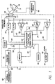
- FIG. 1 sets forth a simplified block diagram of the stimulation device 10.
- the stimulation device 10 is coupled to a heart 5 by way of two leads 12, 14.
- the first lead 12 has at least one electrode 18 in contact with the atrium of the heart 5, and the second lead 14 has at least one electrode 20 in contact with the ventricles of the heart 5.
- the leads 12, 14 are electrically and physically connected to the stimulation device 10 through a connector 16 which forms an integral part of the housing (not shown) in which the circuits of the stimulation device 10 are housed.
- the connector 16 electrically protects circuits within the stimulation device 10 via a protection network 17 from excessive shocks or voltages that could appear on electrodes 18, 20 in the event with contact with a high voltage signal, e.g., from a defibrillator shock.
- the leads 12, 14 carry the stimulating pulses to the electrodes 18, 20 from an atrial pulse generator 22 and a ventricular pulse generator 24, respectively. Further, the electrical signals from the atrium are carried from electrode 18 through the lead 12 to the input terminal of an atrial channel sense amplifier 26. The electrical signals from the ventricle are carried from the electrode 20 through the lead 14 to the input terminal of the ventricular channel sense amplifier 28. Similarly, electrical signals from both the atrium and ventricle are applied to the inputs of the IEGM (intracardiac electrogram) amplifier 30.
- the stimulation device 10 detects an evoked response from the heart in response to an applied stimulus, allowing the detection of capture with a suitable broad bandpass fitter,
- the IEGM amplifier 30 is also used during transmission to the external programmer's 60 state machine or other control logic.
- the stimulation device 10 is controlled by a controller 32 that typically includes a microprocessor to carrying out the control and timing functions.
- the controller 32 receives output signals from the atrial amplifier 26, the ventricular amplifier 28, and the IEGM amplifier 30 over the signal lines 34, 36, 38, respectively.
- the controller 32 also generates trigger signals that are sent to the atrial pulse generator 22 and the ventricular pulse generator 24 over the signal lines 40, 42, respectively.
- the stimulation device 10 also includes a memory circuit 48 that is coupled to a control system 32 over a suitable data/address bus 50.
- This memory circuit 48 allows certain control parameters, used by the controller 32 in controlling the operation of the stimulation device 10, to be stored and modified, as required, in order to customize the stimulation device's operation to suit the needs of a particular patient. Further, the data sensed by the IEGM amplifier 30 during the operation of the stimulation device 10 may be stored in the memory circuit 48 for later retrieval and analysis.
- a clock circuit 52 directs appropriate clock signal(s) to the controller 32 as well as any other circuits throughout the stimulation device 10, e.g., to the memory circuit 48, by the clock bus 54.
- the stimulation device 10 also includes a telemetry communications circuit 56 which is connected to the controller 32 by way of a suitable command/data bus 58.
- the telemetry circuit 56 is selectively coupled to an external programming device 60 by an appropriate communication link 62 such as any suitable electromagnetic link.
- desired commands may be sent to the control system 32.
- Other data measured within or by the stimulation device 10 such as IEGM data, etc. may be stored and uploaded to the programmer 60.
- the stimulation device 10 additionally includes a battery 64 which provides operating power to all the circuits of the stimulation device 10 via a POWER signal line 66.
- the stimulation device 10 also includes a sensor 68 that is connected to the controller 32 over a suitable connection line 72.
- this sensor detects patient activity via an AC accelerometer, but could be any appropriate sensor which can indicate patient activity. Attention is directed to US 5 476 483 for further examples of other suitable activity sensors.
- any sensor which indicates metabolic need over time could be used in place of the activity sensor.
- Such sensors could be an oxygen saturation sensor, temperature sensor, etc.. In the case of these alternative sensors, the sensor would be placed on the lead 14 as shown by alternative sensor 69.
- the operation of the above described stimulation device 10 is similar to the conventional manner to provide pacing pulses at a rate that comfortably meets the patients metabolic demands.
- the controller 32 uses signals generated by the sensor 68 to determine the activity level of the patient The measured level of activity is indicative of metabolic need. Many methods of determining the activity level are well known in the art Attention is drawn to US 5 476 483.
- the controller 32 To regulate the pacing rate, the controller 32 provides a trigger signal to the A-pulse generator 22 and/or the V-pulse generator 24. The timing of this signal (to a large extent) is determined by the activity level.
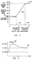
- the activity indicated rate and the circadian base rate methods are illustrated together via a single transfer function.
- the transfer function is used by the control system to correlate the activity level measurements shown along the horizontal axis to the activity indicated pacing rates shown along the vertical axis.
- the controller 32 then triggers the appropriate pulse generator 22, 24 at the activity indicated rate.
- an appropriate transfer function can be used based upon individual patient need.
- different modes of pacing i.e. DDD, VVI, etc.
- Two activity levels are noted on the horizontal axis of the transfer function: a low activity threshold 202 and a high activity threshold 204.
- the pacing rate is maintained at a maximum pacing rate 200.
- the activity indicated pacing rate varies according to the programmed transfer function 208. In this case, the activity indicated pacing rate varies linearly between a circadian base rate 210 and a maximum pacing rate 200.
- this transition can be programmed to meet patient's needs by the physician or adjusted by the processor periodically as set forth in U.S. Patent No. 5,514,162 to Bornzin et al, entitled "System and Method for Automatically Determining the Slope of a Transfer Function for a Rate-Responsive Cardiac Pacemaker", issued May 7, 1996.
- the processor sets the pacing rate to a rate defined by the circadian base rate 210.
- the circadian base rate 210 is defined through monitoring the activity variance measurements as described more fully in US 5 476 483. A patient's activity levels are monitored and activity variance measurements are calculated and monitored to determine when and how long a patient typically sleeps. These two terms are used to define a stimulation rate which is below the programmed base rate of the stimulation device 10 such that the patient receives a lower pacing rate during sleep. This lower pacing rate more closely mimics the natural cardiac rhythm.
- the patient group which suffers from long term diabetes tends to develop neuropathy from the long term exposure of their nerves to excessive blood sugar levels.
- This condition erodes the ability to adequately control the heart rate.
- this condition render the patient unable to compensate for the dramatic drop in blood pressure upon standing after sitting or tying down due to an inability to increase the heart rate and constrict the system resistance and capacitance vessels.
- the controller 32 compensates for the change in patient position by triggering at an orthostatic compensation pacing rate.
- FIG. 3 sets forth the normal heart response to provide the orthostatic compensation.
- the normal autonomic nervous system Upon standing after a prolonged period of sitting or lying down, the normal autonomic nervous system abruptly increases the natural heart rate to approximately 80 - 100 bpm in 3 - 8 seconds at 302. Then, the natural heart rate then slowly decreases to a rest rate in 2 seconds to one minute, typically approximately 60 - 70 bpm at 304.
- FIG. 4 sets forth the orthostatic compensation pacing method that provides the orthostatic compensation to a patient that does not naturally have it.
- the controller 32 abruptly increases the stimulation rate to approximately 85 - 100 bpm in 8 seconds at 402.
- the upper orthostatic compensation pacing rate is determined by the clinician for each individual patient.
- the stimulation rate is slowly decreased to a high base rate in 20 - 60 seconds, typically approximately 70 bpm at 404.
- the controller can override the orthostatic compensation pacing method if the patient activity level indicates an immediate stimulation rate higher than that of the immediate orthostatic compensation pacing rate.
- the controller 32 uses the transfer function 208 as set forth in FIG. 2 to determine the immediate stimulation rate.
- the controller 32 uses the activity level signals and the activity variance measurements to determine when the patient has stood after prolonged time of sitting or lying down.
- the controller 32 monitors two main variables in relation to two preset thresholds: the immediate activity level and the long term variance in activity (also known as the activity variance measurement).
- the clinician programs the activity threshold for a patient appropriate activity level.
- the activity variance threshold is predetermined based upon the patients activity.
- the activity variance measurements are stored in a histogram for a week. Further information regarding histograms can be found in US 5 476 483.
- a night time activity variance threshold and a day time activity variance threshold are determined.
- the night time activity variance threshold is predetermined to be the bins of the histogram which contain counts of less than 17.5% of the total histogram counts.
- the day time activity variance is predetermined to be the bins in the histogram which contains counts of less than 67.5% of the total bin count.
- T rest(expired) is the necessary time for a patient to be resting and then in need of orthostatic compensation once the patient stands. It has been found that a T rest(expired) time duration of 1 minute to 3 hours as programmed by the clinician is the time duration that adequately indicates when a patient will require orthostatic compensation pacing upon standing.
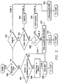
- FIG. 5 sets forth the flow chart describing how the controller 32 determines the immediate pacing rate and if patient has changed body positions and has previously been sitting or lying down for an extended period of time.
- the controller 32 determines if the activity level signal is less than an activity threshold (Block 502), and if the activity variance measurement is greater than an activity variance threshold (Block 504). If these conditions are met, then the patient must be inactive, and the controller 32 adjusts the pacing rate to follow the circadian base rate (Block 506) as set forth in FIG. 2 .
- the controller 32 determines if the activity level signal is less than the activity threshold (Block 502), and the activity variance is also less than the activity variance threshold (Block 504). If these conditions are met, then the patient must be in a reclined or in a supine/prone position and is resting. At this point, the controller 32 starts a duration timer. This duration timer monitors the time the patient is at an extended period of inactivity (i.e. T rest ) (Block 508). The controller 32 adjusts the stimulation rate to follow the circadian base pacing rate (Block 506) as set forth in FIG. 2 .
- the controller 32 determines if the activity level signal is greater than an activity threshold (Block 502) and if the T rest duration timer has been started (Block 520) but has not exceeded T rest(expired) (Block 524). If these conditions are meet, then the patient has been resting a short period of time and has stood. In this case, the controller resets the T rest duration timer (Block 526) and adjusts the pacing rate to the maximum of the activity indicated pacing and the circadian base pacing rate as set forth by the transfer function 208 (Block 522).
- the controller 32 determines if the activity level signal is greater than an activity threshold (Block 502), and the T rest duration timer is greater than the T rest(expired) duration (Blocks 520, 524). If these conditions are met, then the patient must have just stood and is in need of orthostatic compensation pacing.
- the orthostatic compensation pacing method has a total regimen time (N) 406, and the controller 32 starts a regimen duration timer to monitor how far into the orthostatic compensation pacing method the patient is (K) 408.
- the controller determines if the activity level signal is greater than an activity threshold (Block 502), the T rest duration timer exceeds T rest(expired) time period(Blocks 520, 524), and the regimen duration timer exceeds the regimen time (K>N) (Block 528). If these conditions are met, then the patient must have just stood and has finished orthostatic compensation pacing. At this point, the controller 32 resets the T rest duration timer and the regimen duration timer (Block 540) and adjusts the stimulation rate to be the maximum of the activity indicated pacing rate and the circadian base rate (Block 522) as set forth in FIG. 2 .
Claims (10)
- Implantierbares Herzstimulationsgerät zum Anpassen einer Schlagrate in Übereinstimmung mit einem orthostatischen Bedürfnis eines Patienten, wobei das Gerät eingerichtet ist, mit wenigsten einer implantierbaren Leitung verbunden zu werden, wobei das Gerät umfasst:einen physiologischen Sensor, der physiologische Parameter wahrnimmt, welche das Bedürfnis eines Patienten nach einem anpassen der Schlagrate anzeigen und der ein physiologisches Signal erzeugt;einen mit wenigsten einer implantierbaren Leitung verbundenen Impulsgenerator, der Stimulationsimpulse erzeugt; undein Steuergerät, das mit dem physiologischen Sensor und dem Impulsgenerator verbunden ist, unddadurch gekennzeichnet ist, dass
das Steuergerät auf dem Empfang von physiologischen Signalen von dem Sensor reagiert, um eine Inaktivitätsperiode zu erkennen, die wenigstens eine vorgegebene Zeitdauer andauert und von einem Aktivitätsniveau gefolgt wird, dass eine zuvor gesetzte Schwelle überschreitet, und in Reaktion auf dieses Erkennen den Impulsgenerator auf eine orthostatische Ausgleichsschlagrate steuert. - Implantierbares Stimulationsgerät nach Anspruch 1, wobei:das orthostatische Bedürfnis ist, wenn der Patient nach einer ausgedehnten Ruhephase steht; unddie orthostatische Kompensationschlagrate rasches Erhöhen der Schlagrate und langsames Absenken der Schlagrate umfasst.
- Implantierbares Stimulationsgerät nach Anspruch 2, wobei die orthostatische Kompensationsschlagrate Erhöhen der Schlagrate auf ungefähr 80-100 Schläge pro Minute und langsames Absenken der Rate über einen Zeitraum umfasst.
- Implantierbares Stimulationsgerät nach Anspruch 3, wobei das orthostatische Bedürfnis aus den physiologischen Signalen bestimmt wird.
- Implantierbares Stimulationsgerät nach Anspruch 4, wobei
das orthostatische Bedürfnis aus den physiologischen Signalen so bestimmt wird, dass das Steuergerät ausgestaltet ist, aus den physiologischen Signalen ein Aktivitätsniveau eines Patienten und eine Messung der Schwankung der Aktivität eines Patienten zu bestimmen; und
das Steuergerät weiterhin ausgestaltet ist, dass Bedürfnis nach einem orthostatischen Kompensationsschritt zu bestimmen, wenn die Messung der Schwankung der Aktivität eines Patienten für einen vorgegebenen Zeitraum unterhalb einer ersten Schwelle ist und dann das Aktivitätsniveau des Patienten über einer zweiten Schwelle ist. - Implantierbares Stimulationsgerät nach Anspruch 1, wobei der physiologische Sensor ein Aktivitätssensor, vorzugsweise ein AC Beschleunigungsmesser ist.
- Implantierbares Stimulationsgerät nach Anspruch 1, wobei der physiologische Sensor ein Luftsättigungssensor oder ein Impedanzsensor, IEGM oder ein Sensor der evozierten Reaktion ist.
- Implantierbares Stimulationsgerät nach Anspruch 1, wobei das Steuergerät weiterhin ausgestaltet ist, Schrittmachimpulse in einer Schlaggeschwindigkeit, wie sie von den physiologischen Signalen bestimmt wird, auszulösen, wenn der Patient nicht in einem orthostatischen Bedürfnis ist.
- Implantierbares Stimulationsgerät nach Anspruch 8, wobei das Steuergerät weiterhin ausgebildet ist, eine metabolisch indizierte Schlagrate zu bestimmen und Schlagimpulse mit der metabolisch indizierten Schlagrate auszulösen.
- Implantierbares Stimulationsgerät nach Anspruch 9, wobei:die metabolisch indizierte Schlagrate aus einer Aktivität anzeigende Rate oder einer zyklischen Basisrate bestimmt wird:wobei das Steuergerät die von der Aktivität indizierte Rate aus dem Signal des Aktivitätsniveau des Patienten und der zyklischen Basisrate bestimmt, die von dem Signal des Aktivitätsniveaus des Patienten und den Messungen der Aktivitätsschwankung bestimmt werden;
wobei das Steuergerät den Impulsgenerator mit einer Schlagrate auslöst, die gleich dem Maximum von einer orthostatischen Kompensationsschlagrate, der von der Aktivität indizierten Rate und der zyklischen Basisrate ist, wenn der Patient orthostatischer Kompensation bedarf; und
wobei das Steuergerät den Impulsgenerator mit einer Schlagrate auslöst, die gleich dem Maximum von der durch Aktivität indizierten Rate und der zyklischen Basisrate ist, wenn der Patient keiner orthostatischen Kompensation bedarf.
Applications Claiming Priority (2)
| Application Number | Priority Date | Filing Date | Title |
|---|---|---|---|
| US359025 | 1989-05-30 | ||
| US09/359,025 US6351672B1 (en) | 1999-07-22 | 1999-07-22 | System and method for modulating the pacing rate based on patient activity and position |
Publications (3)
| Publication Number | Publication Date |
|---|---|
| EP1070516A2 EP1070516A2 (de) | 2001-01-24 |
| EP1070516A3 EP1070516A3 (de) | 2004-02-04 |
| EP1070516B1 true EP1070516B1 (de) | 2007-05-30 |
Family
ID=23412007
Family Applications (1)
| Application Number | Title | Priority Date | Filing Date |
|---|---|---|---|
| EP00304817A Expired - Lifetime EP1070516B1 (de) | 1999-07-22 | 2000-06-07 | System zum Modulieren der Stimulationsfrequenz basierend auf Aktivität und Körperhaltung des Patienten |
Country Status (3)
| Country | Link |
|---|---|
| US (2) | US6351672B1 (de) |
| EP (1) | EP1070516B1 (de) |
| DE (1) | DE60035000T2 (de) |
Families Citing this family (72)
| Publication number | Priority date | Publication date | Assignee | Title |
|---|---|---|---|---|
| US6351672B1 (en) * | 1999-07-22 | 2002-02-26 | Pacesetter, Inc. | System and method for modulating the pacing rate based on patient activity and position |
| US6456882B1 (en) * | 2000-05-15 | 2002-09-24 | Pacesetter, Inc. | Implantable cardiac stimulation device having automatic capture/threshold capability using a dynamically adjustable safety margin |
| US6647295B2 (en) * | 2000-05-15 | 2003-11-11 | Pacesetter, Inc. | Implantable cardiac stimulation device with detection and therapy for patients with vasovagal syncope |
| US6625492B2 (en) | 2000-05-15 | 2003-09-23 | Pacesetter, Inc. | Implantable cardiac stimulation device with detection and therapy for patients with vasovagal syncope |
| US7340303B2 (en) * | 2001-09-25 | 2008-03-04 | Cardiac Pacemakers, Inc. | Evoked response sensing for ischemia detection |
| MXPA04011059A (es) * | 2002-05-09 | 2005-07-14 | Daemen College | Unidad de estimulacion electrica y sistema de bano maria. |
| US7972275B2 (en) | 2002-12-30 | 2011-07-05 | Cardiac Pacemakers, Inc. | Method and apparatus for monitoring of diastolic hemodynamics |
| US7136704B2 (en) | 2003-04-16 | 2006-11-14 | Alfred E. Mann Foundation For Scientific Research | Blood oxygen monitoring system and a lead therefor |
| US7320675B2 (en) | 2003-08-21 | 2008-01-22 | Cardiac Pacemakers, Inc. | Method and apparatus for modulating cellular metabolism during post-ischemia or heart failure |
| US8396565B2 (en) * | 2003-09-15 | 2013-03-12 | Medtronic, Inc. | Automatic therapy adjustments |
| US7248923B2 (en) | 2003-11-06 | 2007-07-24 | Cardiac Pacemakers, Inc. | Dual-use sensor for rate responsive pacing and heart sound monitoring |
| US6964641B2 (en) * | 2003-12-24 | 2005-11-15 | Medtronic, Inc. | Implantable medical device with sleep disordered breathing monitoring |
| US7171270B1 (en) | 2003-12-29 | 2007-01-30 | Pacesetter, Inc. | Implantable cardiac device to promote intrinsic rhythm to alleviate orthostatic hypotension |
| US7330760B2 (en) * | 2004-03-16 | 2008-02-12 | Medtronic, Inc. | Collecting posture information to evaluate therapy |
| US7881798B2 (en) | 2004-03-16 | 2011-02-01 | Medtronic Inc. | Controlling therapy based on sleep quality |
| WO2005089646A1 (en) * | 2004-03-16 | 2005-09-29 | Medtronic, Inc. | Sensitivity analysis for selecting therapy parameter sets |
| US8055348B2 (en) * | 2004-03-16 | 2011-11-08 | Medtronic, Inc. | Detecting sleep to evaluate therapy |
| US7805196B2 (en) | 2004-03-16 | 2010-09-28 | Medtronic, Inc. | Collecting activity information to evaluate therapy |
| US7395113B2 (en) | 2004-03-16 | 2008-07-01 | Medtronic, Inc. | Collecting activity information to evaluate therapy |
| US7717848B2 (en) | 2004-03-16 | 2010-05-18 | Medtronic, Inc. | Collecting sleep quality information via a medical device |
| US7366572B2 (en) * | 2004-03-16 | 2008-04-29 | Medtronic, Inc. | Controlling therapy based on sleep quality |
| US8725244B2 (en) | 2004-03-16 | 2014-05-13 | Medtronic, Inc. | Determination of sleep quality for neurological disorders |
| US7491181B2 (en) * | 2004-03-16 | 2009-02-17 | Medtronic, Inc. | Collecting activity and sleep quality information via a medical device |
| US8308661B2 (en) * | 2004-03-16 | 2012-11-13 | Medtronic, Inc. | Collecting activity and sleep quality information via a medical device |
| US20050209512A1 (en) * | 2004-03-16 | 2005-09-22 | Heruth Kenneth T | Detecting sleep |
| US20070276439A1 (en) * | 2004-03-16 | 2007-11-29 | Medtronic, Inc. | Collecting sleep quality information via a medical device |
| US7792583B2 (en) * | 2004-03-16 | 2010-09-07 | Medtronic, Inc. | Collecting posture information to evaluate therapy |
| EP1755734B1 (de) * | 2004-04-14 | 2013-02-27 | Medtronic Inc. | Sammeln von haltungs- und aktivitätsinformationen zur beurteilung einer therapie |
| US8135473B2 (en) | 2004-04-14 | 2012-03-13 | Medtronic, Inc. | Collecting posture and activity information to evaluate therapy |
| US7548785B2 (en) | 2004-06-10 | 2009-06-16 | Pacesetter, Inc. | Collecting and analyzing sensed information as a trend of heart failure progression or regression |
| US7559901B2 (en) * | 2004-07-28 | 2009-07-14 | Cardiac Pacemakers, Inc. | Determining a patient's posture from mechanical vibrations of the heart |
| US7269458B2 (en) | 2004-08-09 | 2007-09-11 | Cardiac Pacemakers, Inc. | Cardiopulmonary functional status assessment via heart rate response detection by implantable cardiac device |
| US7389143B2 (en) | 2004-08-12 | 2008-06-17 | Cardiac Pacemakers, Inc. | Cardiopulmonary functional status assessment via metabolic response detection by implantable cardiac device |
| US7662104B2 (en) | 2005-01-18 | 2010-02-16 | Cardiac Pacemakers, Inc. | Method for correction of posture dependence on heart sounds |
| US7424321B2 (en) * | 2005-05-24 | 2008-09-09 | Cardiac Pacemakers, Inc. | Systems and methods for multi-axis cardiac vibration measurements |
| US8021299B2 (en) * | 2005-06-01 | 2011-09-20 | Medtronic, Inc. | Correlating a non-polysomnographic physiological parameter set with sleep states |
| US7922669B2 (en) | 2005-06-08 | 2011-04-12 | Cardiac Pacemakers, Inc. | Ischemia detection using a heart sound sensor |
| US20070021678A1 (en) * | 2005-07-19 | 2007-01-25 | Cardiac Pacemakers, Inc. | Methods and apparatus for monitoring physiological responses to steady state activity |
| US8108034B2 (en) | 2005-11-28 | 2012-01-31 | Cardiac Pacemakers, Inc. | Systems and methods for valvular regurgitation detection |
| US7957809B2 (en) | 2005-12-02 | 2011-06-07 | Medtronic, Inc. | Closed-loop therapy adjustment |
| US8016776B2 (en) * | 2005-12-02 | 2011-09-13 | Medtronic, Inc. | Wearable ambulatory data recorder |
| US7848811B2 (en) * | 2005-12-21 | 2010-12-07 | Cardiac Pacemakers, Inc. | Posture sensor |
| EP1998849B1 (de) * | 2006-03-24 | 2014-12-24 | Medtronic, Inc. | Sammlung von ganginformationen zur beurteilung und kontrolle einer therapie |
| US7780606B2 (en) * | 2006-03-29 | 2010-08-24 | Cardiac Pacemakers, Inc. | Hemodynamic stability assessment based on heart sounds |
| US8000780B2 (en) * | 2006-06-27 | 2011-08-16 | Cardiac Pacemakers, Inc. | Detection of myocardial ischemia from the time sequence of implanted sensor measurements |
| US8343049B2 (en) * | 2006-08-24 | 2013-01-01 | Cardiac Pacemakers, Inc. | Physiological response to posture change |
| US7736319B2 (en) * | 2007-01-19 | 2010-06-15 | Cardiac Pacemakers, Inc. | Ischemia detection using heart sound timing |
| EP2285445B1 (de) | 2008-05-08 | 2014-04-23 | Cardiac Pacemakers, Inc. | Berechnete verzögerungen für eine intermittierende stresstherapie |
| US8583252B2 (en) * | 2008-07-11 | 2013-11-12 | Medtronic, Inc. | Patient interaction with posture-responsive therapy |
| US8504150B2 (en) | 2008-07-11 | 2013-08-06 | Medtronic, Inc. | Associating therapy adjustments with posture states using a stability timer |
| US8708934B2 (en) * | 2008-07-11 | 2014-04-29 | Medtronic, Inc. | Reorientation of patient posture states for posture-responsive therapy |
| US9050471B2 (en) | 2008-07-11 | 2015-06-09 | Medtronic, Inc. | Posture state display on medical device user interface |
| US8150531B2 (en) * | 2008-07-11 | 2012-04-03 | Medtronic, Inc. | Associating therapy adjustments with patient posture states |
| US9327129B2 (en) * | 2008-07-11 | 2016-05-03 | Medtronic, Inc. | Blended posture state classification and therapy delivery |
| US8323218B2 (en) | 2008-07-11 | 2012-12-04 | Medtronic, Inc. | Generation of proportional posture information over multiple time intervals |
| US8401666B2 (en) | 2008-07-11 | 2013-03-19 | Medtronic, Inc. | Modification profiles for posture-responsive therapy |
| US8755901B2 (en) * | 2008-07-11 | 2014-06-17 | Medtronic, Inc. | Patient assignment of therapy parameter to posture state |
| US8280517B2 (en) | 2008-09-19 | 2012-10-02 | Medtronic, Inc. | Automatic validation techniques for validating operation of medical devices |
| US20100324611A1 (en) * | 2008-12-10 | 2010-12-23 | Waverx, Inc. | Devices, systems and methods for preventing and treating sensation loss |
| US9026223B2 (en) | 2009-04-30 | 2015-05-05 | Medtronic, Inc. | Therapy system including multiple posture sensors |
| US8175720B2 (en) | 2009-04-30 | 2012-05-08 | Medtronic, Inc. | Posture-responsive therapy control based on patient input |
| US9327070B2 (en) * | 2009-04-30 | 2016-05-03 | Medtronic, Inc. | Medical device therapy based on posture and timing |
| US9956418B2 (en) | 2010-01-08 | 2018-05-01 | Medtronic, Inc. | Graphical manipulation of posture zones for posture-responsive therapy |
| US9357949B2 (en) | 2010-01-08 | 2016-06-07 | Medtronic, Inc. | User interface that displays medical therapy and posture data |
| US8579834B2 (en) | 2010-01-08 | 2013-11-12 | Medtronic, Inc. | Display of detected patient posture state |
| US9149210B2 (en) * | 2010-01-08 | 2015-10-06 | Medtronic, Inc. | Automated calibration of posture state classification for a medical device |
| US9566441B2 (en) | 2010-04-30 | 2017-02-14 | Medtronic, Inc. | Detecting posture sensor signal shift or drift in medical devices |
| US8433419B2 (en) | 2010-10-13 | 2013-04-30 | Cardiac Pacemakers, Inc. | Method and apparatus for controlling neurostimulation according to physical state |
| US9907959B2 (en) | 2012-04-12 | 2018-03-06 | Medtronic, Inc. | Velocity detection for posture-responsive therapy |
| US9737719B2 (en) | 2012-04-26 | 2017-08-22 | Medtronic, Inc. | Adjustment of therapy based on acceleration |
| CN108136189B (zh) * | 2015-08-28 | 2021-10-15 | 心脏起搏器股份公司 | 用于行为响应信号检测和治疗递送的系统 |
| US11596795B2 (en) | 2017-07-31 | 2023-03-07 | Medtronic, Inc. | Therapeutic electrical stimulation therapy for patient gait freeze |
Family Cites Families (14)
| Publication number | Priority date | Publication date | Assignee | Title |
|---|---|---|---|---|
| US5074302A (en) | 1989-01-25 | 1991-12-24 | Siemens-Pacesetter, Inc. | Self-adjusting rate-responsive pacemaker and method thereof |
| US5040536A (en) * | 1990-01-31 | 1991-08-20 | Medtronic, Inc. | Intravascular pressure posture detector |
| FR2685642B1 (fr) | 1991-12-31 | 1996-09-13 | Ela Medical Sa | Stimulateur cardiaque a frequence asservie a l'effort du patient. |
| US5354317A (en) | 1992-04-03 | 1994-10-11 | Intermedics, Inc. | Apparatus and method for cardiac pacing responsive to patient position |
| US5342404A (en) | 1992-04-03 | 1994-08-30 | Intermedics, Inc. | Implantable medical interventional device |
| US5282839A (en) * | 1992-12-14 | 1994-02-01 | Medtronic, Inc. | Rate responsive cardiac pacemaker and method for providing an optimized pacing rate which varies with a patient's physiologic demand |
| US5514162A (en) | 1994-06-07 | 1996-05-07 | Pacesetter, Inc. | System and method for automatically determining the slope of a transfer function for a rate-responsive cardiac pacemaker |
| US5476483A (en) | 1994-06-10 | 1995-12-19 | Pacesetter, Inc. | System and method for modulating the base rate during sleep for a rate-responsive cardiac pacemaker |
| US5725562A (en) | 1995-03-30 | 1998-03-10 | Medtronic Inc | Rate responsive cardiac pacemaker and method for discriminating stair climbing from other activities |
| US5593431A (en) | 1995-03-30 | 1997-01-14 | Medtronic, Inc. | Medical service employing multiple DC accelerometers for patient activity and posture sensing and method |
| US5891176A (en) * | 1996-05-09 | 1999-04-06 | Pacesetter, Inc. | System and method for providing hemodynamically optimal pacing |
| US5733312A (en) | 1997-01-17 | 1998-03-31 | Pacesetter, Inc. | System and method for modulating the output of an implantable medical device in response to circadian variations |
| US6044297A (en) * | 1998-09-25 | 2000-03-28 | Medtronic, Inc. | Posture and device orientation and calibration for implantable medical devices |
| US6351672B1 (en) * | 1999-07-22 | 2002-02-26 | Pacesetter, Inc. | System and method for modulating the pacing rate based on patient activity and position |
-
1999
- 1999-07-22 US US09/359,025 patent/US6351672B1/en not_active Expired - Lifetime
-
2000
- 2000-06-07 DE DE60035000T patent/DE60035000T2/de not_active Expired - Lifetime
- 2000-06-07 EP EP00304817A patent/EP1070516B1/de not_active Expired - Lifetime
-
2001
- 2001-10-25 US US10/032,793 patent/US7225023B1/en not_active Expired - Lifetime
Also Published As
| Publication number | Publication date |
|---|---|
| DE60035000D1 (de) | 2007-07-12 |
| US7225023B1 (en) | 2007-05-29 |
| DE60035000T2 (de) | 2008-01-31 |
| EP1070516A2 (de) | 2001-01-24 |
| EP1070516A3 (de) | 2004-02-04 |
| US6351672B1 (en) | 2002-02-26 |
Similar Documents
| Publication | Publication Date | Title |
|---|---|---|
| EP1070516B1 (de) | System zum Modulieren der Stimulationsfrequenz basierend auf Aktivität und Körperhaltung des Patienten | |
| CA2184495C (en) | Method and apparatus for dual chamber cardiac pacing | |
| US6466821B1 (en) | AC/DC multi-axis accelerometer for determining patient activity and body position | |
| US7212862B2 (en) | Cardiac stimulation device including sleep apnea prevention and treatment | |
| US6999817B2 (en) | Cardiac stimulation device including sleep apnea prevention and treatment | |
| US7869877B2 (en) | Cardiopulmonary functional status assessment via heart rate response detection by implantable cardiac device | |
| AU661416B2 (en) | Automatic cardiac capture restoration and threshold-seeking apparatus | |
| US7179229B1 (en) | System and method for apnea detection using blood pressure detected via an implantable medical system | |
| US7225021B1 (en) | Differentiation of central sleep apnea and obstructive sleep apnea using an implantable cardiac device | |
| US8412326B2 (en) | Pacemaker with vagal surge monitoring and response | |
| US5447525A (en) | Pacemaker which adapts to minimize current drain and provide desired capture safety margin | |
| US8538525B2 (en) | Cardiopulmonary functional status assessment via metabolic response detection by implantable cardiac device | |
| EP0431437B1 (de) | System und Verfahren zur Erhaltung der Reizimpulsamplitude bei Batterienentladung mittels selbstregulierender Stromaufnahme | |
| US6510342B1 (en) | Methods and apparatus for preventing atrial arrhythmias by overdrive pacing multiple heart tissue sites using an implantable cardiac stimulation device | |
| WO2002072195A2 (en) | Rate adaptive pacemaker system with dual sensing component and method of using same | |
| JP2005515043A (ja) | 失神を検出し処置する方法および装置 | |
| US7142920B2 (en) | Chronotropic status monitor for implantable cardiac device | |
| US5127402A (en) | System and method for maintaining stimulation pulse amplitude at battery depletion by self-regulating current drain usage | |
| US5228439A (en) | System and method for maintaining proper device operation at battery depletion by self-regulating current drain usage | |
| US7706881B1 (en) | Implantable medical device with cardiac output- based apnea suppression |
Legal Events
| Date | Code | Title | Description |
|---|---|---|---|
| PUAI | Public reference made under article 153(3) epc to a published international application that has entered the european phase |
Free format text: ORIGINAL CODE: 0009012 |
|
| AK | Designated contracting states |
Kind code of ref document: A2 Designated state(s): AT BE CH CY DE DK ES FI FR GB GR IE IT LI LU MC NL PT SE |
|
| AX | Request for extension of the european patent |
Free format text: AL;LT;LV;MK;RO;SI |
|
| PUAL | Search report despatched |
Free format text: ORIGINAL CODE: 0009013 |
|
| AK | Designated contracting states |
Kind code of ref document: A3 Designated state(s): AT BE CH CY DE DK ES FI FR GB GR IE IT LI LU MC NL PT SE |
|
| AX | Request for extension of the european patent |
Extension state: AL LT LV MK RO SI |
|
| RIC1 | Information provided on ipc code assigned before grant |
Ipc: 7A 61N 1/365 A Ipc: 7A 61N 1/37 B |
|
| 17P | Request for examination filed |
Effective date: 20040611 |
|
| AKX | Designation fees paid |
Designated state(s): CH DE FR IE IT LI |
|
| 17Q | First examination report despatched |
Effective date: 20050329 |
|
| GRAP | Despatch of communication of intention to grant a patent |
Free format text: ORIGINAL CODE: EPIDOSNIGR1 |
|
| RTI1 | Title (correction) |
Free format text: SYSTEM FOR MODULATING THE PACING RATE BASED ON PATIENT ACTIVITY AND POSITION |
|
| GRAS | Grant fee paid |
Free format text: ORIGINAL CODE: EPIDOSNIGR3 |
|
| GRAA | (expected) grant |
Free format text: ORIGINAL CODE: 0009210 |
|
| AK | Designated contracting states |
Kind code of ref document: B1 Designated state(s): CH DE FR IE IT LI |
|
| REG | Reference to a national code |
Ref country code: CH Ref legal event code: EP |
|
| REG | Reference to a national code |
Ref country code: IE Ref legal event code: FG4D |
|
| REF | Corresponds to: |
Ref document number: 60035000 Country of ref document: DE Date of ref document: 20070712 Kind code of ref document: P |
|
| REG | Reference to a national code |
Ref country code: CH Ref legal event code: NV Representative=s name: KIRKER & CIE S.A. |
|
| ET | Fr: translation filed | ||
| PLBE | No opposition filed within time limit |
Free format text: ORIGINAL CODE: 0009261 |
|
| STAA | Information on the status of an ep patent application or granted ep patent |
Free format text: STATUS: NO OPPOSITION FILED WITHIN TIME LIMIT |
|
| 26N | No opposition filed |
Effective date: 20080303 |
|
| PG25 | Lapsed in a contracting state [announced via postgrant information from national office to epo] |
Ref country code: IE Free format text: LAPSE BECAUSE OF NON-PAYMENT OF DUE FEES Effective date: 20070607 |
|
| PGFP | Annual fee paid to national office [announced via postgrant information from national office to epo] |
Ref country code: CH Payment date: 20120625 Year of fee payment: 13 |
|
| PGFP | Annual fee paid to national office [announced via postgrant information from national office to epo] |
Ref country code: FR Payment date: 20120705 Year of fee payment: 13 |
|
| PGFP | Annual fee paid to national office [announced via postgrant information from national office to epo] |
Ref country code: IT Payment date: 20120622 Year of fee payment: 13 |
|
| PGFP | Annual fee paid to national office [announced via postgrant information from national office to epo] |
Ref country code: DE Payment date: 20130627 Year of fee payment: 14 |
|
| REG | Reference to a national code |
Ref country code: CH Ref legal event code: PL |
|
| REG | Reference to a national code |
Ref country code: FR Ref legal event code: ST Effective date: 20140228 |
|
| PG25 | Lapsed in a contracting state [announced via postgrant information from national office to epo] |
Ref country code: LI Free format text: LAPSE BECAUSE OF NON-PAYMENT OF DUE FEES Effective date: 20130630 Ref country code: CH Free format text: LAPSE BECAUSE OF NON-PAYMENT OF DUE FEES Effective date: 20130630 |
|
| PG25 | Lapsed in a contracting state [announced via postgrant information from national office to epo] |
Ref country code: IT Free format text: LAPSE BECAUSE OF NON-PAYMENT OF DUE FEES Effective date: 20130607 Ref country code: FR Free format text: LAPSE BECAUSE OF NON-PAYMENT OF DUE FEES Effective date: 20130701 |
|
| REG | Reference to a national code |
Ref country code: DE Ref legal event code: R119 Ref document number: 60035000 Country of ref document: DE |
|
| REG | Reference to a national code |
Ref country code: DE Ref legal event code: R119 Ref document number: 60035000 Country of ref document: DE Effective date: 20150101 |
|
| PG25 | Lapsed in a contracting state [announced via postgrant information from national office to epo] |
Ref country code: DE Free format text: LAPSE BECAUSE OF NON-PAYMENT OF DUE FEES Effective date: 20150101 |