EP0795952B1 - Verfahren und Vorrichtung zum Anhalten eines Motors mit magnetischen Lagern - Google Patents
Verfahren und Vorrichtung zum Anhalten eines Motors mit magnetischen Lagern Download PDFInfo
- Publication number
- EP0795952B1 EP0795952B1 EP97104282A EP97104282A EP0795952B1 EP 0795952 B1 EP0795952 B1 EP 0795952B1 EP 97104282 A EP97104282 A EP 97104282A EP 97104282 A EP97104282 A EP 97104282A EP 0795952 B1 EP0795952 B1 EP 0795952B1
- Authority
- EP
- European Patent Office
- Prior art keywords
- power supply
- motor
- windings
- magnetic bearings
- electric power
- Prior art date
- Legal status (The legal status is an assumption and is not a legal conclusion. Google has not performed a legal analysis and makes no representation as to the accuracy of the status listed.)
- Expired - Lifetime
Links
- 238000000034 method Methods 0.000 title description 7
- 238000004804 winding Methods 0.000 description 32
- 230000006698 induction Effects 0.000 description 24
- 238000001514 detection method Methods 0.000 description 16
- 230000001276 controlling effect Effects 0.000 description 4
- 238000010586 diagram Methods 0.000 description 3
- 239000004065 semiconductor Substances 0.000 description 3
- 230000001105 regulatory effect Effects 0.000 description 2
- 238000005229 chemical vapour deposition Methods 0.000 description 1
- 230000001419 dependent effect Effects 0.000 description 1
- 230000000694 effects Effects 0.000 description 1
- 239000010687 lubricating oil Substances 0.000 description 1
- 238000012423 maintenance Methods 0.000 description 1
- 238000004519 manufacturing process Methods 0.000 description 1
- 238000012986 modification Methods 0.000 description 1
- 230000004048 modification Effects 0.000 description 1
- 238000011084 recovery Methods 0.000 description 1
- 230000001360 synchronised effect Effects 0.000 description 1
Images


Classifications
-
- H—ELECTRICITY
- H02—GENERATION; CONVERSION OR DISTRIBUTION OF ELECTRIC POWER
- H02J—CIRCUIT ARRANGEMENTS OR SYSTEMS FOR SUPPLYING OR DISTRIBUTING ELECTRIC POWER; SYSTEMS FOR STORING ELECTRIC ENERGY
- H02J9/00—Circuit arrangements for emergency or stand-by power supply, e.g. for emergency lighting
- H02J9/04—Circuit arrangements for emergency or stand-by power supply, e.g. for emergency lighting in which the distribution system is disconnected from the normal source and connected to a standby source
- H02J9/06—Circuit arrangements for emergency or stand-by power supply, e.g. for emergency lighting in which the distribution system is disconnected from the normal source and connected to a standby source with automatic change-over, e.g. UPS systems
- H02J9/062—Circuit arrangements for emergency or stand-by power supply, e.g. for emergency lighting in which the distribution system is disconnected from the normal source and connected to a standby source with automatic change-over, e.g. UPS systems for AC powered loads
-
- F—MECHANICAL ENGINEERING; LIGHTING; HEATING; WEAPONS; BLASTING
- F16—ENGINEERING ELEMENTS AND UNITS; GENERAL MEASURES FOR PRODUCING AND MAINTAINING EFFECTIVE FUNCTIONING OF MACHINES OR INSTALLATIONS; THERMAL INSULATION IN GENERAL
- F16C—SHAFTS; FLEXIBLE SHAFTS; ELEMENTS OR CRANKSHAFT MECHANISMS; ROTARY BODIES OTHER THAN GEARING ELEMENTS; BEARINGS
- F16C32/00—Bearings not otherwise provided for
- F16C32/04—Bearings not otherwise provided for using magnetic or electric supporting means
- F16C32/0406—Magnetic bearings
- F16C32/044—Active magnetic bearings
- F16C32/0442—Active magnetic bearings with devices affected by abnormal, undesired or non-standard conditions such as shock-load, power outage, start-up or touchdown
-
- F—MECHANICAL ENGINEERING; LIGHTING; HEATING; WEAPONS; BLASTING
- F16—ENGINEERING ELEMENTS AND UNITS; GENERAL MEASURES FOR PRODUCING AND MAINTAINING EFFECTIVE FUNCTIONING OF MACHINES OR INSTALLATIONS; THERMAL INSULATION IN GENERAL
- F16C—SHAFTS; FLEXIBLE SHAFTS; ELEMENTS OR CRANKSHAFT MECHANISMS; ROTARY BODIES OTHER THAN GEARING ELEMENTS; BEARINGS
- F16C32/00—Bearings not otherwise provided for
- F16C32/04—Bearings not otherwise provided for using magnetic or electric supporting means
- F16C32/0406—Magnetic bearings
- F16C32/044—Active magnetic bearings
- F16C32/0444—Details of devices to control the actuation of the electromagnets
- F16C32/0457—Details of the power supply to the electromagnets
-
- F—MECHANICAL ENGINEERING; LIGHTING; HEATING; WEAPONS; BLASTING
- F16—ENGINEERING ELEMENTS AND UNITS; GENERAL MEASURES FOR PRODUCING AND MAINTAINING EFFECTIVE FUNCTIONING OF MACHINES OR INSTALLATIONS; THERMAL INSULATION IN GENERAL
- F16C—SHAFTS; FLEXIBLE SHAFTS; ELEMENTS OR CRANKSHAFT MECHANISMS; ROTARY BODIES OTHER THAN GEARING ELEMENTS; BEARINGS
- F16C2360/00—Engines or pumps
- F16C2360/44—Centrifugal pumps
- F16C2360/45—Turbo-molecular pumps
-
- F—MECHANICAL ENGINEERING; LIGHTING; HEATING; WEAPONS; BLASTING
- F16—ENGINEERING ELEMENTS AND UNITS; GENERAL MEASURES FOR PRODUCING AND MAINTAINING EFFECTIVE FUNCTIONING OF MACHINES OR INSTALLATIONS; THERMAL INSULATION IN GENERAL
- F16C—SHAFTS; FLEXIBLE SHAFTS; ELEMENTS OR CRANKSHAFT MECHANISMS; ROTARY BODIES OTHER THAN GEARING ELEMENTS; BEARINGS
- F16C2380/00—Electrical apparatus
- F16C2380/26—Dynamo-electric machines or combinations therewith, e.g. electro-motors and generators
Definitions
- the present invention relates to a method of and an apparatus for stopping a motor having magnetic bearings, and more particularly to a method of and an apparatus for stopping, in case of an emergency such as a power supply failure, a motor whose rotor is rotatably levitated and supported by magnetic bearings out of contact therewith.
- the above-mentioned motor is preferably utilized in a semiconductor manufacturing apparatus such as a spin dryer for semiconductor wafer, and a CVD(chemical Vapor Deposition) apparatus, in which dust-free semiconductor wafer rotation mechanism is adopted.
- the motor is preferably utilized, for example, in rotation mechanism of a turbo-molecular pump, a compressor, a turbine, and a spindle of machine tool.
- Magnetic bearings for levitating and supporting motor rotors out of contact therewith under magnetic attractive forces of electromagnets have recently found widespread use. Motors with their rotors supported by magnetic bearings require no maintenance for the bearings, can rotate at high speeds, and produce reduced noise because the-bearings that are kept out of contact with the rotors are free of wear and do not need lubricating oil.
- Such magnetic bearings are usually equipped with a battery power supply for use in case of emergencies such as a failure of a commercial AC power supply (primary power supply).
- a commercial AC power supply primary power supply
- the battery power supply is switched on to enable the magnetic bearings to continuously operate for levitating and supporting the rotor out of contact therewith.
- a motor whose rotor is rotatably levitated and supported by magnetic bearings is an induction motor
- the windings of the motor are usually supplied with AC power from a frequency/voltage converter such as an inverter or the like which is supplied with three-phase AC power from a three-phase commercial AC power supply.
- the inverter rectifies the three-phase AC power into DC power, then produces AC power from the DC power, and supplies the AC power to the windings of the motor.
- the three-phase commercial AC power supply suffers a failure, it has been customary to switch from the three-phase commercial AC power supply to a battery power supply, which energizes the inverter to continuously operate the induction motor with the AC power supplied therefrom.
- the DC power generated by the inverter from the AC power has a DC voltage which is close to the DC voltage of the battery power supply.
- FIG. 1 of the accompanying drawings shows a conventional apparatus for supplying electric power to a motor which has magnetic bearings.
- a magnetic bearing cable 3 and a motor cable 5 are connected to an induction motor 1 whose rotor is rotatably levitated and supported by magnetic bearings.
- the magnetic bearing cable 3 and the motor cable 5 are connected through a control console 7 to a three-phase, 200-V commercial AC power supply.
- the control console 7 has a magnetic bearing controller 2, connected to the commercial AC power supply, which supplies a magnetic bearing control current through the magnetic bearing cable 3 to control the magnetic bearings which levitate and support the rotor out of contact therewith at a target position.
- the control console 7 also has a motor driver 4 which comprises a frequency/voltage converter such as a general-purpose inverter or the like that is connected to the commercial AC power supply.
- the motor driver 4 supplies electric power having a predetermined frequency/voltage through the motor cable 5 for operating the motor 1 at a predetermined speed.
- the magnetic bearing controller 2 is backed up by a battery power supply (DC power supply) 6 such as a 48-V, 2.2-Ahr battery. When the commercial AC power supply fails, the battery power supply 6 supplies DC power to the magnetic bearing controller 2 to enable the magnetic bearing controller 2 to continuously operate the magnetic bearings.
- DC power supply such as a 48-V, 2.2-Ahr battery.
- the magnetic bearings are continuously operated by the DC power supplied from the battery power supply 6.
- the motor driver 4 is no longer supplied with the AC power from the commercial AC power supply
- the rotor of the induction motor 1 rotates in a free-running condition.
- the rotor which is rotatably supported by the magnetic bearings usually rotates at a high speed of at least several thousands rpm. Because the rotor is magnetically kept out of contact with the magnetic bearings, the rotor does not suffer any friction force or decelerated. Consequently, it takes a long period of time, sometimes several tens minutes, until the rotor comes to a stop. Such continued rotation of the rotor, regardLess of the shutdown of a load of the motor due to the power supply failure, may possibly bring about a secondary accident.
- EP-A-0 430 009 shows an apparatus for supplying electric current to magnetic bearings of a vacuum pump from an auxiliary power supply circuit during failure of a main power supply circuit.
- power from the mains is used to supply electric current to the magnetic bearings and to drive an electric motor, who's own rotor is fixed to the rotor of the pump.
- auxiliary power is conducted by a switch to the bearing to keep the bearings in a levitating state. Further, said auxiliary power is also used to drive the electric motor in order to keep the pump running.
- US-A-4,305,030 shows an electronic motor breaking system for use with an alternating current motor and an AC power source having a power circuit for supplying a DC breaking current to the motor.
- US-A-5,376,867 shows an electronic breaking device for asynchronous motors which are equipped with magnetic bearings.
- the breaking device recovers kinetic energy from the rotor during its deceleration, to convert the kinetic energy to an electric current which is then supplied to the magnetic bearings to continuously operate them.
- a method of stopping a motor having a rotor rotatably supported by magnetic bearings out of contact therewith, the motor having windings normally energizable by electric power from a primary power supply comprising the steps of supplying electric power from a battery power supply to the magnetic bearings to continuously operate the magnetic bearings upon a failure of the primary power supply, disconnecting the primary power supply from the windings of the motor, and supplying electric power from the battery power supply to the windings of the motor thereby to brake the motor.
- the primary power supply is disconnected from the windings and the electric power is supplied from the battery power supply to the windings at respective times controlled by timers.
- the primary power supply is disconnected from the windings and the electric power is supplied from the battery power supply to the windings by a switching controller in response to a signal indicative of the failure of the primary power supply.
- the voltage of the electric power supplied from the battery power supply to the windings is variable by a voltage regulator connected to the battery power supply.
- a method of stopping a motor energizable by a primary power supply upon a failure of the primary power supply, the motor having a rotor rotatably supported by magnetic bearings out of contact therewith which are normally operated by a control current generated from electric power supplied from the primary power supply, comprising the steps of supplying battery power to the magnetic bearings to continuously operate the magnetic bearings, disconnecting the primary power supply from windings of the motor, and supplying battery power to the windings of the motor thereby to brake the motor.
- an apparatus for stopping a motor having a rotor rotatably supported by magnetic bearings out of contact therewith, the motor having windings normally energizable by electric power from a primary power supply comprising a motor driver for energizing the windings of the motor with electric power from the primary power supply, a battery power supply for supplying electric power to the windings of the motor and the magnetic bearings upon a failure of the primary power supply, and a switching controller for controlling times to supply the electric power from the battery power supply to the windings of the motor and the magnetic bearings.
- the switching controller has timers for controlling the times.
- the apparatus also has a detector for detecting the failure of the primary power supply, the switching controller including means for controlling the times in response to a signal from the detector.
- the apparatus further includes a voltage regulator connected to the battery power supply for regulating the voltage of the electric power supplied from the battery power supply to the windings upon the failure of the primary power supply.
- the primary power supply typically a commercial AC power supply
- the electric power from the battery supply is supplied to the windings of the motor. Since a direct current flows through the windings, the windings develop a DC magnetic field which applies braking forces to the rotor. The rotor can thus be brought to a rapid stop in a DC braking mode.
- the supply of the electric power from the battery power supply to the motor windings upon the failure of the primary power supply is controlled by timers. After the rotor has come to a stop, the motor windings are immediately disconnected from the battery power supply, and connected to the primary power supply, without wasting the electric power of the battery power supply. The motor can be started immediately when the primary power supply recovers.
- FIG. 2 shows in block form an apparatus for supplying electric power to a motor having magnetic bearings, to which the present invention is applied.
- the apparatus has a magnetic bearing cable 3 connected between an induction motor 1 and a control console 7, a motor cable 5A connected between the induction motor 1 and a switching controller 10, and a motor cable 5B connected between the switching controller 10 and the control console 7.
- the induction motor 1 has a rotor rotatably levitated and supported magnetically by magnetic bearings out of contact therewith.
- the control console 7 has a magnetic bearing controller 2, connected to a three-phase, 200-V commercial AC power supply, which supplies a magnetic bearing control current through the magnetic bearing cable 3 to control the magnetic bearings which levitate and support the rotor out of contact therewith at a target position.
- the control console 7 also has a motor driver 4 which comprises a frequency/voltage converter such as a general-purpose inverter or the like that is connected to the commercial AC power supply.
- the motor driver 4 is connected to the switching controller 10 by the motor cable 5B.
- the motor driver 4 supplies electric power having a predetermined frequency/voltage for operating the motor 1 at a predetermined speed.
- the magnetic bearing controller 2 is backed up by a battery power supply (DC power supply) 6 such as a 48-V, 2.2-Ahr battery. When the commercial AC power supply fails, the battery power supply 6 supplies DC power to the magnetic bearing controller 2 to enable the magnetic bearing controller 2 to continuously operate the magnetic bearings.
- the battery power supply 6 is also connected to the switching controller 10 by a cable 12.
- a power supply failure detection signal line 11 is connected between the magnetic bearing controller 2 and the switching controller 10.
- a power supply failure detection signal is supplied from the magnetic bearing controller 2 to the switching controller 10 to operate the switching controller 10 to connect the cable 12 to the motor cable 5A.
- the switching controller 10 connects the motor cables 5A, 5B to each other while the commercial AC power supply is in normal operation.
- the magnetic bearing controller 2 While the commercial AC power supply is in normal operation, the magnetic bearing controller 2 generates a control current for controlling the magnetic bearings from the AC power supplied from the commercial AC power supply, and supplies the control current to the magnetic bearings through the magnetic bearing cable 3. Since the switching controller 10 connects the motor cables 5A, 5B to each other, AC power having a converted frequency/voltage generated by the motor driver 4 is supplied through the motor cable 5B, the switching controller 10, and the cable 5A to the windings of the induction motor 1.
- a power supply failure detector 7a sends a power supply failure detection signal to the magnetic bearing controller 2.
- a control box in the magnetic bearing controller 2 switches from the commercial AC power supply to the battery power supply 6 for continuously operating the magnetic bearings.
- the power supply failure detection signal is also sent from the magnetic bearing controller 2 through the power supply failure detection signal line 11 to the switching controller 10.
- the switching controller 10 connects the motor cable 5A to the cable 12 and disconnects the motor cable 5B from the motor cable 5A. Therefore, the DC power from the battery power supply 6 is supplied through the cable 12, the switching controller 10, and the motor cable 5A to the windings of the induction motor 1.
- FIG. 3 shows an internal structure of the switching controller 10.
- the switching controller 10 has switching relays 20, 21.
- the switching relay 20 is of the normally closed type, and the switching relay 21 is of the normally open type.
- the switching relay 20 is closed, i.e., it connects U, V, W terminals of the motor cable 5B to respective U, V, W terminals of the motor cable 5A. Therefore, the AC power from the motor driver 4 is supplied through the motor cable 5B, the switching relay 20, and the motor cable 5A to the windings of the induction motor 1.
- a power supply failure detection signal is applied from the power supply failure detection signal line 11 to a control box 24.
- the control box 24 sends a control signal over a signal line 22 to open the switching relay 20, i.e., to disconnect the U, V, W terminals of the motor cable 5A from the respective U, V, W terminals of the motor cable 5B.
- the switching relay 21 is open while the commercial AC power supply is in normal operation.
- the control box 24 sends a control signal over a signal line 23 to close the switching relay 21, connecting the U, V, W terminals of the motor cable 5A to a voltage regulator 25.
- the voltage regulator 25 is supplied with the DC power from the battery power supply 6 through the cable 12, and increases or reduces the voltage of the supplied DC power to a voltage indicated by the control box 24, and supplies the regulated DC power to the induction motor 1 through the switching relay 21 and the motor cable 5A to the windings of the induction motor 1.
- the induction motor 1 is braked as described later on.
- the voltage regulator 25 has positive and negative output terminals which can be connected respectively to the V and W terminals of the motor cable 5A, the positive terminal being connected through a line 27 to the U terminal of the cable 5A.
- the induction motor 1 can sufficiently be braked even if the line 27 is dispensed with. If the switching controller 10 is to be simplified in its circuit arrangement, then the line 27 may be dispensed with.
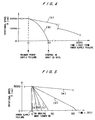
- FIG. 4 is a graph which shows how a motor having magnetic bearings is brought to a stop upon a power supply failure in a conventional free-running mode and a DC braking mode according to the present invention.
- the graph shown in FIG. 4 has a horizontal axis representing time (seconds) which has elapsed from the power supply failure, and a vertical axis representing the rotational speed N (rpm) of the motor.
- the curve (a) shows the manner in which the motor is brought to a stop upon a power supply failure in the conventional free-running mode.
- the curve (b) shows the manner in which the motor is brought to a stop upon a power supply failure in the DC braking mode in which the motor is braked by supplied DC power.
- the free-running mode indicated by the curve (a) since the rotor of the motor is supported by the magnetic bearings out of contact therewith, the rotor is not subjected to frictional or sliding forces which would otherwise be imposed by usual mechanical bearings. Consequently, the rotor rotates in a free-running condition. If the rotational speed of the rotor prior to the power supply failure is about 20000 rpm, for example, then it takes a long period of time, at least 3000 seconds, before the rotor stops. According to the DC braking mode indicated by the curve (b), the windings of the motor are supplied with the DC power when the power supply failure is detected.
- the rotor can be braked to a rapid stop in about 30 seconds from the high-speed rotation, for example, at 20000 rpm.
- FIG. 5 shows how a motor having magnetic bearings is brought to a stop upon a power supply failure in the DC braking mode at various DC voltages.
- the graph shown in FIG. 5 has a horizontal axis representing time (seconds) which has elapsed from the power supply failure, and a vertical axis representing the rotational speed N (rpm) of the motor.
- the power supply failure occurs while the rotor is rotating at a speed of 5000 rpm.
- the rotor is braked to a stop in the DC braking mode according to the curves (a), (b), (c), (d) at the respective DC voltages of 48 V, 36 V, 24 V, 12V which are applied to the windings of the motor.
- FIG. 6 shows in block form a switching timing control unit in the control box 24 in the switching controller 10.
- the switching timing control unit shown in FIG. 6 serves to energize the switching relays 20, 21 shown in FIG. 3.
- the switching timing control unit has an input terminal connected to the power supply failure detection signal line 11.
- the switching timing control unit also has timers 30, 31, 32 which operate in various combinations to open and close the switching relays 20, 21 as described below.
- the timer 30 has an output terminal connected to an input terminal of an AND gate 33 whose output terminal is connected to a relay 34 which is connected to the switching relay 21.
- the timer 31 has an output terminal connected through an inverter 35 to another input terminal of the AND gate 33.
- the timer 32 has an output terminal connected through an inverter 37 to an input terminal of an AND gate 36 whose output terminal is connected to a relay 38 which is connected to the switching relay 20.
- the power supply failure detection signal line 11 is connected to input terminals of the timers 30, 31, 32 and also connected to another input terminal of the AND gate 36.
- FIG. 7 shows a switching timing pattern according to the switching timing control unit shown in FIG. 6.
- a power supply failure detection signal indicated by "H” is inputted from the power supply failure detection signal line 11
- all the timers 30, 31, 32 start measuring time, but remain turned off.
- the power supply failure detection signal and an output signal from the inverter 37 cause the AND gate 36 to apply an output signal to turn on the relay 38, thereby opening the switching relay 20 to disconnect the motor cable 5B from the motor driver 4.
- the timer 30 reaches timeout after the power supply failure detection signal is inputted, the timer 30 is turned on.
- the timer 31 Since the timer 31 still remains turned off, an output signal from the timer 30 and an output signal from the inverter 35 cause the AND gate 33 to apply an output signal to turn on the relay 34, thereby closing the switching relay 21.
- the DC power from the battery power supply 6 is supplied through the voltage regulator 25, the switching relay 21, and the motor cable 5A to the windings of the induction motor 1.
- the induction motor 1 is braked to a rapid stop in the DC braking mode. Since the induction motor 1 can be brought to a stop within about 10 seconds at maximum from the beginning of an emergency such as a power supply failure, the safety of a facility or plant which incorporates the induction motor 1 can be increased.
- the timer 31 When the timer 31 thereafter reaches timeout, it is turned on, turning off the AND gate 33. Therefore, the relay 34 is turned off, opening the switching relay 21 which disconnects the motor cable 5A from the voltage regulator 25. The DC braking mode is canceled.
- the timer 31 may be turned on before reaching a perfect stop of the motor.
- the timer 32 When the timer 32 subsequently reaches timeout, it is turned on, turning off the relay 38 which closes the switching relay 20.
- the motor cable 5B from the motor driver 4 is now connected to the motor cable 5A connected to the induction motor 1. In the event of a subsequent recovery of the commercial AC power supply, consequently, the induction motor 1 can immediately be started.
- the motor having magnetic bearings which is to be stopped in the DC braking mode has been described as an induction motor.
- the principles of the present invention are also applicable to a synchronous motor of the reluctance or permanent magnet type.
- the battery power supply for the magnetic bearings is used also as a battery power supply for stopping the motor in an emergency in the illustrated embodiment, a separate battery power supply for stopping the motor in an emergency may be employed in addition to the battery power supply for the magnetic bearings.
- a microcomputer or another control circuit, rather than the timers, may be used to control the opening and closing the switching relays.
Landscapes
- Engineering & Computer Science (AREA)
- General Engineering & Computer Science (AREA)
- Physics & Mathematics (AREA)
- Electromagnetism (AREA)
- Mechanical Engineering (AREA)
- Business, Economics & Management (AREA)
- Emergency Management (AREA)
- Power Engineering (AREA)
- Stopping Of Electric Motors (AREA)
- Magnetic Bearings And Hydrostatic Bearings (AREA)
Claims (5)
- Ein Verfahren zum Stoppen eines Elektromotors mit einem drehbar durch Magnetlager außer Kontakt damit gelagerten Rotor, wobei der Motor durch elektrische Leistung von einer primären Leistungsquelle normalerweise erregbare Wicklungen aufweist, und wobei folgende Schritte vorgesehen sind:Liefern elektrischer Leistung von einer Batterieleistungsversorgung an die Magnetlager zum kontinuierlichen Betrieb der Magnetlager beim Ausfall der primären Leistungsversorgung; undLiefern von elektrischer Leistung von der Batterieleistungsversorgung an die Wicklung des Motors derart, dass Gleichstrom durch die Wicklungen fließt, wodurch der Motor gebremst wird, und wobei die elektrische Leistung von der Batterieleistungsversorgung zu den Wicklungen zu entsprechenden Zeiten, gesteuert durch Zeitsteuermitte, geliefert wird, wobei die Primärleistungsversorgung von den Wicklungen getrennt wird und elektrische Leistung von der Batterieleistungsversorgung an die erwähnten Wicklungen geliefert wird durch eine Schaltsteuervorrichtung ansprechend auf ein Signal, welches den Ausfall der Primärleistungsversorgung anzeigt.
- Verfahren nach Anspruch 1, wobei die Spannung der von der Batterieleistungsversorgung an die Wicklungen gelieferten elektrischen Leistung durch einen Spannungsregulator verbunden mit der Batterieleistungsversorgung variabel ist.
- Vorrichtung zum Stoppen eines Elektromotors (1) mit einem drehbar durch Magnetlager außer Kontakt damit getragenen Rotor, wobei der Motor (1) durch elektrische Leistung von einer primären Leistungsquelle normalerweise erregbare Wicklungen aufweist, und wobei folgendes vorgesehen ist:ein Motortreiber (4) zur Erregung der Wicklungen des Motors mit elektrischer Leistung von der primären Leistungsversorgung;eine Batterieleistungsversorgung (6) zum Liefern elektrischer Leistung an die erwähnten Wicklungen des Motors (1) und die Magnetlager bei einem Ausfall der Primärleistungsversorgung; undeine Schaltsteuervorrichtung (10) zum Steuern der Zeiten der Lieferung der elektrischen Leistung von der Batterieleistungsversorgung (6) an die Wicklungen des Motors (1);ein Detektor (7a) zum Detektieren des Ausfalls der primären Leistungsversorgung; und eine Schaltsteuervorrichtung (10) einschließlich Mitteln zum Steuern zur Lieferung elektrischer Leistung von der Batterieleistungsversorgung (6) an die Wicklungen des Motors (1) ansprechend auf ein Signal, von dem Detektor derart, dass Gleichstrom durch die Wicklungen fließt, um so den Motor (1) zu bremsen.
- Vorrichtung nach Anspruch 3, wobei ferner ein Spannungsregulator (25) mit der Batterieleistungsversorgung (6) verbunden ist, um die Spannung der elektrischen Leistung geliefert von der Batterieleistungsversorgung (6) an die Wicklungen beim Ausfall der primären Leistungsversorgung zu regulieren.
- Eine Halbleiterherstellungsvorrichtung die die Vorrichtung nach Anspruch 3 oder 4 aufweist.
Applications Claiming Priority (4)
| Application Number | Priority Date | Filing Date | Title |
|---|---|---|---|
| JP84584/96 | 1996-03-13 | ||
| JP8084584A JPH09247973A (ja) | 1996-03-13 | 1996-03-13 | 磁気軸受を用いたモータの停止方法 |
| JP8458496 | 1996-03-13 | ||
| US08/814,232 US5757148A (en) | 1996-03-13 | 1997-03-11 | Method of and apparatus for stopping a motor having magnetic bearings |
Publications (3)
| Publication Number | Publication Date |
|---|---|
| EP0795952A2 EP0795952A2 (de) | 1997-09-17 |
| EP0795952A3 EP0795952A3 (de) | 1998-05-13 |
| EP0795952B1 true EP0795952B1 (de) | 2002-08-14 |
Family
ID=26425603
Family Applications (1)
| Application Number | Title | Priority Date | Filing Date |
|---|---|---|---|
| EP97104282A Expired - Lifetime EP0795952B1 (de) | 1996-03-13 | 1997-03-13 | Verfahren und Vorrichtung zum Anhalten eines Motors mit magnetischen Lagern |
Country Status (3)
| Country | Link |
|---|---|
| US (1) | US5757148A (de) |
| EP (1) | EP0795952B1 (de) |
| JP (1) | JPH09247973A (de) |
Families Citing this family (10)
| Publication number | Priority date | Publication date | Assignee | Title |
|---|---|---|---|---|
| US6566770B1 (en) * | 1999-06-15 | 2003-05-20 | Canon Kabushiki Kaisha | Semiconductor manufacturing apparatus and device manufacturing method |
| WO2001017096A1 (en) * | 1999-08-31 | 2001-03-08 | Eskom | The protection of an electricity generator |
| AUPR002400A0 (en) * | 2000-09-11 | 2000-10-05 | Turbocor Inc | Power supply for high speed motor |
| EP1363377A3 (de) * | 2002-05-14 | 2014-07-16 | Dewert Antriebs- und Systemtechnik GmbH & Co. KG | Elektromotorischer Stellantrieb |
| DE102006041183A1 (de) * | 2006-09-01 | 2008-03-06 | Oerlikon Leybold Vacuum Gmbh | Vakuumpumpe |
| CN102611360B (zh) * | 2012-03-08 | 2014-07-23 | 南京航空航天大学 | 具有刹车功能的五自由度磁悬浮电机及其控制方法 |
| CN107076160B (zh) * | 2014-08-21 | 2019-12-20 | 江森自控科技公司 | 电池监测系统 |
| DE102018203763A1 (de) * | 2018-03-13 | 2019-09-19 | Homag Gmbh | Vorrichtung und Verfahren zur unterbrechungsfreien Stromversorgung |
| CN112671086B (zh) * | 2020-12-03 | 2023-10-27 | 珠海格力电器股份有限公司 | 一种轴承的供电控制装置、方法和磁悬浮系统 |
| FR3125931B1 (fr) * | 2021-07-29 | 2025-01-10 | Air Liquide | Alimentation d’un contrôleur de paliers |
Family Cites Families (10)
| Publication number | Priority date | Publication date | Assignee | Title |
|---|---|---|---|---|
| US4195255A (en) * | 1977-12-05 | 1980-03-25 | Cole-Parmer Instrument Company | Electronic brake for AC motors |
| US4305030A (en) * | 1980-06-13 | 1981-12-08 | Fmc Corporation | Electronic motor braking system |
| US4831469A (en) * | 1987-07-29 | 1989-05-16 | International Business Machines Corporation | Disk drive head retract and motor braking method and apparatus |
| US4857818A (en) * | 1988-05-03 | 1989-08-15 | Hobbs Taz D | Electric motor brake |
| SE461947B (sv) * | 1988-08-08 | 1990-04-09 | Digimoto Of Sweden Ab | Foerfarande foer bromsning av en asynkronmotor |
| FR2654875B1 (fr) * | 1989-11-23 | 1992-03-13 | Cit Alcatel | Ensemble d'alimentation electrique d'une pompe a vide a paliers magnetiques, avec alimentation auxiliaire des paliers en cas de coupure du courant du secteur. |
| JP2808486B2 (ja) * | 1990-10-25 | 1998-10-08 | 三菱重工業株式会社 | 磁気軸受制御装置 |
| IT1250893B (it) * | 1991-12-24 | 1995-04-21 | Varian Spa | Dispositivo elettronico di frenaggio per motori asincroni. |
| JPH06165548A (ja) * | 1992-11-27 | 1994-06-10 | Shimadzu Corp | 電動機制動装置 |
| JPH07293563A (ja) * | 1994-04-18 | 1995-11-07 | Ebara Corp | 磁気軸受で回転体を支承する回転装置の駆動制御装置 |
-
1996
- 1996-03-13 JP JP8084584A patent/JPH09247973A/ja active Pending
-
1997
- 1997-03-11 US US08/814,232 patent/US5757148A/en not_active Expired - Fee Related
- 1997-03-13 EP EP97104282A patent/EP0795952B1/de not_active Expired - Lifetime
Also Published As
| Publication number | Publication date |
|---|---|
| JPH09247973A (ja) | 1997-09-19 |
| EP0795952A2 (de) | 1997-09-17 |
| US5757148A (en) | 1998-05-26 |
| EP0795952A3 (de) | 1998-05-13 |
Similar Documents
| Publication | Publication Date | Title |
|---|---|---|
| US5917297A (en) | Arrangement and method for operating a magnetically suspended, electromotoric drive apparatus in the event of a mains disturbance | |
| CN1319264C (zh) | 高速电动机的电源电路 | |
| EP0154626B1 (de) | Unterbrechungsfreie spannungsversorgung | |
| US4612494A (en) | Flywheel energy storage system | |
| US6617734B2 (en) | Magnetic bearing control device | |
| EP0795952B1 (de) | Verfahren und Vorrichtung zum Anhalten eines Motors mit magnetischen Lagern | |
| US5376867A (en) | Electronic braking device for asynchronous motors | |
| JPH03256591A (ja) | 真空ポンプ用電源システム | |
| CN115764807B (zh) | 一种磁悬浮电机的断电保护方法、磁悬浮电机 | |
| JPH08170228A (ja) | オープンエンド紡績機の、アキシャルフィールドモータの永久磁石式回転子として構成された、シャフトレスの紡績ロータの独立モータ式駆動装置及びこの独立モータ式駆動装置を駆動するための方法 | |
| JP2006197750A (ja) | モータ駆動制御装置 | |
| JP3677826B2 (ja) | 磁気軸受装置 | |
| KR100477122B1 (ko) | 자기베어링을가진모터의정지장치와방법 | |
| JPS6117715A (ja) | 電磁軸受制御方法および装置 | |
| CN115940522A (zh) | 一种磁悬浮电机 | |
| CN211819532U (zh) | 独立直流电源系统且不设危急油泵的润滑油供油系统 | |
| US20030128001A1 (en) | Drive unit comprising a device for the controlled and/or modulated gradual slow down and shut-down of a funicular | |
| JP2549159Y2 (ja) | 磁気軸受を用いた誘導電動機の電源装置 | |
| JPH1023781A (ja) | 磁気軸受電源装置 | |
| JP4147367B2 (ja) | インバータと停電時運転継続方法 | |
| WO2002021674A1 (en) | Power supply for high speed motor | |
| JPH1084656A (ja) | 磁気浮上回転機械 | |
| JP3624271B2 (ja) | 磁気軸受装置 | |
| US20240132325A1 (en) | Method, elevator, and electric power converter | |
| CN213125650U (zh) | 一种用于高速磁浮永磁同步电机磁浮轴承系统供电电路 |
Legal Events
| Date | Code | Title | Description |
|---|---|---|---|
| PUAI | Public reference made under article 153(3) epc to a published international application that has entered the european phase |
Free format text: ORIGINAL CODE: 0009012 |
|
| AK | Designated contracting states |
Kind code of ref document: A2 Designated state(s): DE FR GB |
|
| PUAL | Search report despatched |
Free format text: ORIGINAL CODE: 0009013 |
|
| AK | Designated contracting states |
Kind code of ref document: A3 Designated state(s): DE FR GB |
|
| 17P | Request for examination filed |
Effective date: 19981112 |
|
| 17Q | First examination report despatched |
Effective date: 20000703 |
|
| GRAG | Despatch of communication of intention to grant |
Free format text: ORIGINAL CODE: EPIDOS AGRA |
|
| GRAG | Despatch of communication of intention to grant |
Free format text: ORIGINAL CODE: EPIDOS AGRA |
|
| GRAH | Despatch of communication of intention to grant a patent |
Free format text: ORIGINAL CODE: EPIDOS IGRA |
|
| GRAH | Despatch of communication of intention to grant a patent |
Free format text: ORIGINAL CODE: EPIDOS IGRA |
|
| GRAA | (expected) grant |
Free format text: ORIGINAL CODE: 0009210 |
|
| AK | Designated contracting states |
Kind code of ref document: B1 Designated state(s): DE FR GB |
|
| REG | Reference to a national code |
Ref country code: GB Ref legal event code: FG4D |
|
| REF | Corresponds to: |
Ref document number: 69714631 Country of ref document: DE Date of ref document: 20020919 |
|
| ET | Fr: translation filed | ||
| PLBE | No opposition filed within time limit |
Free format text: ORIGINAL CODE: 0009261 |
|
| STAA | Information on the status of an ep patent application or granted ep patent |
Free format text: STATUS: NO OPPOSITION FILED WITHIN TIME LIMIT |
|
| 26N | No opposition filed |
Effective date: 20030515 |
|
| PGFP | Annual fee paid to national office [announced via postgrant information from national office to epo] |
Ref country code: FR Payment date: 20060308 Year of fee payment: 10 |
|
| PGFP | Annual fee paid to national office [announced via postgrant information from national office to epo] |
Ref country code: GB Payment date: 20070307 Year of fee payment: 11 |
|
| PGFP | Annual fee paid to national office [announced via postgrant information from national office to epo] |
Ref country code: DE Payment date: 20070308 Year of fee payment: 11 |
|
| REG | Reference to a national code |
Ref country code: FR Ref legal event code: ST Effective date: 20071130 |
|
| PG25 | Lapsed in a contracting state [announced via postgrant information from national office to epo] |
Ref country code: FR Free format text: LAPSE BECAUSE OF NON-PAYMENT OF DUE FEES Effective date: 20070402 |
|
| GBPC | Gb: european patent ceased through non-payment of renewal fee |
Effective date: 20080313 |
|
| PG25 | Lapsed in a contracting state [announced via postgrant information from national office to epo] |
Ref country code: DE Free format text: LAPSE BECAUSE OF NON-PAYMENT OF DUE FEES Effective date: 20081001 |
|
| PG25 | Lapsed in a contracting state [announced via postgrant information from national office to epo] |
Ref country code: GB Free format text: LAPSE BECAUSE OF NON-PAYMENT OF DUE FEES Effective date: 20080313 |