EP0793949B1 - Jointless artificial foot - Google Patents
Jointless artificial foot Download PDFInfo
- Publication number
- EP0793949B1 EP0793949B1 EP96118745A EP96118745A EP0793949B1 EP 0793949 B1 EP0793949 B1 EP 0793949B1 EP 96118745 A EP96118745 A EP 96118745A EP 96118745 A EP96118745 A EP 96118745A EP 0793949 B1 EP0793949 B1 EP 0793949B1
- Authority
- EP
- European Patent Office
- Prior art keywords
- foot
- leaf spring
- insert
- artificial
- artificial foot
- Prior art date
- Legal status (The legal status is an assumption and is not a legal conclusion. Google has not performed a legal analysis and makes no representation as to the accuracy of the status listed.)
- Expired - Lifetime
Links
Images
Classifications
-
- A—HUMAN NECESSITIES
- A61—MEDICAL OR VETERINARY SCIENCE; HYGIENE
- A61F—FILTERS IMPLANTABLE INTO BLOOD VESSELS; PROSTHESES; DEVICES PROVIDING PATENCY TO, OR PREVENTING COLLAPSING OF, TUBULAR STRUCTURES OF THE BODY, e.g. STENTS; ORTHOPAEDIC, NURSING OR CONTRACEPTIVE DEVICES; FOMENTATION; TREATMENT OR PROTECTION OF EYES OR EARS; BANDAGES, DRESSINGS OR ABSORBENT PADS; FIRST-AID KITS
- A61F2/00—Filters implantable into blood vessels; Prostheses, i.e. artificial substitutes or replacements for parts of the body; Appliances for connecting them with the body; Devices providing patency to, or preventing collapsing of, tubular structures of the body, e.g. stents
- A61F2/50—Prostheses not implantable in the body
- A61F2/60—Artificial legs or feet or parts thereof
- A61F2/66—Feet; Ankle joints
-
- A—HUMAN NECESSITIES
- A61—MEDICAL OR VETERINARY SCIENCE; HYGIENE
- A61F—FILTERS IMPLANTABLE INTO BLOOD VESSELS; PROSTHESES; DEVICES PROVIDING PATENCY TO, OR PREVENTING COLLAPSING OF, TUBULAR STRUCTURES OF THE BODY, e.g. STENTS; ORTHOPAEDIC, NURSING OR CONTRACEPTIVE DEVICES; FOMENTATION; TREATMENT OR PROTECTION OF EYES OR EARS; BANDAGES, DRESSINGS OR ABSORBENT PADS; FIRST-AID KITS
- A61F2/00—Filters implantable into blood vessels; Prostheses, i.e. artificial substitutes or replacements for parts of the body; Appliances for connecting them with the body; Devices providing patency to, or preventing collapsing of, tubular structures of the body, e.g. stents
- A61F2/50—Prostheses not implantable in the body
- A61F2/76—Means for assembling, fitting or testing prostheses, e.g. for measuring or balancing, e.g. alignment means
-
- A—HUMAN NECESSITIES
- A61—MEDICAL OR VETERINARY SCIENCE; HYGIENE
- A61F—FILTERS IMPLANTABLE INTO BLOOD VESSELS; PROSTHESES; DEVICES PROVIDING PATENCY TO, OR PREVENTING COLLAPSING OF, TUBULAR STRUCTURES OF THE BODY, e.g. STENTS; ORTHOPAEDIC, NURSING OR CONTRACEPTIVE DEVICES; FOMENTATION; TREATMENT OR PROTECTION OF EYES OR EARS; BANDAGES, DRESSINGS OR ABSORBENT PADS; FIRST-AID KITS
- A61F2/00—Filters implantable into blood vessels; Prostheses, i.e. artificial substitutes or replacements for parts of the body; Appliances for connecting them with the body; Devices providing patency to, or preventing collapsing of, tubular structures of the body, e.g. stents
- A61F2/50—Prostheses not implantable in the body
- A61F2/60—Artificial legs or feet or parts thereof
- A61F2/66—Feet; Ankle joints
- A61F2/6607—Ankle joints
-
- A—HUMAN NECESSITIES
- A61—MEDICAL OR VETERINARY SCIENCE; HYGIENE
- A61F—FILTERS IMPLANTABLE INTO BLOOD VESSELS; PROSTHESES; DEVICES PROVIDING PATENCY TO, OR PREVENTING COLLAPSING OF, TUBULAR STRUCTURES OF THE BODY, e.g. STENTS; ORTHOPAEDIC, NURSING OR CONTRACEPTIVE DEVICES; FOMENTATION; TREATMENT OR PROTECTION OF EYES OR EARS; BANDAGES, DRESSINGS OR ABSORBENT PADS; FIRST-AID KITS
- A61F2/00—Filters implantable into blood vessels; Prostheses, i.e. artificial substitutes or replacements for parts of the body; Appliances for connecting them with the body; Devices providing patency to, or preventing collapsing of, tubular structures of the body, e.g. stents
- A61F2/02—Prostheses implantable into the body
- A61F2/30—Joints
- A61F2002/30001—Additional features of subject-matter classified in A61F2/28, A61F2/30 and subgroups thereof
- A61F2002/30108—Shapes
- A61F2002/3011—Cross-sections or two-dimensional shapes
- A61F2002/30112—Rounded shapes, e.g. with rounded corners
- A61F2002/30131—Rounded shapes, e.g. with rounded corners horseshoe- or crescent- or C-shaped or U-shaped
-
- A—HUMAN NECESSITIES
- A61—MEDICAL OR VETERINARY SCIENCE; HYGIENE
- A61F—FILTERS IMPLANTABLE INTO BLOOD VESSELS; PROSTHESES; DEVICES PROVIDING PATENCY TO, OR PREVENTING COLLAPSING OF, TUBULAR STRUCTURES OF THE BODY, e.g. STENTS; ORTHOPAEDIC, NURSING OR CONTRACEPTIVE DEVICES; FOMENTATION; TREATMENT OR PROTECTION OF EYES OR EARS; BANDAGES, DRESSINGS OR ABSORBENT PADS; FIRST-AID KITS
- A61F2/00—Filters implantable into blood vessels; Prostheses, i.e. artificial substitutes or replacements for parts of the body; Appliances for connecting them with the body; Devices providing patency to, or preventing collapsing of, tubular structures of the body, e.g. stents
- A61F2/02—Prostheses implantable into the body
- A61F2/30—Joints
- A61F2002/30001—Additional features of subject-matter classified in A61F2/28, A61F2/30 and subgroups thereof
- A61F2002/30108—Shapes
- A61F2002/30199—Three-dimensional shapes
- A61F2002/30224—Three-dimensional shapes cylindrical
- A61F2002/30235—Three-dimensional shapes cylindrical tubular, e.g. sleeves
-
- A—HUMAN NECESSITIES
- A61—MEDICAL OR VETERINARY SCIENCE; HYGIENE
- A61F—FILTERS IMPLANTABLE INTO BLOOD VESSELS; PROSTHESES; DEVICES PROVIDING PATENCY TO, OR PREVENTING COLLAPSING OF, TUBULAR STRUCTURES OF THE BODY, e.g. STENTS; ORTHOPAEDIC, NURSING OR CONTRACEPTIVE DEVICES; FOMENTATION; TREATMENT OR PROTECTION OF EYES OR EARS; BANDAGES, DRESSINGS OR ABSORBENT PADS; FIRST-AID KITS
- A61F2/00—Filters implantable into blood vessels; Prostheses, i.e. artificial substitutes or replacements for parts of the body; Appliances for connecting them with the body; Devices providing patency to, or preventing collapsing of, tubular structures of the body, e.g. stents
- A61F2/02—Prostheses implantable into the body
- A61F2/30—Joints
- A61F2002/30001—Additional features of subject-matter classified in A61F2/28, A61F2/30 and subgroups thereof
- A61F2002/30316—The prosthesis having different structural features at different locations within the same prosthesis; Connections between prosthetic parts; Special structural features of bone or joint prostheses not otherwise provided for
- A61F2002/30317—The prosthesis having different structural features at different locations within the same prosthesis
- A61F2002/30324—The prosthesis having different structural features at different locations within the same prosthesis differing in thickness
-
- A—HUMAN NECESSITIES
- A61—MEDICAL OR VETERINARY SCIENCE; HYGIENE
- A61F—FILTERS IMPLANTABLE INTO BLOOD VESSELS; PROSTHESES; DEVICES PROVIDING PATENCY TO, OR PREVENTING COLLAPSING OF, TUBULAR STRUCTURES OF THE BODY, e.g. STENTS; ORTHOPAEDIC, NURSING OR CONTRACEPTIVE DEVICES; FOMENTATION; TREATMENT OR PROTECTION OF EYES OR EARS; BANDAGES, DRESSINGS OR ABSORBENT PADS; FIRST-AID KITS
- A61F2/00—Filters implantable into blood vessels; Prostheses, i.e. artificial substitutes or replacements for parts of the body; Appliances for connecting them with the body; Devices providing patency to, or preventing collapsing of, tubular structures of the body, e.g. stents
- A61F2/02—Prostheses implantable into the body
- A61F2/30—Joints
- A61F2002/30001—Additional features of subject-matter classified in A61F2/28, A61F2/30 and subgroups thereof
- A61F2002/30316—The prosthesis having different structural features at different locations within the same prosthesis; Connections between prosthetic parts; Special structural features of bone or joint prostheses not otherwise provided for
- A61F2002/30329—Connections or couplings between prosthetic parts, e.g. between modular parts; Connecting elements
- A61F2002/30331—Connections or couplings between prosthetic parts, e.g. between modular parts; Connecting elements made by longitudinally pushing a protrusion into a complementarily-shaped recess, e.g. held by friction fit
- A61F2002/30362—Connections or couplings between prosthetic parts, e.g. between modular parts; Connecting elements made by longitudinally pushing a protrusion into a complementarily-shaped recess, e.g. held by friction fit with possibility of relative movement between the protrusion and the recess
- A61F2002/3037—Translation along the common longitudinal axis, e.g. piston
-
- A—HUMAN NECESSITIES
- A61—MEDICAL OR VETERINARY SCIENCE; HYGIENE
- A61F—FILTERS IMPLANTABLE INTO BLOOD VESSELS; PROSTHESES; DEVICES PROVIDING PATENCY TO, OR PREVENTING COLLAPSING OF, TUBULAR STRUCTURES OF THE BODY, e.g. STENTS; ORTHOPAEDIC, NURSING OR CONTRACEPTIVE DEVICES; FOMENTATION; TREATMENT OR PROTECTION OF EYES OR EARS; BANDAGES, DRESSINGS OR ABSORBENT PADS; FIRST-AID KITS
- A61F2/00—Filters implantable into blood vessels; Prostheses, i.e. artificial substitutes or replacements for parts of the body; Appliances for connecting them with the body; Devices providing patency to, or preventing collapsing of, tubular structures of the body, e.g. stents
- A61F2/02—Prostheses implantable into the body
- A61F2/30—Joints
- A61F2002/30001—Additional features of subject-matter classified in A61F2/28, A61F2/30 and subgroups thereof
- A61F2002/30316—The prosthesis having different structural features at different locations within the same prosthesis; Connections between prosthetic parts; Special structural features of bone or joint prostheses not otherwise provided for
- A61F2002/30329—Connections or couplings between prosthetic parts, e.g. between modular parts; Connecting elements
- A61F2002/30433—Connections or couplings between prosthetic parts, e.g. between modular parts; Connecting elements using additional screws, bolts, dowels, rivets or washers e.g. connecting screws
-
- A—HUMAN NECESSITIES
- A61—MEDICAL OR VETERINARY SCIENCE; HYGIENE
- A61F—FILTERS IMPLANTABLE INTO BLOOD VESSELS; PROSTHESES; DEVICES PROVIDING PATENCY TO, OR PREVENTING COLLAPSING OF, TUBULAR STRUCTURES OF THE BODY, e.g. STENTS; ORTHOPAEDIC, NURSING OR CONTRACEPTIVE DEVICES; FOMENTATION; TREATMENT OR PROTECTION OF EYES OR EARS; BANDAGES, DRESSINGS OR ABSORBENT PADS; FIRST-AID KITS
- A61F2/00—Filters implantable into blood vessels; Prostheses, i.e. artificial substitutes or replacements for parts of the body; Appliances for connecting them with the body; Devices providing patency to, or preventing collapsing of, tubular structures of the body, e.g. stents
- A61F2/02—Prostheses implantable into the body
- A61F2/30—Joints
- A61F2002/30001—Additional features of subject-matter classified in A61F2/28, A61F2/30 and subgroups thereof
- A61F2002/30316—The prosthesis having different structural features at different locations within the same prosthesis; Connections between prosthetic parts; Special structural features of bone or joint prostheses not otherwise provided for
- A61F2002/30329—Connections or couplings between prosthetic parts, e.g. between modular parts; Connecting elements
- A61F2002/30448—Connections or couplings between prosthetic parts, e.g. between modular parts; Connecting elements using adhesives
-
- A—HUMAN NECESSITIES
- A61—MEDICAL OR VETERINARY SCIENCE; HYGIENE
- A61F—FILTERS IMPLANTABLE INTO BLOOD VESSELS; PROSTHESES; DEVICES PROVIDING PATENCY TO, OR PREVENTING COLLAPSING OF, TUBULAR STRUCTURES OF THE BODY, e.g. STENTS; ORTHOPAEDIC, NURSING OR CONTRACEPTIVE DEVICES; FOMENTATION; TREATMENT OR PROTECTION OF EYES OR EARS; BANDAGES, DRESSINGS OR ABSORBENT PADS; FIRST-AID KITS
- A61F2/00—Filters implantable into blood vessels; Prostheses, i.e. artificial substitutes or replacements for parts of the body; Appliances for connecting them with the body; Devices providing patency to, or preventing collapsing of, tubular structures of the body, e.g. stents
- A61F2/02—Prostheses implantable into the body
- A61F2/30—Joints
- A61F2002/30001—Additional features of subject-matter classified in A61F2/28, A61F2/30 and subgroups thereof
- A61F2002/30316—The prosthesis having different structural features at different locations within the same prosthesis; Connections between prosthetic parts; Special structural features of bone or joint prostheses not otherwise provided for
- A61F2002/30329—Connections or couplings between prosthetic parts, e.g. between modular parts; Connecting elements
- A61F2002/30462—Connections or couplings between prosthetic parts, e.g. between modular parts; Connecting elements retained or tied with a rope, string, thread, wire or cable
-
- A—HUMAN NECESSITIES
- A61—MEDICAL OR VETERINARY SCIENCE; HYGIENE
- A61F—FILTERS IMPLANTABLE INTO BLOOD VESSELS; PROSTHESES; DEVICES PROVIDING PATENCY TO, OR PREVENTING COLLAPSING OF, TUBULAR STRUCTURES OF THE BODY, e.g. STENTS; ORTHOPAEDIC, NURSING OR CONTRACEPTIVE DEVICES; FOMENTATION; TREATMENT OR PROTECTION OF EYES OR EARS; BANDAGES, DRESSINGS OR ABSORBENT PADS; FIRST-AID KITS
- A61F2/00—Filters implantable into blood vessels; Prostheses, i.e. artificial substitutes or replacements for parts of the body; Appliances for connecting them with the body; Devices providing patency to, or preventing collapsing of, tubular structures of the body, e.g. stents
- A61F2/50—Prostheses not implantable in the body
- A61F2002/5001—Cosmetic coverings
-
- A—HUMAN NECESSITIES
- A61—MEDICAL OR VETERINARY SCIENCE; HYGIENE
- A61F—FILTERS IMPLANTABLE INTO BLOOD VESSELS; PROSTHESES; DEVICES PROVIDING PATENCY TO, OR PREVENTING COLLAPSING OF, TUBULAR STRUCTURES OF THE BODY, e.g. STENTS; ORTHOPAEDIC, NURSING OR CONTRACEPTIVE DEVICES; FOMENTATION; TREATMENT OR PROTECTION OF EYES OR EARS; BANDAGES, DRESSINGS OR ABSORBENT PADS; FIRST-AID KITS
- A61F2/00—Filters implantable into blood vessels; Prostheses, i.e. artificial substitutes or replacements for parts of the body; Appliances for connecting them with the body; Devices providing patency to, or preventing collapsing of, tubular structures of the body, e.g. stents
- A61F2/50—Prostheses not implantable in the body
- A61F2002/5003—Prostheses not implantable in the body having damping means, e.g. shock absorbers
-
- A—HUMAN NECESSITIES
- A61—MEDICAL OR VETERINARY SCIENCE; HYGIENE
- A61F—FILTERS IMPLANTABLE INTO BLOOD VESSELS; PROSTHESES; DEVICES PROVIDING PATENCY TO, OR PREVENTING COLLAPSING OF, TUBULAR STRUCTURES OF THE BODY, e.g. STENTS; ORTHOPAEDIC, NURSING OR CONTRACEPTIVE DEVICES; FOMENTATION; TREATMENT OR PROTECTION OF EYES OR EARS; BANDAGES, DRESSINGS OR ABSORBENT PADS; FIRST-AID KITS
- A61F2/00—Filters implantable into blood vessels; Prostheses, i.e. artificial substitutes or replacements for parts of the body; Appliances for connecting them with the body; Devices providing patency to, or preventing collapsing of, tubular structures of the body, e.g. stents
- A61F2/50—Prostheses not implantable in the body
- A61F2002/5016—Prostheses not implantable in the body adjustable
- A61F2002/5018—Prostheses not implantable in the body adjustable for adjusting angular orientation
-
- A—HUMAN NECESSITIES
- A61—MEDICAL OR VETERINARY SCIENCE; HYGIENE
- A61F—FILTERS IMPLANTABLE INTO BLOOD VESSELS; PROSTHESES; DEVICES PROVIDING PATENCY TO, OR PREVENTING COLLAPSING OF, TUBULAR STRUCTURES OF THE BODY, e.g. STENTS; ORTHOPAEDIC, NURSING OR CONTRACEPTIVE DEVICES; FOMENTATION; TREATMENT OR PROTECTION OF EYES OR EARS; BANDAGES, DRESSINGS OR ABSORBENT PADS; FIRST-AID KITS
- A61F2/00—Filters implantable into blood vessels; Prostheses, i.e. artificial substitutes or replacements for parts of the body; Appliances for connecting them with the body; Devices providing patency to, or preventing collapsing of, tubular structures of the body, e.g. stents
- A61F2/50—Prostheses not implantable in the body
- A61F2/5044—Designing or manufacturing processes
- A61F2002/5055—Reinforcing prostheses by embedding particles or fibres during moulding or dipping, e.g. carbon fibre composites
-
- A—HUMAN NECESSITIES
- A61—MEDICAL OR VETERINARY SCIENCE; HYGIENE
- A61F—FILTERS IMPLANTABLE INTO BLOOD VESSELS; PROSTHESES; DEVICES PROVIDING PATENCY TO, OR PREVENTING COLLAPSING OF, TUBULAR STRUCTURES OF THE BODY, e.g. STENTS; ORTHOPAEDIC, NURSING OR CONTRACEPTIVE DEVICES; FOMENTATION; TREATMENT OR PROTECTION OF EYES OR EARS; BANDAGES, DRESSINGS OR ABSORBENT PADS; FIRST-AID KITS
- A61F2/00—Filters implantable into blood vessels; Prostheses, i.e. artificial substitutes or replacements for parts of the body; Appliances for connecting them with the body; Devices providing patency to, or preventing collapsing of, tubular structures of the body, e.g. stents
- A61F2/50—Prostheses not implantable in the body
- A61F2/60—Artificial legs or feet or parts thereof
- A61F2/66—Feet; Ankle joints
- A61F2002/6614—Feet
- A61F2002/6621—Toes
-
- A—HUMAN NECESSITIES
- A61—MEDICAL OR VETERINARY SCIENCE; HYGIENE
- A61F—FILTERS IMPLANTABLE INTO BLOOD VESSELS; PROSTHESES; DEVICES PROVIDING PATENCY TO, OR PREVENTING COLLAPSING OF, TUBULAR STRUCTURES OF THE BODY, e.g. STENTS; ORTHOPAEDIC, NURSING OR CONTRACEPTIVE DEVICES; FOMENTATION; TREATMENT OR PROTECTION OF EYES OR EARS; BANDAGES, DRESSINGS OR ABSORBENT PADS; FIRST-AID KITS
- A61F2/00—Filters implantable into blood vessels; Prostheses, i.e. artificial substitutes or replacements for parts of the body; Appliances for connecting them with the body; Devices providing patency to, or preventing collapsing of, tubular structures of the body, e.g. stents
- A61F2/50—Prostheses not implantable in the body
- A61F2/60—Artificial legs or feet or parts thereof
- A61F2/66—Feet; Ankle joints
- A61F2002/6614—Feet
- A61F2002/6642—Heels
-
- A—HUMAN NECESSITIES
- A61—MEDICAL OR VETERINARY SCIENCE; HYGIENE
- A61F—FILTERS IMPLANTABLE INTO BLOOD VESSELS; PROSTHESES; DEVICES PROVIDING PATENCY TO, OR PREVENTING COLLAPSING OF, TUBULAR STRUCTURES OF THE BODY, e.g. STENTS; ORTHOPAEDIC, NURSING OR CONTRACEPTIVE DEVICES; FOMENTATION; TREATMENT OR PROTECTION OF EYES OR EARS; BANDAGES, DRESSINGS OR ABSORBENT PADS; FIRST-AID KITS
- A61F2/00—Filters implantable into blood vessels; Prostheses, i.e. artificial substitutes or replacements for parts of the body; Appliances for connecting them with the body; Devices providing patency to, or preventing collapsing of, tubular structures of the body, e.g. stents
- A61F2/50—Prostheses not implantable in the body
- A61F2/60—Artificial legs or feet or parts thereof
- A61F2/66—Feet; Ankle joints
- A61F2002/6614—Feet
- A61F2002/6657—Feet having a plate-like or strip-like spring element, e.g. an energy-storing cantilever spring keel
- A61F2002/6671—C-shaped
-
- A—HUMAN NECESSITIES
- A61—MEDICAL OR VETERINARY SCIENCE; HYGIENE
- A61F—FILTERS IMPLANTABLE INTO BLOOD VESSELS; PROSTHESES; DEVICES PROVIDING PATENCY TO, OR PREVENTING COLLAPSING OF, TUBULAR STRUCTURES OF THE BODY, e.g. STENTS; ORTHOPAEDIC, NURSING OR CONTRACEPTIVE DEVICES; FOMENTATION; TREATMENT OR PROTECTION OF EYES OR EARS; BANDAGES, DRESSINGS OR ABSORBENT PADS; FIRST-AID KITS
- A61F2220/00—Fixations or connections for prostheses classified in groups A61F2/00 - A61F2/26 or A61F2/82 or A61F9/00 or A61F11/00 or subgroups thereof
- A61F2220/0025—Connections or couplings between prosthetic parts, e.g. between modular parts; Connecting elements
- A61F2220/0033—Connections or couplings between prosthetic parts, e.g. between modular parts; Connecting elements made by longitudinally pushing a protrusion into a complementary-shaped recess, e.g. held by friction fit
-
- A—HUMAN NECESSITIES
- A61—MEDICAL OR VETERINARY SCIENCE; HYGIENE
- A61F—FILTERS IMPLANTABLE INTO BLOOD VESSELS; PROSTHESES; DEVICES PROVIDING PATENCY TO, OR PREVENTING COLLAPSING OF, TUBULAR STRUCTURES OF THE BODY, e.g. STENTS; ORTHOPAEDIC, NURSING OR CONTRACEPTIVE DEVICES; FOMENTATION; TREATMENT OR PROTECTION OF EYES OR EARS; BANDAGES, DRESSINGS OR ABSORBENT PADS; FIRST-AID KITS
- A61F2220/00—Fixations or connections for prostheses classified in groups A61F2/00 - A61F2/26 or A61F2/82 or A61F9/00 or A61F11/00 or subgroups thereof
- A61F2220/0025—Connections or couplings between prosthetic parts, e.g. between modular parts; Connecting elements
- A61F2220/0041—Connections or couplings between prosthetic parts, e.g. between modular parts; Connecting elements using additional screws, bolts, dowels or rivets, e.g. connecting screws
-
- A—HUMAN NECESSITIES
- A61—MEDICAL OR VETERINARY SCIENCE; HYGIENE
- A61F—FILTERS IMPLANTABLE INTO BLOOD VESSELS; PROSTHESES; DEVICES PROVIDING PATENCY TO, OR PREVENTING COLLAPSING OF, TUBULAR STRUCTURES OF THE BODY, e.g. STENTS; ORTHOPAEDIC, NURSING OR CONTRACEPTIVE DEVICES; FOMENTATION; TREATMENT OR PROTECTION OF EYES OR EARS; BANDAGES, DRESSINGS OR ABSORBENT PADS; FIRST-AID KITS
- A61F2220/00—Fixations or connections for prostheses classified in groups A61F2/00 - A61F2/26 or A61F2/82 or A61F9/00 or A61F11/00 or subgroups thereof
- A61F2220/0025—Connections or couplings between prosthetic parts, e.g. between modular parts; Connecting elements
- A61F2220/005—Connections or couplings between prosthetic parts, e.g. between modular parts; Connecting elements using adhesives
-
- A—HUMAN NECESSITIES
- A61—MEDICAL OR VETERINARY SCIENCE; HYGIENE
- A61F—FILTERS IMPLANTABLE INTO BLOOD VESSELS; PROSTHESES; DEVICES PROVIDING PATENCY TO, OR PREVENTING COLLAPSING OF, TUBULAR STRUCTURES OF THE BODY, e.g. STENTS; ORTHOPAEDIC, NURSING OR CONTRACEPTIVE DEVICES; FOMENTATION; TREATMENT OR PROTECTION OF EYES OR EARS; BANDAGES, DRESSINGS OR ABSORBENT PADS; FIRST-AID KITS
- A61F2220/00—Fixations or connections for prostheses classified in groups A61F2/00 - A61F2/26 or A61F2/82 or A61F9/00 or A61F11/00 or subgroups thereof
- A61F2220/0025—Connections or couplings between prosthetic parts, e.g. between modular parts; Connecting elements
- A61F2220/0075—Connections or couplings between prosthetic parts, e.g. between modular parts; Connecting elements sutured, ligatured or stitched, retained or tied with a rope, string, thread, wire or cable
-
- A—HUMAN NECESSITIES
- A61—MEDICAL OR VETERINARY SCIENCE; HYGIENE
- A61F—FILTERS IMPLANTABLE INTO BLOOD VESSELS; PROSTHESES; DEVICES PROVIDING PATENCY TO, OR PREVENTING COLLAPSING OF, TUBULAR STRUCTURES OF THE BODY, e.g. STENTS; ORTHOPAEDIC, NURSING OR CONTRACEPTIVE DEVICES; FOMENTATION; TREATMENT OR PROTECTION OF EYES OR EARS; BANDAGES, DRESSINGS OR ABSORBENT PADS; FIRST-AID KITS
- A61F2230/00—Geometry of prostheses classified in groups A61F2/00 - A61F2/26 or A61F2/82 or A61F9/00 or A61F11/00 or subgroups thereof
- A61F2230/0002—Two-dimensional shapes, e.g. cross-sections
- A61F2230/0004—Rounded shapes, e.g. with rounded corners
- A61F2230/0013—Horseshoe-shaped, e.g. crescent-shaped, C-shaped, U-shaped
-
- A—HUMAN NECESSITIES
- A61—MEDICAL OR VETERINARY SCIENCE; HYGIENE
- A61F—FILTERS IMPLANTABLE INTO BLOOD VESSELS; PROSTHESES; DEVICES PROVIDING PATENCY TO, OR PREVENTING COLLAPSING OF, TUBULAR STRUCTURES OF THE BODY, e.g. STENTS; ORTHOPAEDIC, NURSING OR CONTRACEPTIVE DEVICES; FOMENTATION; TREATMENT OR PROTECTION OF EYES OR EARS; BANDAGES, DRESSINGS OR ABSORBENT PADS; FIRST-AID KITS
- A61F2230/00—Geometry of prostheses classified in groups A61F2/00 - A61F2/26 or A61F2/82 or A61F9/00 or A61F11/00 or subgroups thereof
- A61F2230/0063—Three-dimensional shapes
- A61F2230/0069—Three-dimensional shapes cylindrical
-
- A—HUMAN NECESSITIES
- A61—MEDICAL OR VETERINARY SCIENCE; HYGIENE
- A61F—FILTERS IMPLANTABLE INTO BLOOD VESSELS; PROSTHESES; DEVICES PROVIDING PATENCY TO, OR PREVENTING COLLAPSING OF, TUBULAR STRUCTURES OF THE BODY, e.g. STENTS; ORTHOPAEDIC, NURSING OR CONTRACEPTIVE DEVICES; FOMENTATION; TREATMENT OR PROTECTION OF EYES OR EARS; BANDAGES, DRESSINGS OR ABSORBENT PADS; FIRST-AID KITS
- A61F2250/00—Special features of prostheses classified in groups A61F2/00 - A61F2/26 or A61F2/82 or A61F9/00 or A61F11/00 or subgroups thereof
- A61F2250/0014—Special features of prostheses classified in groups A61F2/00 - A61F2/26 or A61F2/82 or A61F9/00 or A61F11/00 or subgroups thereof having different values of a given property or geometrical feature, e.g. mechanical property or material property, at different locations within the same prosthesis
- A61F2250/0036—Special features of prostheses classified in groups A61F2/00 - A61F2/26 or A61F2/82 or A61F9/00 or A61F11/00 or subgroups thereof having different values of a given property or geometrical feature, e.g. mechanical property or material property, at different locations within the same prosthesis differing in thickness
Definitions
- the first proposed solutions saw a rigid, e.g. wooden existing version, which was later articulated to mimic the function of the ankle.
- a spring-elastic foot insert composed of leaf springs provided that was lined with foam (see e.g. US-A-4,959,073).
- DE 40 38 063 C2 discloses an articulated prosthetic foot with one one-piece, at least one plantar and dorsiflexion and one Axial compression allows foot insert, the one in the longitudinal foot section has approximately S-shaped design.
- the upper leg forms with one front oblique legs adjoining at an obtuse angle an overall rigid angle element, at the lower end of which a middle, leaf spring-like leg connects to the rear End via an approximately semicircular leg connection with the lower one Leg is connected.
- the lower end of the rigid extends Angle element forward to about the area of the basic toe joints.
- FR-A1-26 40 499 discloses a hinged artificial foot with an inside a resilient foot insert arranged in the Longitudinal section approximately C-shaped with opening to the rear and takes up the prosthesis load with its upper C-leg and over its lower C-leg to a leaf spring connected to it transmits, which is approximately parallel to the sole area forward over the Foot insert extends and with its front end to the toe area protrudes.
- the middle part of this foot insert lies approximately in the front third of the length the sole, while the upper C-leg connects to the Forms prosthetic leg.
- the C-shaped foot insert takes on a spring function, the by a resilient cushion placed between the two C-legs is added to a certain suppleness when putting the foot on to reach. Which extends over approximately the full length of the artificial foot Leaf spring is predominant on its underside over about 2/3 of its length concave and predominantly convex over its front third. however has shown in practice that this artificial foot is not a natural one either Gear sequence allows.
- the German utility model reveals another articulated foot without hinges G 93 15 665.0 or EP-A-0 648 479.
- a foam plastic foot molding provided with a metallic stiffening body through a lying, U-profile open to the rear is formed, its respective Legs are elastically movable towards each other under load.
- the expiring Leg sections have a decreasing towards their free end Material thickness while the thigh ends are provided with thickenings are.
- the lower U-leg is screwed to a leaf spring at its free end, while the upper U-leg with the inclusion of a leg connector connected is.
- the leaf spring can be made of carbon fiber or titanium, with the bottom of the leaf spring in the forward over the foot insert extending portion is predominantly convex and in the ball area has a downward bend that the rolling profile of the foot is shaped accordingly.
- the front end of the leaf spring is in a forefoot core, its rear end in a flap in the heel area embedded.
- the thickened leg ends of the C-legs have bores lying one above the other through which from below a bolt can be inserted through the two leg ends and with one receptacle a leg connector is screwed.
- the space between the free U-legs can be filled with a soft polyurethane foam his.
- This spring element is supposed to be a foot movement in the sense of a pro-subination around the longitudinal axis of the foot as well as a natural movement allow.
- the invention has for its object a hinged artificial foot as he can be found, for example, in EP-A-0 648 479 with regard to the Dampening of the appearance of the heel, the deflection, the rolling and the Improve lateral stability so that the wearer can walk naturally allow, where the carrier should be able to, both normal to go as well as do physical exercises and sports.
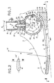
- the articulated foot shown in Figure 1 has a cosmetic Envelope 1 made of suitable material that has an ankle area 2, a toe area 3, a heel area 4 and defines a sole area 5.
- a leaf spring 10 is also provided which approximates extends parallel to the sole area 5 and with its front End 12 extends into the toe area 3.
- the leaf spring 10 can consist of different materials, preferably made of impregnated glass fibers in a matrix of polymer Resin.
- the leaf spring 10 has a preferably asymmetrical Form on and is configuring a left or right Adjusted foot with a longitudinal axis AA 'in the figure 1 sagittal plane shown. Basically, however also a symmetrical design with respect to the axis AA ' the leaf spring 10 possible.
- the bottom 10a of the leaf spring 10 is over most of the length of the leaf spring 10 convex, the curvature resulting from that in FIG drawn curve radius R with constant center 0 or from a combination of such a radius with a displaceable Center point results.
- FIGS. 1 and 2 is the leaf spring 10 with a rear extension 11 provided, from which the strength of the leaf spring 10 to the front end 12 decreases evenly.
- the rear approach 11 forms a stop 13 and merges forward into one Saddle 14 defined by the top 10b of the leaf spring 10 and has a curvature that has a circular section with a center at 0 '.
- the leaf spring 10 has an approximately constant Strength on, the decrease only in front of the saddle 14 in the direction of the front leaf spring end 12 is used.
- the artificial foot also has one Foot insert 20, which rests on the saddle 14 and with this is detachably connected.
- the foot insert 20 consists essentially a cylindrical segment 21 made of a composite material, the robustness, elasticity and low specific weight guaranteed.
- the material can be made in a polymer resin matrix embedded fiberglass layers exist.
- the cylindrical Segment 21 defines a cylinder axis 0 ', largely has one constant wall thickness and is on the back with a provided relatively wide axial slot 22 through which the cylindrical segment 21 seen in cross section approximately the shape receives a C open to the rear, which is made up of an upper, upper C-leg 23 extending over the angular range ⁇ , a lower C-leg, which extends over the angular range ⁇ 24 and one of the two legs 23, 24 with each other connecting, extending over the angular range ⁇ Bridge 25 is composed.
- the cylindrical segment 21 is fixed on the saddle 14 by a screw bolt 26, which is arranged such that its bolt axis 15 intersects the center point of the cylindrical segment 21 defined by the cylinder axis 0 '.
- FIG. 1 also shows that the connection of the cylindrical segment 21 to the saddle 14 of the leaf spring 10 defined by the screw bolt 26 is offset by an angle T with respect to the vertical D running through 0 ', the angle T preferably being between 35 ° and 45 °, but especially at 40 °.
- the artificial plane lying flat on an approximately horizontal support surface PP ' has the common plane of the free end 24' of the lower C-leg 24 of the cylindrical segment 21 and of its cylinder axis 0 'approximately horizontal.
- the upper C-leg 23 is connected to an adapter 30 which, in the embodiment according to FIG. 1, has a tube extension 31 which defines the lower leg or the shin.
- the adapter 30 is supported with a shoulder 32 on the outer circumference of the upper C-leg 23 and can be fixed opposite this by a screw bolt 33, which is supported by a supporting wedge 34 that is supported against the underside of the upper C-leg 23 upper C-leg 23 in its.
- Elongated hole 35 extends circumferentially and is screwed into the bottom surface of a tubular connecting piece 36.
- the latter projects to its centering with a cylindrical projection 37 in a corresponding recess 38 in the top of the adapter projection 32.
- the adapter projection 32 can be moved within the angular range f 1 relative to the upper C-leg 23 and in the desired Fix the position by tightening the screw bolt 33.
- By loosening the screw bolt 33 there is also a certain clearance between the adapter neck 32 and the upper C-leg 23. This enables an azimuth adjustment on the artificial foot itself on the vertical D between the tubular socket 36 and the adapter neck 32.
- this design of the foot adapter 30 permits a pointed or ankle adjustment of the prosthesis and, by means of the azimuth adjustment mentioned, a laterally convex (O position) or a laterally concave (X position) joint adjustment.
- a laterally convex (O position) or a laterally concave (X position) joint adjustment When tightening the screw bolt 33, all essential parts of the foot adapter 30 are also simultaneously fixed in a position above the upper C-leg 23.
- Figure 1 also shows that the free edge 24 'of the lower C-leg 24 is provided with a shock absorber 40 which with should interact with the free edge 23 'of the upper C-leg, when the cylindrical segment 21 has a corresponding load is subjected.
- This bondage 50 can be a fabric belt, for example, and is used primarily in addition, an excessive spreading apart of the two C-legs 23, 24 to prevent.
- the leaf spring 10 on its underside 10a with a toe sole 60 and with a Heel wedge 61 fitted, for example glued. It is the heel wedge 61 is preferably flush with the rear end 13 of the Leaf spring 10 adapted to an effective attachment here achieve and at the same time a support for the rear leaf spring end 13 to form.
- the artificial foot described above is particularly light and allows a natural gait, the resilient Properties in particular due to the rear-mounted attachment of the cylindrical segment 21 on the rear section the leaf spring 10 can be positively influenced.
- the pressure over the heel wedge 61 or over the heel of the cosmetic cover 1 leads to a compression of the cylindrical segment 21, whereby the axial slot 22 partially or completely closes.
- the prosthesis structure is lowered by one Axis that is close to the physiological ankle axis; this In the exemplary embodiment according to FIG. 1, the axis is a cylinder axis 0 'shown. This results in a natural appearance, which allows a smooth gait, which in particular allows movement simplified in descending and a natural rolling is ensured if the foot after putting on the heel fully occurs and rolls.
- Structural details such as length and thickness of the leaf spring 10, material thickness and diameter of the cylindrical segment 21 and The size of his axial slot 22 is known to the person skilled in the art Adjust the prosthesis wearer, especially his weight.
- the elastic deformability of the cylindrical segment 21 through its axial slot 22 enables relative rotation of the upper C-leg 23 opposite the web 25 or the lower one C-leg 24, so that twisting movements of the foot around the leg axis, e.g. when moving forward are possible.
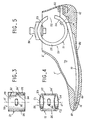
- the cylindrical Segment 21 according to Figure 4 be formed.
- the two End faces C1, C2 of the foot insert 20 in a side view mirror image oblique to the cylinder axis 0 'and converge radially outwards, so that the upper C-leg 23 is narrower is as the lower C-leg mounted on the saddle 14 24th
- the heel wedge 61 of the cosmetic sleeve 1 ' is by only one schematically indicated fastener 82 with the rear End 13 of the leaf spring 10 connected so that the sleeve 1 'opposite the leaf spring 10 has no relative sliding movement along the Saggital plane capable of executing.
Landscapes
- Health & Medical Sciences (AREA)
- Transplantation (AREA)
- Life Sciences & Earth Sciences (AREA)
- Animal Behavior & Ethology (AREA)
- Engineering & Computer Science (AREA)
- Biomedical Technology (AREA)
- Heart & Thoracic Surgery (AREA)
- Vascular Medicine (AREA)
- Cardiology (AREA)
- Oral & Maxillofacial Surgery (AREA)
- General Health & Medical Sciences (AREA)
- Public Health (AREA)
- Veterinary Medicine (AREA)
- Orthopedic Medicine & Surgery (AREA)
- Prostheses (AREA)
- Mechanical Operated Clutches (AREA)
- Massaging Devices (AREA)
Abstract
Description
Erste Lösungsvorschläge sahen für den Kunstfuß eine starre, z.B. aus Holz bestehende Ausführung vor, die später mit einem Gelenk versehen wurde, um die Funktion des Knöchels nachzuahmen. Bei einer Weiterentwicklung wurde dann bereits ein federelastischer, aus Blattfedern zusammengesetzter Fußeinsatz vorgesehen, der mit Schaumstoff umkleidet wurde (siehe z.B. US-A-4,959,073).The first proposed solutions saw a rigid, e.g. wooden existing version, which was later articulated to mimic the function of the ankle. In a further development then already a spring-elastic foot insert composed of leaf springs provided that was lined with foam (see e.g. US-A-4,959,073).
Die DE 40 38 063 C2 offenbart einen gelenklosen Prothesenfuß mit einem einteilig ausgebildeten, zumindest eine Plantar- und Dorsalflexion sowie eine axiale Kompression ermöglichenden Fußeinsatz, der im Fußlängsschnitt eine angenähert S-förmige Ausbildung aufweist. Der obere Schenkel bildet mit einem sich unter einem stumpfen Winkel anschließenden vorderen Schrägschenkel ein insgesamt starres Winkelelement, an dessen unteres Ende sich ein mittlerer, blattfederähnlicher Schenkel anschließt, der an seinem hinteren Ende über eine angenähert halbkreisförmige Schenkelverbindung mit dem unteren Schenkel verbunden ist. Dabei erstreckt sich das untere Ende des starren Winkelelementes nach vorn bis etwa in den Bereich der Zehen-Grundgelenke. DE 40 38 063 C2 discloses an articulated prosthetic foot with one one-piece, at least one plantar and dorsiflexion and one Axial compression allows foot insert, the one in the longitudinal foot section has approximately S-shaped design. The upper leg forms with one front oblique legs adjoining at an obtuse angle an overall rigid angle element, at the lower end of which a middle, leaf spring-like leg connects to the rear End via an approximately semicircular leg connection with the lower one Leg is connected. The lower end of the rigid extends Angle element forward to about the area of the basic toe joints.
Die FR-A1-26 40 499 offenbart einen gelenklosen Kunstfuß mit einem innerhalb eines Fußformteils angeordneten federelastischen Fußeinsatz, der im Längsschnitt angenähert C-förmig mit nach hinten liegender Öffnung ausgebildet ist und die Prothesenbelastung mit seinem oberen C-Schenkel aufnimmt und über seinen unteren C-Schenkel auf eine mit ihm verbundene Blattfeder überträgt, die sich angenähert parallel zum Sohlenbereich nach vorn über den Fußeinsatz hinaus erstreckt und mit ihrem vorderen Ende bis in den Fußspitzenbereich ragt. Der Mittelteil dieses Fußeinsatzes liegt etwa im vorderen Längendrittel der Sohle, während der obere C-Schenkel eine Verbindung mit der Beinprothese bildet. Der C-förmige Fußeinsatz übernimmt eine Federfunktion, die durch ein zwischen die beiden C-Schenkel gelegtes federelastisches Polster ergänzt wird, um eine gewisse Geschmeidigkeit beim Aufsetzen des Fußes zu erreichen. Die sich über angenähert die volle Länge des Kunstfußes erstrekkende Blattfeder ist auf ihrer Unterseite über etwa 2/3 ihrer Länge überwiegend konkav und über ihr vorderes Drittel überwiegend konvex ausgebildet. Jedoch hat sich in der Praxis gezeigt, dass auch dieser Kunstfuß keinen natürlichen Gangablauf ermöglicht.FR-A1-26 40 499 discloses a hinged artificial foot with an inside a resilient foot insert arranged in the Longitudinal section approximately C-shaped with opening to the rear and takes up the prosthesis load with its upper C-leg and over its lower C-leg to a leaf spring connected to it transmits, which is approximately parallel to the sole area forward over the Foot insert extends and with its front end to the toe area protrudes. The middle part of this foot insert lies approximately in the front third of the length the sole, while the upper C-leg connects to the Forms prosthetic leg. The C-shaped foot insert takes on a spring function, the by a resilient cushion placed between the two C-legs is added to a certain suppleness when putting the foot on to reach. Which extends over approximately the full length of the artificial foot Leaf spring is predominant on its underside over about 2/3 of its length concave and predominantly convex over its front third. however has shown in practice that this artificial foot is not a natural one either Gear sequence allows.
Einen weiteren gelenklosen Kunstfuß offenbart das deutsche Gebrauchsmuster G 93 15 665.0 bzw. die EP-A-0 648 479. Hier ist ein Schaumkunststoff-Fußformteil mit einem metallischen Versteifungskörper vorgesehen, der durch ein liegendes, nach hinten offenes U-Profil gebildet wird, dessen jeweilige Schenkel bei Belastung elastisch aufeinander zu bewegbar sind. Die auslaufenden Schenkelabschnitte weisen zu ihrem freien Ende hin eine abnehmende Materialstärke auf, während die Schenkelenden mit Verdickungen versehen sind. Der untere U-Schenkel ist an seinem freien Ende mit einer Blattfeder verschraubt, während der obere U-Schenkel mit der Aufnahme eines Beinanschlußteils verbunden ist. Die Blattfeder kann aus Kohlefaser oder Titan bestehen, wobei die Unterseite der Blattfeder in dem nach vorn über den Fußeinsatz hinaus reichenden Abschnitt überwiegend konvex ausgebildet ist und im Ballenbereich eine nach unten gerichtete Kröpfung aufweist, die dem Abrollprofil des Fußes entsprechend geformt ist. Das vordere Ende der Blattfeder ist in einem Vorfußkern, ihr hinteres Ende in einer im Fersenbereich liegenden Lasche eingebettet. Die mit den Verdickungen versehenen Schenkelenden der C-Schenkel weisen übereinander liegende Bohrungen auf, durch die von unten ein Bolzen durch die beiden Schenkelenden steckbar und mit einer Aufnahme eines Beinanschlussteils verschraubbar ist. Der Zwischenraum zwischen den freien U-Schenkeln kann mit einem weichen Polyurethanschaum ausgefüllt sein. Dieses Sprungfederelement soll eine Fußbewegung im Sinne einer Pro-Subination um die Fußlängsachse sowie einen natürlichen Bewegungsablauf gestatten.The German utility model reveals another articulated foot without hinges G 93 15 665.0 or EP-A-0 648 479. Here is a foam plastic foot molding provided with a metallic stiffening body through a lying, U-profile open to the rear is formed, its respective Legs are elastically movable towards each other under load. The expiring Leg sections have a decreasing towards their free end Material thickness while the thigh ends are provided with thickenings are. The lower U-leg is screwed to a leaf spring at its free end, while the upper U-leg with the inclusion of a leg connector connected is. The leaf spring can be made of carbon fiber or titanium, with the bottom of the leaf spring in the forward over the foot insert extending portion is predominantly convex and in the ball area has a downward bend that the rolling profile of the foot is shaped accordingly. The front end of the leaf spring is in a forefoot core, its rear end in a flap in the heel area embedded. The thickened leg ends of the C-legs have bores lying one above the other through which from below a bolt can be inserted through the two leg ends and with one receptacle a leg connector is screwed. The space between the free U-legs can be filled with a soft polyurethane foam his. This spring element is supposed to be a foot movement in the sense of a pro-subination around the longitudinal axis of the foot as well as a natural movement allow.
Der Erfindung liegt die Aufgabe zugrunde, einen gelenklosen Kunstfuß, wie er sich beispielsweise der EP-A-0 648 479 entnehmen lässt, hinsichtlich der Dämpfung des Auftritts der Ferse, der Durchfederung, des Abrollens und der Seitenstabilität zu verbessern, um so dem Träger einen natürlichen Gang zu ermöglichen, wobei der Träger in die Lage versetzt werden soll, sowohl normal zu gehen, als auch körperliche Übungen und Sport zu betreiben.The invention has for its object a hinged artificial foot as he can be found, for example, in EP-A-0 648 479 with regard to the Dampening of the appearance of the heel, the deflection, the rolling and the Improve lateral stability so that the wearer can walk naturally allow, where the carrier should be able to, both normal to go as well as do physical exercises and sports.
Diese Aufgabe wird gemäß der Erfindung durch einen gelenklosen Kunstfuß mit den Merkmalen des Anspruchs 1 gelöst.This object is achieved according to the invention by an articulated foot solved with the features of claim 1.
Dabei ist es zweckmäßig, wenn der Sattel der Blattfeder zu deren hinterem Ende hin kreissegmentförmig hochgezogen ist, wobei der Fußeinsatz auf diesem Sattel vorzugsweise lösbar befestigt ist. Diese Befestigung kann über einen Schraubbolzen oder eine Klemmverbindung erfolgen. Wesentlich ist dabei, dass diese Verbindung mit lichtem Abstand hinter der durch die Zylinderachse geführten Vertikalen liegt. Vor der Befestigungsstelle wird dadurch ein sich keilförmig auf die Befestigungsstelle hin verjüngender Abstand zwischen dem vorderen Abschnitt des unteren C-Schenkels und der darunterliegenden Blattfeder geschaffen. Der so geschaffene Einfederbereich trägt wesentlich zur Erzielung eines natürlichen Bewegungsablaufs bei.It is useful if the saddle of the leaf spring to the rear End is drawn up in a segment of a circle, with the foot insert on this Saddle is preferably releasably attached. This attachment can be made using a Screw bolts or a clamp connection. It is essential that this connection is a short distance behind that through the cylinder axis guided verticals. In front of the attachment point, this becomes a wedge-shaped distance between the front section of the lower C-leg and the leaf spring underneath. The so created Compression area contributes significantly to achieving a natural Movement sequence at.
Weitere Merkmale der Erfindung sind Gegenstand der Unteransprüche und werden in Verbindung mit weiteren Vorteilen der Erfindung anhand von Ausführungsbeispielen näher erläutert.
- Figur 1
- zeigt einen gelenklosen Kunstfuß im Längsschnitt in der Saggitalebene der Prothese;
-
Figur 2 - zeigt stark verkleinert und in schematischer Darstellung einen Schnitt gemäß der Linie II-II in Figur 1;
- Figur 3
- zeigt in verkleinertem Maßstab den in Figur 1 dargestellten Fußeinsatz in Draufsicht;
- Figur 4
- zeigt für den Fußeinsatz eine abgewandelte Ausführungsform in einer Darstellung gemäß Figur 3 und
-
Figur 5 - zeigt für einen gelenklosen Kunstfuß eine Ausführungsvariante in einer Darstellung gemäß Figur 1.
- Figure 1
- shows a jointless artificial foot in longitudinal section in the sagittal plane of the prosthesis;
- Figure 2
- shows greatly reduced and a schematic representation of a section along the line II-II in Figure 1;
- Figure 3
- shows on a smaller scale the foot insert shown in Figure 1 in plan view;
- Figure 4
- shows for the foot insert a modified embodiment in a representation according to Figure 3 and
- Figure 5
- shows an embodiment variant for a jointless artificial foot in a representation according to FIG. 1.
Der in Figur 1 dargestellte gelenklose Kunstfuß weist eine kosmetische
Hülle 1 aus geeignetem Material auf, die einen Knöchelbereich
2, einen Fußspitzenbereich 3, einen Fersenbereich 4 und
einen Sohlenbereich 5 definiert.The articulated foot shown in Figure 1 has a cosmetic
Envelope 1 made of suitable material that has an
Vorgesehen ist ferner eine Blattfeder 10, die sich angenähert
parallel zum Sohlenbereich 5 erstreckt und mit ihrem vorderen
Ende 12 bis in den Fußspitzenbereich 3 ragt. Die Blattfeder 10
kann aus unterschiedlichen Materialien bestehen, vorzugsweise
aus imprägnierten Glasfasern in einer Matrix aus polymerem
Kunstharz. Die Blattfeder 10 weist eine vorzugsweise asymmetrische
Form auf und ist der Konfiguration eines linken oder rechten
Fußes mit einer Längsachse AA' angepaßt, die in der in Figur
1 dargestellten Sagittalebene liegt. Grundsätzlich ist allerdings
auch eine bezogen auf die Achse AA' symmetrische Ausbildung
der Blattfeder 10 möglich. Die Unterseite 10a der Blattfeder
10 ist über den größten Teil der Länge der Blattfeder 10
konvex ausgebildet, wobei sich die Krümmung aus dem in Figur 1
eingezeichneten Kurvenradius R mit konstantem Mittelpunkt 0 oder
aus einer Kombination eines derartigen Radius mit verschiebbarem
Mittelpunkt ergibt.A
In den beiden in den Figuren 1 und 2 dargestellten Ausführungsbeispielen
ist die Blattfeder 10 mit einem hinteren Ansatz 11
versehen, ausgehend von dem die Stärke der Blattfeder 10 zu deren
vorderen Ende 12 hin gleichmäßig abnimmt. Der hintere Ansatz
11 bildet einen Anschlag 13 und geht nach vorn über in einen
Sattel 14, der durch die Oberseite 10b der Blattfeder 10 definiert
ist und eine Krümmung aufweist, die einen Kreisabschnitt
mit einem Mittelpunkt bei 0' darstellen kann. Im Bereich dieses
Sattels 14 weist die Blattfeder 10 eine angenähert konstante
Stärke auf, deren Abnahme erst vor dem Sattel 14 in Richtung auf
das vordere Blattfederende 12 einsetzt.In the two exemplary embodiments shown in FIGS. 1 and 2
is the
Zusätzlich zu der Blattfeder 10 weist der Kunstfuß noch einen
Fußeinsatz 20 auf, der auf dem Sattel 14 aufliegt und mit diesem
lösbar verbunden ist. Der Fußeinsatz 20 besteht im wesentlichen
aus einem zylindrischen Segment 21 aus einem Verbundwerkstoff,
der Robustheit, Elastizität und geringes spezifisches Gewicht
gewährleistet. Der Werkstoff kann aus in einer polymeren Kunstharzmatrix
eingebetteten Glasfaserlagen bestehen. Das zylindrische
Segment 21 definiert eine Zylinderachse 0', hat eine weitgehend
konstante Wandungsstärke und ist rückseitig mit einem
verhältnismäßig breiten Axialschlitz 22 versehen, durch den das
zylindrische Segment 21 im Querschnitt gesehen etwa die Form
eines nach hinten offenen C erhält, das sich aus einem oberen,
über den Winkelbereich α erstreckenden oberen C-Schenkel 23,
einem unteren, sich über den Winkelbereich β erstreckenden C-Schenkel
24 sowie aus einem die beiden Schenkel 23, 24 miteinander
verbindenden, sich über den Winkelbereich γ erstreckenden
Steg 25 zusammensetzt.In addition to the
Gemäß Ausführungsbeispiel erfolgt die Festlegung des zylindrischen
Segmentes 21 auf dem Sattel 14 durch einen Schraubbolzen
26, der so angeordnet ist, daß seine Bolzenachse 15 den durch
die Zylinderachse 0' definierten Mittelpunkt des zylindrischen
Segmentes 21 schneidet. Figur 1 läßt ferner erkennen, daß die
durch den Schraubbolzen 26 definierte Verbindung des zylindrischen
Segmentes 21 mit dem Sattel 14 der Blattfeder 10 gegenüber
der durch 0' verlaufenden Vertikalen D um einen Winkel T nach
hinten versetzt angeordnet ist, wobei der Winkel T vorzugsweise
zwischen 35° und 45°, insbesondere aber bei 40° liegt. Hierdurch
wird deutlich, daß die Verbindungsstelle zwischen dem zylindrischen
Segment 21 und der Blattfeder 10 gegenüber der Vertikalen
D deutlich nach hinten verlagert ist, wodurch sich diese erfindungsgemäße
Lösung wesentlich von allen vorbekannten Ausführungsformen
unterscheidet. Dabei kann es zweckmäßig sein, wenn
bei flach auf einer angenähert horizontalen Auflagefläche PP'
aufliegendem Kunstfuß die gemeinsame Ebene von dem freien Ende
24' des unteren C-Schenkels 24 des zylindrischen Segmentes 21
sowie von dessen Zylinderachse 0' angenähert horizontal liegt.
Der obere C-Schenkel 23 ist mit einem Adapter 30 verbunden, der
bei der Ausführungsform gemäß Figur 1 eine Rohrverlängerung 31
aufweist, die den Unterschenkel bzw. das Schienbein definiert.
Der Adapter 30 stützt sich mit einem Ansatz 32 auf dem äußeren
Umfang des oberen C-Schenkels 23 ab und ist diesem gegenüber
durch einen Schraubbolzen 33 festlegbar, der durch einen sich
gegen die Unterseite des oberen C-Schenkels 23 abstützenden
Stützkeil 34, ein sich im oberen C-Schenkel 23 in dessen. Umfangsrichtung
erstreckendes Langloch 35 geführt und in die Bodenfläche
eines rohrförmigen Stutzens 36 geschraubt ist. Letzterer
ragt zu seiner Zentrierung mit einem zylindrischen Ansatz 37
in eine entsprechende Ausnehmung 38 in der Oberseite des Adapteransatzes
32. Nach dem Lösen des Schraubbolzens 33 läßt sich
der Adapteransatz 32 innerhalb des Winkelbereichs f1 gegenüber
dem oberen C-Schenkel 23 verschieben und in der gewünschten Position
durch Anziehen des Schraubbolzens 33 fixieren. Durch Lösen
des Schraubbolzens 33 ergibt sich überdies ein gewisser
Spielraum zwischen dem Adapteransatz 32 und dem oberen C-Schenkel
23. Hierdurch wird eine Azimut-Einstellung am Kunstfuß
selbst auf der Vertikalen D zwischen dem rohrförmigen Stutzen 36
und dem Adapteransatz 32 ermöglicht. Insgesamt erlaubt diese
Ausbildung des Fußadapters 30 eine Spitzfuß- oder Sprungbein-Justierung
der Prothese sowie durch die genannte Azimut-Verstellung
eine lateral konvexe (O-Stellung) bzw. eine lateral konkave
(X-Stellung) Gelenkverstellung. Beim Anziehen des Schraubbolzens
33 werden außerdem gleichzeitig alle wesentlichen Teile des Fußadapters
30 in einer Position oberhalb des oberen C-Schenkels 23
fixiert.According to the exemplary embodiment, the
Figur 1 läßt ferner erkennen, daß der freie Rand 24' des unteren
C-Schenkels 24 mit einem Stoßdämpfer 40 versehen ist, der mit
dem freien Rand 23' des oberen C-Schenkels zusammenwirken soll,
wenn das zylindrische Segment 21 einer entsprechenden Belastung
unterworfen wird.Figure 1 also shows that the free edge 24 'of the lower
C-
Bei dem Ausführungsbeispiel gemäß Figur 1 ist der Axialschlitz
22 des zylindrischen Segmentes 21 durch eine Fessel 50 überbrückt,
die die beiden C-Schenkel 23, 24 auf der dem Steg 25
gegenüberliegenden Seite miteinander verbindet. Diese Fessel 50
kann beispielsweise ein Stoffgurt sein und dient in erster Linie
dazu, ein übermäßiges Auseinanderspreizen der beiden C-Schenkel
23, 24 zu verhindern.In the embodiment shown in Figure 1 is the
Bei dem Ausführungsbeispiel gemäß Figur 1 ist die Blattfeder 10
auf ihrer Unterseite 10a mit einer Fußspitzsohle 60 und mit einem
Fersenkeil 61 bestückt, beispielsweise verklebt. Dabei ist
der Fersenkeil 61 vorzugsweise bündig an das hintere Ende 13 der
Blattfeder 10 angepaßt, um hier eine wirksame Befestigung zu
erzielen und zugleich eine Abstützung für das hintere Blattfederende
13 zu bilden.In the exemplary embodiment according to FIG. 1, the
Der vorstehend beschriebene Kunstfuß baut besonders leicht und
ermöglicht einen natürlichen Gang, wobei die federelastischen
Eigenschaften insbesondere durch die nach hinten verlegte Befestigung
des zylindrischen Segmentes 21 auf dem hinteren Abschnitt
der Blattfeder 10 positiv beeinflußt werden. Der Druck
über den Fersenkeil 61 oder über die Ferse der kosmetischen Hülle
1 führt zu einem Zusammendrücken des zylindrischen Segmentes
21, wodurch sich der Axialschlitz 22 teilweise oder völlig
schließt. Es folgt eine Absenkung der Prothesenstruktur um eine
Achse, die nahe der physiologischen Knöchelachse liegt; diese
Achse ist im Ausführungsbeispiel gemäß Figur 1 als Zylinderachse
0' dargestellt. Hierdurch ergibt sich ein natürliches Auftreten,
das einen weichen Gang ermöglicht, wodurch insbesondere die Bewegung
im Heruntergehen vereinfacht und ein natürliches Abrollen
gewährleistet wird, wenn der Fuß nach dem Aufsetzen der Ferse
vollständig auftritt und abrollt. Diese aufeinanderfolgenden
Phasen werden durch die Wirkung der Blattfeder 10 harmonisiert,
deren große Länge sowie leichte Krümmung in der Abrollrichtung
eine elastische Verformung begünstigen und diese von der Fußsohle
auf die Auflagefläche verlagern, um so die Gewichtsverlagerung
der gehenden Person abzufedern. Sobald die Streckphase
beendet ist, beginnt die Abrollphase auf Höhe der Blattfeder 10,
die fortschreitend vom Zusammendruck entlastet wird. Diese Entlastung
führt zu einer Abgabe der durch das zylindrische Segment
21 gespeicherten Energie und dann zu einer Kombination mit den
Reaktionen der Blattfeder, um dann mit einer einzigen elastischen
Reaktion der Blattfeder abzuschließen, sowie die Fessel 50
gespannt ist. Die Kombination aufeinanderfolgender elastischer
Reaktionen bewirkt einen geschmeidigen und leichten Gang, der
dem natürlichen Gang sehr nahe kommt.The artificial foot described above is particularly light and
allows a natural gait, the resilient
Properties in particular due to the rear-mounted attachment
of the
Konstruktive Details wie Länge und Dicke der Blattfeder 10, Materialstärke
und Durchmesser des zylindrischen Segmentes 21 sowie
Größe seines Axialschlitzes 22 wird der Fachmann dem jeweiligen
Prothesenträger, insbesondere seinem Gewicht anpassen.Structural details such as length and thickness of the
Die elastische Verformbarkeit des zylindrischen Segmentes 21
durch dessen Axialschlitz 22 ermöglicht eine relative Verdrehung
des oberen C-Schenkels 23 gegenüber dem Steg 25 bzw. dem unteren
C-Schenkel 24, so daß Verdrehbewegungen des Fußes um die Beinachse,
z.B. bei der Vorwärtsbewegung, möglich sind.The elastic deformability of the
Zur Unterstützung derartiger Bewegungen kann das zylindrische
Segment 21 gemäß Figur 4 ausgebildet sein. Hier liegen die beiden
Stirnseiten C1, C2 des Fußeinsatzes 20 in Seitenansicht
spiegelbildlich schräg zur Zylinderachse 0' und konvergieren
radial nach außen, so daß der obere C-Schenkel 23 schmaler ausgebildet
ist als der auf dem Sattel 14 montierte untere C-Schenkel
24.To support such movements, the
Bei einer abgewandelten Ausführungsform gemäß Figur 5 werden die
Fußspitzsohle 60 und der Fersenkeil 61 unmittelbar von einer
Hülle 1' gebildet, die einen Hohlraum 70 umschließt, der sowohl
die Blattfeder 10 als auch das zylindrische Segment 21 aufnimmt.
Letzteres weist gegenüber der Hülle 1' einen lichten Abstand
auf, der bei Verformungen des zylindrischen Segmentes 21 und/oder
Verdrehungen seines oberen C-Schenkels 23 jede Berührung
bzw. Reibung an dem Knöchelbereich 2' unterbindet. Bei dieser
Ausführungsform bildet die Hülle 1' auch eine Sohle 80, die die
Fußspitzsohle 60 mit dem Fersenkeil 61 verbindet. Figur 5 läßt
ferner erkennen, daß das vordere Ende 12 der Blattfeder 10 so in
einen vorderen Gleitabschnitt 81 des von der kosmetischen Hülle
1' umschlossenen Hohlraumes 70 ragt, daß zwischen dem Blattfederende
12 und der kosmetischen Hülle 1' noch ein Gleitbereich
verbleibt.In a modified embodiment according to FIG
Sole of
Der Fersenkeil 61 der kosmetischen Hülle 1' ist durch ein nur
schematisch angedeutetes Befestigungsmittel 82 mit dem hinteren
Ende 13 der Blattfeder 10 so verbunden, daß die Hülle 1' gegenüber
der Blattfeder 10 keine relative Gleitbewegung entlang der
Saggitalebene auszuführen vermag.The
Die Erfindung ist nicht auf die in den Figuren dargestellten und vorstehend beschriebenen Ausführungsbeispiele beschränkt; diverse Modifikationen sind möglich, ohne den Bereich der Erfindung zu verlassen.The invention is not limited to that shown in the figures and limited embodiments described above; various Modifications are possible without the scope of the invention to leave.
Claims (24)
- Jointless artificial foot for a leg prosthesis, with the following features:a) a resilient foot insert (20) is arranged within a foot moulding (1, 2, 3, 4) and is approximately C-shaped in longitudinal section with an opening (22) situated towards the rear and accommodates the load of the prosthesis with its upper C-arm (23) and transmits said load via its lower C-arm (24) to a leaf spring (10) connected to it;b) the foot insert (20) is formed substantially by a horizontally arranged tubular cylindrical segment (21) which has a horizontal cylinder axis (0') and an axial slot for the purpose of forming the aforementioned rear opening (22);c) the leaf spring (10) extends forwards beyond the foot insert (20) approximately parallel to the sole region (5) and projects into the foot-point region (3) with its front end (12);d) the underside (10a) of the leaf spring (10) is of predominantly convex construction in the region between the foot insert (20) and the free end (12) of the leaf spring;e) the upper side (10b) of the leaf spring (10) forms in the rear end region thereof a saddle (14) for supportive accommodation and fixation of a section of the lower C-arm (24) of the foot insert (20);f) the upper C-arm (23) is provided with a foot adapter (30) for detachable connection to a leg prosthesis.
- Artificial foot according to Claim 1, characterised in that the saddle (14) of the leaf spring (10) is raised in the form of a circular segment in the direction towards the rear end (13) of said leaf spring.
- Artificial foot according to Claim 1 or 2, characterised in that the foot insert (20) is detachably fastened to the saddle (14) of the leaf spring (10).
- Artificial foot according to Claim 3, characterised in that the lower C-arm (24) of the cylindrical segment (21) is fastened to the saddle (14) of the leaf spring (10) via a screw bolt (26) or a clamp connection which is situated with a spacing () behind the vertical (D) passing through the cylinder axis (O').
- Artificial foot according to Claim 4, characterised by the use of a screw bolt (26), the axis (15) of which includes an angle () of about 40° with the vertical (D) passing through the cylinder axis (O').
- Artificial foot according to one of the preceding claims, characterised in that in the case of an artificial foot lying flat on an approximately horizontal bearing surface (pp') the common plane pertaining to the free end (24') of the lower C-arm (24) of the foot insert (20) and also pertaining to the cylinder axis (0') thereof is approximately horizontal.
- Artificial foot according to one of the preceding claims, characterised in that the foot insert (20) has a constant wall thickness.
- Artificial foot according to one of the preceding claims, characterised in that the leaf spring (10) comprises sections of differing thickness and/or width.
- Artificial foot according to one of the preceding claims, characterised in that in side view the two end faces (C1, C2) of the foot insert (20) are in mirror-image oblique arrangement in relation to the cylinder axis (O') and converge radially outwards so that the upper C-arm (23) is narrower than the lower C-arm (24) mounted on the saddle (14).
- Artificial foot according to Claims 1 to 8, characterised in that the two end faces (C1, C2) of the foot insert (20) are in parallel oblique arrangement in relation to the cylinder axis (O').
- Artificial foot according to one of the preceding claims, characterised in that the upper C-arm (23) is of narrower construction in the region in front of the foot adapter (30).
- Artificial foot according to one of the preceding claims, characterised by a fetter (50) spanning the axial slot (22) of the cylindrical segment (21) and connecting the two C-arms (23, 24) to one another.
- Artificial foot according to one of the preceding claims, characterised in that a damper (40) is arranged in the region of the axial slot (22).
- Artificial foot according to one of the preceding claims, characterised in that the foot adapter (30) is adjustable relative to the upper C-arm (23) of the foot insert (20) in the peripheral direction (f1) thereof and is capable of being fixed in the desired position on the upper C-arm (23).
- Artificial foot according to one of the preceding claims, characterised in that the foot adapter (30) is adjustable in the radial direction in relation to the foot insert (20).
- Artificial foot according to one of the preceding claims, characterised in that the foot adapter (30) is rotatable in relation to the foot insert (20) about the vertical axis (D) and is capable of being fixed in the desired position.
- Artificial foot according to one of the preceding claims, characterised in that the optionally multicomponent foot adapter (30) is fastened to the foot insert (20) via a screw bolt (33) which is radially aligned in relation to the cylindrical segment (21) and - with respect to the length of the foot - is situated in front of the fastening (26) of the foot insert (20) to the leaf spring (10) subject to a spacing.
- Artificial foot according to Claim 17, characterised in that the screw bolt (33) is passed through an elongate hole (35) in the upper C-arm (23) extending in the peripheral direction.
- Artificial foot according to one of the preceding claims, characterised in that the leaf spring (10) is provided on its underside (10a) with a heel wedge (61).
- Artificial foot according to Claim 19, characterised in that the heel wedge (61) is fastened to a rear extension (11) of the leaf spring (10).
- Artificial foot according to one of the preceding claims, characterised in that the leaf spring (10) is provided on its underside (10a) with a foot-point sole (60).
- Artificial foot according to Claims 19 and 21, characterised in that foot-point sole (60) and heel wedge (61) are constructed in one piece with a sole (80) connecting these two sections to one another.
- Artificial foot according to one of the preceding claims, characterised by a cosmetic covering (1; 1') extending into the ankle region (2; 2'), said cosmetic covering surrounding the leaf spring (10) completely and surrounding the foot insert (20) at least to a large extent.
- Artificial foot according to Claim 23, characterised in that the front end (12) of the leaf spring (10) projects in such a manner into a front sliding section (81) of the hollow space (70) surrounded by the cosmetic covering (1') that a sliding region still remains between the end (12) of the leaf spring and the cosmetic covering (1').
Applications Claiming Priority (2)
| Application Number | Priority Date | Filing Date | Title |
|---|---|---|---|
| FR9602990A FR2745488B1 (en) | 1996-03-04 | 1996-03-04 | REACTIVE FOOT PROSTHESIS |
| FR9602990 | 1996-03-04 |
Publications (2)
| Publication Number | Publication Date |
|---|---|
| EP0793949A1 EP0793949A1 (en) | 1997-09-10 |
| EP0793949B1 true EP0793949B1 (en) | 2002-06-05 |
Family
ID=9490025
Family Applications (1)
| Application Number | Title | Priority Date | Filing Date |
|---|---|---|---|
| EP96118745A Expired - Lifetime EP0793949B1 (en) | 1996-03-04 | 1996-11-22 | Jointless artificial foot |
Country Status (12)
| Country | Link |
|---|---|
| US (1) | US5897594A (en) |
| EP (1) | EP0793949B1 (en) |
| JP (1) | JP3665172B2 (en) |
| CN (1) | CN1169498C (en) |
| AT (1) | ATE218310T1 (en) |
| CA (1) | CA2198414C (en) |
| DE (1) | DE59609301D1 (en) |
| ES (1) | ES2177710T3 (en) |
| FR (1) | FR2745488B1 (en) |
| RU (1) | RU2168962C2 (en) |
| TW (1) | TW316233B (en) |
| UA (1) | UA44902C2 (en) |
Cited By (1)
| Publication number | Priority date | Publication date | Assignee | Title |
|---|---|---|---|---|
| US8236062B2 (en) | 2001-03-30 | 2012-08-07 | Bioquest Prosthetics Llc | Prosthetic foot with tunable performance |
Families Citing this family (63)
| Publication number | Priority date | Publication date | Assignee | Title |
|---|---|---|---|---|
| US20020087216A1 (en) * | 1996-02-16 | 2002-07-04 | Atkinson Stewart L. | Prosthetic walking system |
| DE19717298C1 (en) * | 1997-04-24 | 1998-05-07 | Bock Orthopaed Ind | Spring-elastic foot prosthesis insert |
| DE29707416U1 (en) * | 1997-04-24 | 1998-08-27 | Otto Bock Orthopädische Industrie Besitz- und Verwaltungs-Kommanditgesellschaft, 37115 Duderstadt | Spring-elastic foot insert |
| JP4212174B2 (en) * | 1998-04-11 | 2009-01-21 | オットー・ボック・ヘルスケア・ゲーエムベーハー | Foot bush for artificial foot |
| FR2782262B1 (en) | 1998-08-17 | 2001-02-09 | Michel Porte | TEST OR IMPLANTABLE COTYLE WITH ADJUSTABLE ORIENTATION |
| US20040056006A1 (en) * | 1998-10-01 | 2004-03-25 | The Welding Institute | Welding method |
| KR100362736B1 (en) * | 2000-04-03 | 2002-12-28 | 한국과학기술원 | Energy-storing prosthetic feet |
| GB2361645A (en) * | 2000-04-26 | 2001-10-31 | Blatchford & Sons Ltd | Prosthetic foot |
| US6562075B2 (en) * | 2001-03-30 | 2003-05-13 | Barry W. Townsend | Prosthetic foot with tunable performance |
| US7108723B2 (en) * | 2000-12-22 | 2006-09-19 | Townsend Barry W | Prosthetic foot |
| US6443995B1 (en) | 2000-12-22 | 2002-09-03 | Barry W. Townsend | Prosthetic foot |
| US7410503B2 (en) * | 2001-03-30 | 2008-08-12 | Bioquest Prosthetics Llc | Prosthetic foot with tunable performance |
| US7611543B2 (en) * | 2001-03-30 | 2009-11-03 | Bioquest Prosthetics, Llc | Prosthetic foot with tunable performance |
| RU2286749C2 (en) * | 2000-12-22 | 2006-11-10 | Барри В. ТАУНСЕНД | Foot's prosthetic appliance |
| WO2002051341A1 (en) * | 2000-12-27 | 2002-07-04 | S.P. Korolev Rocket And Space Public Corporation Energia | Artificial foot |
| US8070829B2 (en) | 2003-09-30 | 2011-12-06 | Bioquest Prosthetics Llc | Prosthetic foot with tunable performance |
| US7374578B2 (en) * | 2001-03-30 | 2008-05-20 | Bioquest Prosthetics, Llc | Prosthetic foot with tunable performance |
| US7954502B2 (en) * | 2001-03-30 | 2011-06-07 | Bioquest Prosthetics, Llc | Mobility assistance apparatus |
| US7429272B2 (en) * | 2001-03-30 | 2008-09-30 | Bioquest Prosthetics Llc | Prosthetic foot with tunable performance |
| US7507259B2 (en) * | 2001-03-30 | 2009-03-24 | Bioquest Prosthetics, Llc | Prosthetic foot with tunable performance |
| US20060185703A1 (en) * | 2001-03-30 | 2006-08-24 | Townsend Barry W | Mobility assistance apparatus |
| US20070213841A1 (en) * | 2001-03-30 | 2007-09-13 | Townsend Barry W | Prosthetic foot with tunable performance |
| US7578852B2 (en) * | 2001-03-30 | 2009-08-25 | Bioquest Prosthetics, Llc | Prosthetic foot with tunable performance and improved vertical load/shock absorption |
| US8007544B2 (en) | 2003-08-15 | 2011-08-30 | Ossur Hf | Low profile prosthetic foot |
| US8574314B2 (en) | 2003-09-30 | 2013-11-05 | Bioquest Prosthetics Llc | Resilient prosthetic and orthotic components which incorporate a plurality of sagittally oriented struts |
| US7520904B2 (en) | 2003-10-21 | 2009-04-21 | Freedom Innovations, Llc | Prosthetic foot with an adjustable ankle and method |
| US20050137717A1 (en) * | 2003-12-18 | 2005-06-23 | Finn Gramnas | Prosthetic foot with rocker member |
| CA2561323C (en) | 2004-04-01 | 2009-09-15 | Barry W. Townsend | Prosthetic foot with tunable performance |
| US8128709B2 (en) * | 2004-05-28 | 2012-03-06 | össur hf | Functional foot cover |
| US7347877B2 (en) * | 2004-05-28 | 2008-03-25 | össur hf | Foot prosthesis with resilient multi-axial ankle |
| US7581454B2 (en) * | 2004-05-28 | 2009-09-01 | össur hf | Method of measuring the performance of a prosthetic foot |
| EP1845906A1 (en) * | 2005-01-25 | 2007-10-24 | College Park Industries, Inc. | Sub-malleolar non-articulating prosthetic foot with improved dorsiflexion |
| US20060241782A1 (en) * | 2005-04-21 | 2006-10-26 | Curtis Michael J | Vertical shock absorbing prosthetic foot |
| US7618463B2 (en) * | 2005-07-11 | 2009-11-17 | össur hf | Energy returning prosthetic joint |
| US20090018669A1 (en) * | 2007-05-18 | 2009-01-15 | Agan Ashley D | Articulating Prosthetic Ankle Joint |
| US10405998B2 (en) | 2007-09-19 | 2019-09-10 | Ability Dynamics Llc | Mounting bracket for connecting a prosthetic limb to a prosthetic foot |
| US10842653B2 (en) | 2007-09-19 | 2020-11-24 | Ability Dynamics, Llc | Vacuum system for a prosthetic foot |
| US12011373B2 (en) | 2007-09-19 | 2024-06-18 | Proteor USA, LLC | Mounting bracket for connecting a prosthetic limb to a prosthetic foot |
| US11020248B2 (en) | 2007-09-19 | 2021-06-01 | Proteor USA, LLC | Vacuum system for a prosthetic foot |
| US7763082B1 (en) | 2007-10-19 | 2010-07-27 | American Prosthetic Components, Inc. | Prosthetic foot with heel and keel springs |
| US7766974B2 (en) * | 2007-10-19 | 2010-08-03 | American Prosthetic Components, Inc. | Prosthetic foot with a processor to manage energy return of adjustable heel and keel springs |
| US8685109B2 (en) * | 2008-07-01 | 2014-04-01 | össur hf | Smooth rollover insole for prosthetic foot |
| RU2482819C2 (en) * | 2009-05-20 | 2013-05-27 | Федеральное государственное учреждение "Санкт-Петербургский научно-практический центр медико-социальной экспертизы, протезирования и реабилитации инвалидов им. Г.А. Альбрехта Федерального агентства по здравоохранению и социальному развитию" (ФГУ "СПбНЦЭР им. Альбрехта Росздрава") | Shin prosthesis |
| WO2011106564A1 (en) * | 2010-02-26 | 2011-09-01 | össur hf | Prosthetic foot with a curved split |
| US9060884B2 (en) | 2011-05-03 | 2015-06-23 | Victhom Human Bionics Inc. | Impedance simulating motion controller for orthotic and prosthetic applications |
| EP2760379B1 (en) | 2011-09-26 | 2017-10-25 | Össur HF | Frictionless vertical suspension mechanism for prosthetic feet |
| US8961618B2 (en) | 2011-12-29 | 2015-02-24 | össur hf | Prosthetic foot with resilient heel |
| EP2879623B1 (en) * | 2012-08-01 | 2019-11-27 | Ossur Hf | Prosthetic ankle module |
| US20150073567A1 (en) * | 2013-09-11 | 2015-03-12 | Michael Thomas Wilson | Composite pylon for a prosthetic device |
| DE102014006687A1 (en) * | 2014-05-09 | 2015-11-12 | Otto Bock Healthcare Gmbh | prosthetic |
| DE102014006744B3 (en) * | 2014-05-12 | 2015-10-08 | Otto Bock Healthcare Gmbh | Artless prosthetic foot |
| US9999524B2 (en) | 2014-06-30 | 2018-06-19 | össur hf | Prosthetic feet and foot covers |
| US20160175118A1 (en) * | 2014-12-18 | 2016-06-23 | Fountainhead, Llc | Prosthetic spacer devices, systems, and methods |
| CA2965997A1 (en) | 2015-01-15 | 2016-07-21 | Ability Dynamics, Llc | Prosthetic foot |
| USD795433S1 (en) | 2015-06-30 | 2017-08-22 | Össur Iceland Ehf | Prosthetic foot cover |
| US9974368B1 (en) * | 2016-02-11 | 2018-05-22 | John Moore | Cane |
| EP3290006B1 (en) * | 2016-08-30 | 2024-01-24 | Fillauer Europe AB | Prosthetic device |
| EP3954341B1 (en) | 2016-12-01 | 2023-08-23 | Össur Iceland EHF | Prosthetic feet having heel height adjustability |
| US11446164B1 (en) | 2017-09-15 | 2022-09-20 | Össur Iceland Ehf | Variable stiffness mechanisms |
| US10980648B1 (en) | 2017-09-15 | 2021-04-20 | Össur Iceland Ehf | Variable stiffness mechanism and limb support device incorporating the same |
| WO2019140255A2 (en) * | 2018-01-11 | 2019-07-18 | Applied Mobility Devices, LLC | Dynamic foot support for walking aid devices |
| USD915596S1 (en) | 2018-04-10 | 2021-04-06 | Össur Iceland Ehf | Prosthetic foot with tapered fasteners |
| CN109199653B (en) * | 2018-10-09 | 2020-07-21 | 广东兰湾智能科技有限公司 | Artificial limb foot |
Family Cites Families (24)
| Publication number | Priority date | Publication date | Assignee | Title |
|---|---|---|---|---|
| FR583917A (en) * | 1924-07-22 | 1925-01-27 | Universal adjustable articulated foot | |
| FR807214A (en) * | 1935-06-06 | 1937-01-07 | Humboldt Deutzmotoren Ag | Motor locomotive powered by gasifier |
| US2453969A (en) * | 1947-04-03 | 1948-11-16 | Edwin C Carter | Artificial limb |
| DE807214C (en) * | 1949-05-23 | 1951-06-25 | Hans Langenohl | Prosthetic foot |
| US3335428A (en) * | 1964-11-02 | 1967-08-15 | Goodrich Co B F | Resilient prosthetic foot made from elastic polymers of different hardness |
| US4547913A (en) * | 1983-07-11 | 1985-10-22 | Flex Foot, Inc. | Composite prosthetic foot and leg |
| DE3741487A1 (en) * | 1987-12-08 | 1989-06-22 | Roland Man Druckmasch | Supporting element which can be inserted between two bones |
| FR2626463B1 (en) * | 1988-01-28 | 1992-06-19 | Espace Composites Sarl | REINFORCEMENT DEVICE FOR PROSTHETIC FOOT |
| US4959073A (en) * | 1988-06-06 | 1990-09-25 | John Merlette | Foot prosthesis and method of making same |
| FR2640499A1 (en) * | 1988-12-15 | 1990-06-22 | Palfray Michel | Novel prosthetic foot structure |
| US5037444A (en) * | 1989-01-05 | 1991-08-06 | Phillips L Van | Prosthetic foot |
| DE3918810A1 (en) * | 1989-06-09 | 1990-12-13 | Bock Orthopaed Ind | JOINTLESS PROSTHESIC FOOT |
| US5139525A (en) * | 1989-07-31 | 1992-08-18 | Kristinsson Oessur | Prosthetic foot |
| GB2241440B (en) * | 1990-02-28 | 1994-06-01 | Blatchford & Sons Ltd | A lower limb prosthesis and an artificial foot for a lower limb prosthesis |
| US5549714A (en) * | 1990-09-21 | 1996-08-27 | Phillips; Van L. | Symes foot prosthesis |
| DE4037928A1 (en) * | 1990-11-24 | 1992-05-27 | Hms Antriebssysteme Gmbh | Jointless artificial foot - has spring-elastic foot insert formed at ring spring conforming to natural outer foot contour |
| DE4038063C2 (en) * | 1990-11-29 | 1995-04-20 | Bock Orthopaed Ind | Articulated prosthetic foot |
| US5376139A (en) * | 1992-09-21 | 1994-12-27 | Pitkin; Mark R. | Artificial foot and ankle |
| EP0625033A1 (en) * | 1992-10-11 | 1994-11-23 | COMPOSITES-BUSCH & CIE | Foot prosthesis |
| US5653767A (en) * | 1992-11-17 | 1997-08-05 | Medonics, Llc | Prosthetic foot |
| WO1994010943A1 (en) * | 1992-11-17 | 1994-05-26 | Allen Scott E | Coil spring prosthetic foot |
| FR2698538A1 (en) * | 1992-11-27 | 1994-06-03 | Proteor Sa | Foot replacement prosthesis with internal energy storage springs - has pair of independently-reacting spring blades enclosed within elastic body of foot prosthesis, secured together below ankle recess |
| DE9315665U1 (en) * | 1993-10-14 | 1993-12-09 | Ipos GmbH & Co KG, 21337 Lüneburg | Ankle spring element for prosthetic legs and artificial foot |
| GB2286125A (en) * | 1994-01-27 | 1995-08-09 | Sen Jung Chen | Artificial foot |
-
1996
- 1996-03-04 FR FR9602990A patent/FR2745488B1/en not_active Expired - Fee Related
- 1996-11-22 DE DE59609301T patent/DE59609301D1/en not_active Expired - Lifetime
- 1996-11-22 AT AT96118745T patent/ATE218310T1/en active
- 1996-11-22 EP EP96118745A patent/EP0793949B1/en not_active Expired - Lifetime
- 1996-11-22 ES ES96118745T patent/ES2177710T3/en not_active Expired - Lifetime
-
1997
- 1997-01-02 CN CNB971010021A patent/CN1169498C/en not_active Expired - Lifetime
- 1997-01-06 RU RU97100421/14A patent/RU2168962C2/en active
- 1997-02-24 JP JP03925597A patent/JP3665172B2/en not_active Expired - Lifetime
- 1997-02-25 CA CA002198414A patent/CA2198414C/en not_active Expired - Lifetime
- 1997-02-28 UA UA97020890A patent/UA44902C2/en unknown
- 1997-03-04 US US08/811,149 patent/US5897594A/en not_active Expired - Lifetime
- 1997-03-15 TW TW086103232A patent/TW316233B/zh not_active IP Right Cessation
Cited By (1)
| Publication number | Priority date | Publication date | Assignee | Title |
|---|---|---|---|---|
| US8236062B2 (en) | 2001-03-30 | 2012-08-07 | Bioquest Prosthetics Llc | Prosthetic foot with tunable performance |
Also Published As
| Publication number | Publication date |
|---|---|
| FR2745488A1 (en) | 1997-09-05 |
| US5897594A (en) | 1999-04-27 |
| DE59609301D1 (en) | 2002-07-11 |
| TW316233B (en) | 1997-09-21 |
| JP3665172B2 (en) | 2005-06-29 |
| CA2198414A1 (en) | 1997-09-04 |
| ES2177710T3 (en) | 2002-12-16 |
| ATE218310T1 (en) | 2002-06-15 |
| CN1159909A (en) | 1997-09-24 |
| FR2745488B1 (en) | 1998-07-31 |
| CN1169498C (en) | 2004-10-06 |
| JPH09327473A (en) | 1997-12-22 |
| RU2168962C2 (en) | 2001-06-20 |
| EP0793949A1 (en) | 1997-09-10 |
| CA2198414C (en) | 2004-05-25 |
| UA44902C2 (en) | 2002-03-15 |
Similar Documents
| Publication | Publication Date | Title |
|---|---|---|
| EP0793949B1 (en) | Jointless artificial foot | |
| EP0885600B1 (en) | Elastic spring insert for artificial foot | |
| DE102006004132B4 (en) | Artificial foot and method for controlling the movement of an artificial foot | |
| DE4209974C1 (en) | ||
| DE4038063C2 (en) | Articulated prosthetic foot | |
| DE2849588C2 (en) | Prosthetic joint | |
| DE60020368T2 (en) | FOOT PROSTHESIS | |
| DE69411552T2 (en) | PROSTHETIC DEVICE WITH LOW ANKLE DESIGN | |
| DE68914310T2 (en) | Prosthetic leg. | |
| DE69218230T2 (en) | ENERGY SAVING PYLONES OF A FOOT PROSTHESIS | |
| DE102006046928B4 (en) | Prosthesis with a shaft for receiving an amputation stump | |
| DE60002875T2 (en) | LOWER LEG PROSTHESIS | |
| EP0407650B1 (en) | Artificial foot for a leg prothesis | |
| DE10053259A1 (en) | Foot prosthesis comprises ankle section, several intermediate curved sections and sole section which jointly make up integral leaf spring structure | |
| DE60030878T2 (en) | KNEE PROSTHESIS | |
| DE9403341U1 (en) | Artificial foot | |
| DE3808994A1 (en) | LOWER LEG PROSTHESIS | |
| EP3139871B1 (en) | Prosthetic foot | |
| WO2006015787A2 (en) | Prosthesis, in particular prosthetic foot | |
| DE2124564A1 (en) | Lower leg prosthesis | |
| DE3720767A1 (en) | ORTHOPEDIC DEVICE | |
| DE69725006T2 (en) | FOOT PROSTHESIS | |
| EP3914195A1 (en) | Prosthetic foot component | |
| DE4208941C2 (en) | foot prosthesis | |
| DE102006055846A1 (en) | Supporting spring to be used in orthesis, comprising reinforced and curved heel area |
Legal Events
| Date | Code | Title | Description |
|---|---|---|---|
| PUAI | Public reference made under article 153(3) epc to a published international application that has entered the european phase |
Free format text: ORIGINAL CODE: 0009012 |
|
| AK | Designated contracting states |
Kind code of ref document: A1 Designated state(s): AT BE CH DE ES FR GB IT LI NL SE |
|
| GBC | Gb: translation of claims filed (gb section 78(7)/1977) | ||
| 17P | Request for examination filed |
Effective date: 19970809 |
|
| EL | Fr: translation of claims filed | ||
| 17Q | First examination report despatched |
Effective date: 20000315 |
|
| GRAG | Despatch of communication of intention to grant |
Free format text: ORIGINAL CODE: EPIDOS AGRA |
|
| GRAG | Despatch of communication of intention to grant |
Free format text: ORIGINAL CODE: EPIDOS AGRA |
|
| GRAG | Despatch of communication of intention to grant |
Free format text: ORIGINAL CODE: EPIDOS AGRA |
|
| GRAG | Despatch of communication of intention to grant |
Free format text: ORIGINAL CODE: EPIDOS AGRA |
|
| GRAH | Despatch of communication of intention to grant a patent |
Free format text: ORIGINAL CODE: EPIDOS IGRA |
|
| RAP1 | Party data changed (applicant data changed or rights of an application transferred) |
Owner name: OTTO BOCK HEALTHCARE GMBH |
|
| GRAH | Despatch of communication of intention to grant a patent |
Free format text: ORIGINAL CODE: EPIDOS IGRA |
|
| GRAA | (expected) grant |
Free format text: ORIGINAL CODE: 0009210 |
|
| AK | Designated contracting states |
Kind code of ref document: B1 Designated state(s): AT BE CH DE ES FR GB IT LI NL SE |
|
| REF | Corresponds to: |
Ref document number: 218310 Country of ref document: AT Date of ref document: 20020615 Kind code of ref document: T |
|
| REG | Reference to a national code |
Ref country code: GB Ref legal event code: FG4D Free format text: NOT ENGLISH |
|
| REG | Reference to a national code |
Ref country code: CH Ref legal event code: NV Representative=s name: BRAUN & PARTNER PATENT-, MARKEN-, RECHTSANWAELTE Ref country code: CH Ref legal event code: EP |
|
| REF | Corresponds to: |
Ref document number: 59609301 Country of ref document: DE Date of ref document: 20020711 |
|
| GBT | Gb: translation of ep patent filed (gb section 77(6)(a)/1977) |
Effective date: 20020720 |
|
| ET | Fr: translation filed | ||
| REG | Reference to a national code |
Ref country code: ES Ref legal event code: FG2A Ref document number: 2177710 Country of ref document: ES Kind code of ref document: T3 |
|
| PLBE | No opposition filed within time limit |
Free format text: ORIGINAL CODE: 0009261 |
|
| STAA | Information on the status of an ep patent application or granted ep patent |
Free format text: STATUS: NO OPPOSITION FILED WITHIN TIME LIMIT |
|
| 26N | No opposition filed |
Effective date: 20030306 |
|
| PGFP | Annual fee paid to national office [announced via postgrant information from national office to epo] |
Ref country code: BE Payment date: 20051123 Year of fee payment: 10 |
|
| PGFP | Annual fee paid to national office [announced via postgrant information from national office to epo] |
Ref country code: CH Payment date: 20051130 Year of fee payment: 10 |
|
| PG25 | Lapsed in a contracting state [announced via postgrant information from national office to epo] |
Ref country code: LI Free format text: LAPSE BECAUSE OF NON-PAYMENT OF DUE FEES Effective date: 20061130 Ref country code: CH Free format text: LAPSE BECAUSE OF NON-PAYMENT OF DUE FEES Effective date: 20061130 Ref country code: BE Free format text: LAPSE BECAUSE OF NON-PAYMENT OF DUE FEES Effective date: 20061130 |
|
| REG | Reference to a national code |
Ref country code: CH Ref legal event code: PL |
|
| BERE | Be: lapsed |
Owner name: OTTO *BOCK HEALTHCARE G.M.B.H. Effective date: 20061130 |
|
| REG | Reference to a national code |
Ref country code: FR Ref legal event code: PLFP Year of fee payment: 20 |
|
| PGFP | Annual fee paid to national office [announced via postgrant information from national office to epo] |
Ref country code: GB Payment date: 20151123 Year of fee payment: 20 Ref country code: DE Payment date: 20151119 Year of fee payment: 20 Ref country code: IT Payment date: 20151124 Year of fee payment: 20 |
|
| PGFP | Annual fee paid to national office [announced via postgrant information from national office to epo] |
Ref country code: ES Payment date: 20151124 Year of fee payment: 20 Ref country code: FR Payment date: 20151124 Year of fee payment: 20 Ref country code: AT Payment date: 20151120 Year of fee payment: 20 Ref country code: NL Payment date: 20151124 Year of fee payment: 20 Ref country code: SE Payment date: 20151123 Year of fee payment: 20 |
|
| REG | Reference to a national code |
Ref country code: DE Ref legal event code: R071 Ref document number: 59609301 Country of ref document: DE |
|
| REG | Reference to a national code |
Ref country code: NL Ref legal event code: MK Effective date: 20161121 |
|
| REG | Reference to a national code |
Ref country code: GB Ref legal event code: PE20 Expiry date: 20161121 |
|
| REG | Reference to a national code |
Ref country code: AT Ref legal event code: MK07 Ref document number: 218310 Country of ref document: AT Kind code of ref document: T Effective date: 20161122 |
|
| PG25 | Lapsed in a contracting state [announced via postgrant information from national office to epo] |
Ref country code: GB Free format text: LAPSE BECAUSE OF EXPIRATION OF PROTECTION Effective date: 20161121 |
|
| REG | Reference to a national code |
Ref country code: ES Ref legal event code: FD2A Effective date: 20170301 |
|
| PG25 | Lapsed in a contracting state [announced via postgrant information from national office to epo] |
Ref country code: ES Free format text: LAPSE BECAUSE OF EXPIRATION OF PROTECTION Effective date: 20161123 |