EP0885600B1 - Elastic spring insert for artificial foot - Google Patents
Elastic spring insert for artificial foot Download PDFInfo
- Publication number
- EP0885600B1 EP0885600B1 EP98102575A EP98102575A EP0885600B1 EP 0885600 B1 EP0885600 B1 EP 0885600B1 EP 98102575 A EP98102575 A EP 98102575A EP 98102575 A EP98102575 A EP 98102575A EP 0885600 B1 EP0885600 B1 EP 0885600B1
- Authority
- EP
- European Patent Office
- Prior art keywords
- spring
- foot
- insert according
- limb
- foot insert
- Prior art date
- Legal status (The legal status is an assumption and is not a legal conclusion. Google has not performed a legal analysis and makes no representation as to the accuracy of the status listed.)
- Expired - Lifetime
Links
Images
Classifications
-
- A—HUMAN NECESSITIES
- A61—MEDICAL OR VETERINARY SCIENCE; HYGIENE
- A61F—FILTERS IMPLANTABLE INTO BLOOD VESSELS; PROSTHESES; DEVICES PROVIDING PATENCY TO, OR PREVENTING COLLAPSING OF, TUBULAR STRUCTURES OF THE BODY, e.g. STENTS; ORTHOPAEDIC, NURSING OR CONTRACEPTIVE DEVICES; FOMENTATION; TREATMENT OR PROTECTION OF EYES OR EARS; BANDAGES, DRESSINGS OR ABSORBENT PADS; FIRST-AID KITS
- A61F2/00—Filters implantable into blood vessels; Prostheses, i.e. artificial substitutes or replacements for parts of the body; Appliances for connecting them with the body; Devices providing patency to, or preventing collapsing of, tubular structures of the body, e.g. stents
- A61F2/50—Prostheses not implantable in the body
- A61F2/60—Artificial legs or feet or parts thereof
- A61F2/66—Feet; Ankle joints
- A61F2/6607—Ankle joints
-
- A—HUMAN NECESSITIES
- A61—MEDICAL OR VETERINARY SCIENCE; HYGIENE
- A61F—FILTERS IMPLANTABLE INTO BLOOD VESSELS; PROSTHESES; DEVICES PROVIDING PATENCY TO, OR PREVENTING COLLAPSING OF, TUBULAR STRUCTURES OF THE BODY, e.g. STENTS; ORTHOPAEDIC, NURSING OR CONTRACEPTIVE DEVICES; FOMENTATION; TREATMENT OR PROTECTION OF EYES OR EARS; BANDAGES, DRESSINGS OR ABSORBENT PADS; FIRST-AID KITS
- A61F2/00—Filters implantable into blood vessels; Prostheses, i.e. artificial substitutes or replacements for parts of the body; Appliances for connecting them with the body; Devices providing patency to, or preventing collapsing of, tubular structures of the body, e.g. stents
- A61F2/50—Prostheses not implantable in the body
- A61F2/76—Means for assembling, fitting or testing prostheses, e.g. for measuring or balancing, e.g. alignment means
-
- A—HUMAN NECESSITIES
- A61—MEDICAL OR VETERINARY SCIENCE; HYGIENE
- A61F—FILTERS IMPLANTABLE INTO BLOOD VESSELS; PROSTHESES; DEVICES PROVIDING PATENCY TO, OR PREVENTING COLLAPSING OF, TUBULAR STRUCTURES OF THE BODY, e.g. STENTS; ORTHOPAEDIC, NURSING OR CONTRACEPTIVE DEVICES; FOMENTATION; TREATMENT OR PROTECTION OF EYES OR EARS; BANDAGES, DRESSINGS OR ABSORBENT PADS; FIRST-AID KITS
- A61F2/00—Filters implantable into blood vessels; Prostheses, i.e. artificial substitutes or replacements for parts of the body; Appliances for connecting them with the body; Devices providing patency to, or preventing collapsing of, tubular structures of the body, e.g. stents
- A61F2/02—Prostheses implantable into the body
- A61F2/30—Joints
- A61F2002/30001—Additional features of subject-matter classified in A61F2/28, A61F2/30 and subgroups thereof
- A61F2002/30108—Shapes
- A61F2002/30199—Three-dimensional shapes
- A61F2002/30224—Three-dimensional shapes cylindrical
- A61F2002/30235—Three-dimensional shapes cylindrical tubular, e.g. sleeves
-
- A—HUMAN NECESSITIES
- A61—MEDICAL OR VETERINARY SCIENCE; HYGIENE
- A61F—FILTERS IMPLANTABLE INTO BLOOD VESSELS; PROSTHESES; DEVICES PROVIDING PATENCY TO, OR PREVENTING COLLAPSING OF, TUBULAR STRUCTURES OF THE BODY, e.g. STENTS; ORTHOPAEDIC, NURSING OR CONTRACEPTIVE DEVICES; FOMENTATION; TREATMENT OR PROTECTION OF EYES OR EARS; BANDAGES, DRESSINGS OR ABSORBENT PADS; FIRST-AID KITS
- A61F2/00—Filters implantable into blood vessels; Prostheses, i.e. artificial substitutes or replacements for parts of the body; Appliances for connecting them with the body; Devices providing patency to, or preventing collapsing of, tubular structures of the body, e.g. stents
- A61F2/02—Prostheses implantable into the body
- A61F2/30—Joints
- A61F2002/30001—Additional features of subject-matter classified in A61F2/28, A61F2/30 and subgroups thereof
- A61F2002/30316—The prosthesis having different structural features at different locations within the same prosthesis; Connections between prosthetic parts; Special structural features of bone or joint prostheses not otherwise provided for
- A61F2002/30329—Connections or couplings between prosthetic parts, e.g. between modular parts; Connecting elements
- A61F2002/30433—Connections or couplings between prosthetic parts, e.g. between modular parts; Connecting elements using additional screws, bolts, dowels, rivets or washers e.g. connecting screws
-
- A—HUMAN NECESSITIES
- A61—MEDICAL OR VETERINARY SCIENCE; HYGIENE
- A61F—FILTERS IMPLANTABLE INTO BLOOD VESSELS; PROSTHESES; DEVICES PROVIDING PATENCY TO, OR PREVENTING COLLAPSING OF, TUBULAR STRUCTURES OF THE BODY, e.g. STENTS; ORTHOPAEDIC, NURSING OR CONTRACEPTIVE DEVICES; FOMENTATION; TREATMENT OR PROTECTION OF EYES OR EARS; BANDAGES, DRESSINGS OR ABSORBENT PADS; FIRST-AID KITS
- A61F2/00—Filters implantable into blood vessels; Prostheses, i.e. artificial substitutes or replacements for parts of the body; Appliances for connecting them with the body; Devices providing patency to, or preventing collapsing of, tubular structures of the body, e.g. stents
- A61F2/02—Prostheses implantable into the body
- A61F2/30—Joints
- A61F2002/30001—Additional features of subject-matter classified in A61F2/28, A61F2/30 and subgroups thereof
- A61F2002/30316—The prosthesis having different structural features at different locations within the same prosthesis; Connections between prosthetic parts; Special structural features of bone or joint prostheses not otherwise provided for
- A61F2002/30329—Connections or couplings between prosthetic parts, e.g. between modular parts; Connecting elements
- A61F2002/30462—Connections or couplings between prosthetic parts, e.g. between modular parts; Connecting elements retained or tied with a rope, string, thread, wire or cable
-
- A—HUMAN NECESSITIES
- A61—MEDICAL OR VETERINARY SCIENCE; HYGIENE
- A61F—FILTERS IMPLANTABLE INTO BLOOD VESSELS; PROSTHESES; DEVICES PROVIDING PATENCY TO, OR PREVENTING COLLAPSING OF, TUBULAR STRUCTURES OF THE BODY, e.g. STENTS; ORTHOPAEDIC, NURSING OR CONTRACEPTIVE DEVICES; FOMENTATION; TREATMENT OR PROTECTION OF EYES OR EARS; BANDAGES, DRESSINGS OR ABSORBENT PADS; FIRST-AID KITS
- A61F2/00—Filters implantable into blood vessels; Prostheses, i.e. artificial substitutes or replacements for parts of the body; Appliances for connecting them with the body; Devices providing patency to, or preventing collapsing of, tubular structures of the body, e.g. stents
- A61F2/50—Prostheses not implantable in the body
- A61F2002/5001—Cosmetic coverings
-
- A—HUMAN NECESSITIES
- A61—MEDICAL OR VETERINARY SCIENCE; HYGIENE
- A61F—FILTERS IMPLANTABLE INTO BLOOD VESSELS; PROSTHESES; DEVICES PROVIDING PATENCY TO, OR PREVENTING COLLAPSING OF, TUBULAR STRUCTURES OF THE BODY, e.g. STENTS; ORTHOPAEDIC, NURSING OR CONTRACEPTIVE DEVICES; FOMENTATION; TREATMENT OR PROTECTION OF EYES OR EARS; BANDAGES, DRESSINGS OR ABSORBENT PADS; FIRST-AID KITS
- A61F2/00—Filters implantable into blood vessels; Prostheses, i.e. artificial substitutes or replacements for parts of the body; Appliances for connecting them with the body; Devices providing patency to, or preventing collapsing of, tubular structures of the body, e.g. stents
- A61F2/50—Prostheses not implantable in the body
- A61F2002/5038—Hinged joint, e.g. with transverse axle restricting the movement
- A61F2002/5039—Hinged joint, e.g. with transverse axle restricting the movement allowing only for single rotation
-
- A—HUMAN NECESSITIES
- A61—MEDICAL OR VETERINARY SCIENCE; HYGIENE
- A61F—FILTERS IMPLANTABLE INTO BLOOD VESSELS; PROSTHESES; DEVICES PROVIDING PATENCY TO, OR PREVENTING COLLAPSING OF, TUBULAR STRUCTURES OF THE BODY, e.g. STENTS; ORTHOPAEDIC, NURSING OR CONTRACEPTIVE DEVICES; FOMENTATION; TREATMENT OR PROTECTION OF EYES OR EARS; BANDAGES, DRESSINGS OR ABSORBENT PADS; FIRST-AID KITS
- A61F2/00—Filters implantable into blood vessels; Prostheses, i.e. artificial substitutes or replacements for parts of the body; Appliances for connecting them with the body; Devices providing patency to, or preventing collapsing of, tubular structures of the body, e.g. stents
- A61F2/50—Prostheses not implantable in the body
- A61F2002/5038—Hinged joint, e.g. with transverse axle restricting the movement
- A61F2002/5043—Hinged joint, e.g. with transverse axle restricting the movement with rotation-limiting stops, e.g. projections or recesses
-
- A—HUMAN NECESSITIES
- A61—MEDICAL OR VETERINARY SCIENCE; HYGIENE
- A61F—FILTERS IMPLANTABLE INTO BLOOD VESSELS; PROSTHESES; DEVICES PROVIDING PATENCY TO, OR PREVENTING COLLAPSING OF, TUBULAR STRUCTURES OF THE BODY, e.g. STENTS; ORTHOPAEDIC, NURSING OR CONTRACEPTIVE DEVICES; FOMENTATION; TREATMENT OR PROTECTION OF EYES OR EARS; BANDAGES, DRESSINGS OR ABSORBENT PADS; FIRST-AID KITS
- A61F2/00—Filters implantable into blood vessels; Prostheses, i.e. artificial substitutes or replacements for parts of the body; Appliances for connecting them with the body; Devices providing patency to, or preventing collapsing of, tubular structures of the body, e.g. stents
- A61F2/50—Prostheses not implantable in the body
- A61F2/5044—Designing or manufacturing processes
- A61F2002/5055—Reinforcing prostheses by embedding particles or fibres during moulding or dipping, e.g. carbon fibre composites
-
- A—HUMAN NECESSITIES
- A61—MEDICAL OR VETERINARY SCIENCE; HYGIENE
- A61F—FILTERS IMPLANTABLE INTO BLOOD VESSELS; PROSTHESES; DEVICES PROVIDING PATENCY TO, OR PREVENTING COLLAPSING OF, TUBULAR STRUCTURES OF THE BODY, e.g. STENTS; ORTHOPAEDIC, NURSING OR CONTRACEPTIVE DEVICES; FOMENTATION; TREATMENT OR PROTECTION OF EYES OR EARS; BANDAGES, DRESSINGS OR ABSORBENT PADS; FIRST-AID KITS
- A61F2/00—Filters implantable into blood vessels; Prostheses, i.e. artificial substitutes or replacements for parts of the body; Appliances for connecting them with the body; Devices providing patency to, or preventing collapsing of, tubular structures of the body, e.g. stents
- A61F2/50—Prostheses not implantable in the body
- A61F2/60—Artificial legs or feet or parts thereof
- A61F2/66—Feet; Ankle joints
- A61F2002/6614—Feet
- A61F2002/6657—Feet having a plate-like or strip-like spring element, e.g. an energy-storing cantilever spring keel
- A61F2002/6671—C-shaped
-
- A—HUMAN NECESSITIES
- A61—MEDICAL OR VETERINARY SCIENCE; HYGIENE
- A61F—FILTERS IMPLANTABLE INTO BLOOD VESSELS; PROSTHESES; DEVICES PROVIDING PATENCY TO, OR PREVENTING COLLAPSING OF, TUBULAR STRUCTURES OF THE BODY, e.g. STENTS; ORTHOPAEDIC, NURSING OR CONTRACEPTIVE DEVICES; FOMENTATION; TREATMENT OR PROTECTION OF EYES OR EARS; BANDAGES, DRESSINGS OR ABSORBENT PADS; FIRST-AID KITS
- A61F2220/00—Fixations or connections for prostheses classified in groups A61F2/00 - A61F2/26 or A61F2/82 or A61F9/00 or A61F11/00 or subgroups thereof
- A61F2220/0025—Connections or couplings between prosthetic parts, e.g. between modular parts; Connecting elements
- A61F2220/0041—Connections or couplings between prosthetic parts, e.g. between modular parts; Connecting elements using additional screws, bolts, dowels or rivets, e.g. connecting screws
-
- A—HUMAN NECESSITIES
- A61—MEDICAL OR VETERINARY SCIENCE; HYGIENE
- A61F—FILTERS IMPLANTABLE INTO BLOOD VESSELS; PROSTHESES; DEVICES PROVIDING PATENCY TO, OR PREVENTING COLLAPSING OF, TUBULAR STRUCTURES OF THE BODY, e.g. STENTS; ORTHOPAEDIC, NURSING OR CONTRACEPTIVE DEVICES; FOMENTATION; TREATMENT OR PROTECTION OF EYES OR EARS; BANDAGES, DRESSINGS OR ABSORBENT PADS; FIRST-AID KITS
- A61F2220/00—Fixations or connections for prostheses classified in groups A61F2/00 - A61F2/26 or A61F2/82 or A61F9/00 or A61F11/00 or subgroups thereof
- A61F2220/0025—Connections or couplings between prosthetic parts, e.g. between modular parts; Connecting elements
- A61F2220/0075—Connections or couplings between prosthetic parts, e.g. between modular parts; Connecting elements sutured, ligatured or stitched, retained or tied with a rope, string, thread, wire or cable
-
- A—HUMAN NECESSITIES
- A61—MEDICAL OR VETERINARY SCIENCE; HYGIENE
- A61F—FILTERS IMPLANTABLE INTO BLOOD VESSELS; PROSTHESES; DEVICES PROVIDING PATENCY TO, OR PREVENTING COLLAPSING OF, TUBULAR STRUCTURES OF THE BODY, e.g. STENTS; ORTHOPAEDIC, NURSING OR CONTRACEPTIVE DEVICES; FOMENTATION; TREATMENT OR PROTECTION OF EYES OR EARS; BANDAGES, DRESSINGS OR ABSORBENT PADS; FIRST-AID KITS
- A61F2230/00—Geometry of prostheses classified in groups A61F2/00 - A61F2/26 or A61F2/82 or A61F9/00 or A61F11/00 or subgroups thereof
- A61F2230/0063—Three-dimensional shapes
- A61F2230/0069—Three-dimensional shapes cylindrical
Definitions
- the invention relates to a resilient foot insert for Arrangement within a molded foot part of an articulated foot for a leg prosthesis, approximated in longitudinal section C-shaped with opening to the rear first spring and one connected to the lower C-leg, formed as a leaf spring second spring that approximates parallel to the sole area forward beyond the C-spring extends and with its front end to the toe area protrudes.
- the first proposed solutions saw a rigid, e.g. B. wooden version before, which later with a Joint has been provided to mimic the function of the ankle.
- a spring-elastic, foot insert composed of leaf springs provided, which has been lined with foam (see e.g. US-A-4,959,073).
- DE 40 38 063 C2 discloses a jointless prosthetic foot a one-piece, at least one plantar and dorsiflexion as well as a foot insert that enables axial compression, in the longitudinal foot section an approximately S-shaped formation having.
- the upper leg forms with one below at an obtuse angle adjoining the front oblique leg overall rigid angle element, at the lower end of which middle, leaf spring-like leg connects to his rear end via an approximately semicircular leg connection is connected to the lower leg. It extends the lower end of the rigid angle element up to about the area of the basic toe joints.
- FR-A1-26 40 499 discloses the jointless described above Artificial foot, in which the middle part of the approximately C-shaped trained foot insert in about the front third of the length Sole lies with the upper C-leg connecting the leg prosthesis.
- the C-shaped foot insert takes one Spring function by a placed between the two C-legs elastic cushion is added to a certain To achieve suppleness when putting the foot on.
- this artificial foot does not enables natural gait.
- the tapered leg ends point to her free end towards a decreasing material thickness, while the Thigh ends are provided with thickenings.
- the lower U-leg is screwed to a leaf spring at its free end, while the upper U-leg with the inclusion of a Leg connector is connected.
- the leaf spring can be made of carbon fiber or titanium.
- the space between the free U-legs can be filled with a soft polyurethane foam his.
- This spring element is supposed to be a foot movement in the sense a pro-subination around the longitudinal axis of the foot and a natural one Allow movement.
- FR-A1-2 734 151 The closest prior art is disclosed in FR-A1-2 734 151.
- a Spring insert for an artificial foot described, which all the features of the preamble of includes claim 1 below.
- the two legs of the C-spring connected by means of a drawstring, which causes the C-spring to expand during the rolling process of the foot prevented. When the foot is put on, the C-spring takes over its full Spring function.
- the invention is based on the object described above articulated articulated foot with regard to the damping of the appearance the heel, the deflection, the rolling and the lateral stability to improve, so that the wearer a natural Allow gear, allowing the wearer to be able is supposed to go both normally and physical exercises and do sports.
- the bracket can be part of the base spring and, if necessary their rear end form and can rest on a heel wedge support the rear support for the base spring forms.
- front restraint is on an upper pressure plate is provided on the bottom of the upper C-leg and with that on the top of the upper C-leg supporting adapter is screwed.
- an alternative solution that is more favorable for the flow of force, can engage the front restraint bearing directly on the adapter.
- the anchoring member serves to change the spring properties of the foot insert.
- the main problem arises from the forefoot load caused by the Moment leads to an expansion of the C-spring.
- the occurring here Forces are according to the invention in the fetlock derived the base attachment.
- the ankle link approximately parallel to the longitudinal axis of the base spring. This arrangement applies the fetlock in both directions of the deformation of the C-spring, So both when bending and when bending. This is done the engagement is soft because that is perpendicular to the direction of movement of a fetlock articulation point there is no limit of the way.
- the saddle is the base spring pulled up to the rear end in a segment of a circle, the C-spring preferably releasably attached to this saddle is. It is essential that this attachment with clear distance behind that guided by the cylinder axis Vertical lies. In front of the attachment point, this is a distance tapering in a wedge shape towards the fastening point between the front section of the lower C-leg and the base spring underneath. The so created Spring deflection contributes significantly to achieving one natural movement.
- the hinged artificial foot indicated in FIG. 1 has a cosmetic one Envelope 1 made of suitable material that has an ankle area 2, a toe area 3, a heel area 4 and defines a sole area 5.
- a base spring designed as a leaf spring is also provided 10, which extends approximately parallel to the sole region 5 and with its front end 12 to the toe area 3 protrudes.
- the underside 10a of the base spring 10 is over the most of the spring length is convex.
- the base spring is provided with a rear extension 11, starting from from which the strength of the base spring 10 to its front end 12 decreases evenly.
- the rear approach 11 goes forward over into a saddle 14 through the top 10b of the base spring 10 is defined and has a curvature that a Can represent a segment of a circle with a center at 0 '.
- the spring-elastic foot insert has still a C-spring 20, which rests on the saddle 14 and is releasably connected to it.
- the C-spring 20 is in the essentially of a cylindrical segment that has a cylinder axis 0 'defined.
- the C-spring is proportionate wide axial slot 22 provided.
- the C-spring 20 is fixed on the saddle 14 by a bolt 26 which is arranged so that its bolt axis 15 the center defined by the cylinder axis 0 ' of the cylindrical segment of the C-spring 20 intersects.
- Figure 1 also shows that the screw connection 15, 26 opposite of the vertical D running through 0 'by an angle ⁇ is arranged offset at the back, preferably between 35 ° and 45 ° but is at 40 °. The connection point between the C-spring 20 and the base spring 10 is thus opposite the vertical D clearly shifted backwards.
- the upper C-leg 23 is attached to one via a captive member 90 arranged behind him bracket 91, the one with the rear End 11 of the base spring 10 is connected and on a Heel wedge 61 supports the rear support for the base spring 10 forms.
- the rear restraint 92 is in the Achilles tendon area, while the front restraint 93 on one Upper pressure plate 34 is provided on the underside of the upper C-leg 23 abuts and with one on the top of the upper C-leg 23 supporting adapter 30 screwed is.
- Figure 1 shows that the fetlock 90 in stress-free condition approximately parallel to the longitudinal axis of the Base spring 10 lies.
- the fetlock member 90 can consist of a textile belt attached to his two restraints 92, 93 over a segment of a circle or a radius is guided. By designing this arcuate Redirection can affect the overall spring property be taken because different radii in one Spreading the C-spring to shorten or extend it of the fetlock. These arc diversions are therefore preferably arranged interchangeably.
- the C-spring 20 can be made of carbon composite. It has It has been shown that the deformation required for the function necessary fatigue strength of this C-spring is too low to absorb the occurring voltages with sufficient certainty to be able to.
- the one shown in FIG. 2 is used to solve the problem Training of the C-spring proposed.
- the C-spring is made up of two parallel C-spring slats 20a, 20b together, which are nested and in their end regions 20c with the interposition of spacers 95 rigidly connected. Between these both end regions 20c have the two C-spring slats a clear radial distance 94 from each other. This will avoided that when the C-spring is compressed the inner Slat 20b puts on the outer slat 20a early, because at the spring characteristics of a system is changed suddenly.
- the parallel connected C-springs make an essential one Improvement in the structural strength of the C-spring 20 achieved without thereby preventing the spring characteristic.
Abstract
Description
Die Erfindung betrifft einen federelastischen Fußeinsatz zur Anordnung innerhalb eines Fußformteils eines gelenklosen Kunstfußes für eine Beinprothese, mit einer im Längsschnitt angenähert C-förmig mit nach hinten liegender Öffnung ausgebildeten ersten Feder und einer mit dem unteren C-Schenkel verbundenen, als Blattfeder ausgebildeten zweiten Feder, die sich angenähert parallel zum Sohlenbereich nach vorne über die C-Feder hinaus erstreckt und mit ihrem vorderen Ende bis in den Fußspitzenbereich ragt.The invention relates to a resilient foot insert for Arrangement within a molded foot part of an articulated foot for a leg prosthesis, approximated in longitudinal section C-shaped with opening to the rear first spring and one connected to the lower C-leg, formed as a leaf spring second spring that approximates parallel to the sole area forward beyond the C-spring extends and with its front end to the toe area protrudes.
Erste Lösungsvorschläge sahen für den Kunstfuß eine starre, z. B. aus Holz bestehende Ausführung vor, die später mit einem Gelenk versehen wurde, um die Funktion des Knöchels nachzuahmen. Bei einer Weiterentwicklung wurde dann bereits ein federelastischer, aus Blattfedern zusammengesetzter Fußeinsatz vorgesehen, der mit Schaumstoff umkleidet wurde (siehe z.B. US-A-4,959,073).The first proposed solutions saw a rigid, e.g. B. wooden version before, which later with a Joint has been provided to mimic the function of the ankle. In a further development, a spring-elastic, foot insert composed of leaf springs provided, which has been lined with foam (see e.g. US-A-4,959,073).
Die DE 40 38 063 C2 offenbart einen gelenklosen Prothesenfuß mit einem einteilig ausgebildeten, zumindest eine Plantar- und Dorsalflexion sowie eine axiale Kompression ermöglichenden Fußeinsatz, der im Fußlängsschnitt eine angenähert S-förmige Ausbildung aufweist. Der obere Schenkel bildet mit einem sich unter einem stumpfen Winkel anschließenden vorderen Schrägschenkel ein insgesamt starres Winkelelement, an dessen unteres Ende sich ein mittlerer, blattfederähnlicher Schenkel anschließt, der an seinem hinteren Ende über eine angenähert halbkreisförmige Schenkelverbindung mit dem unteren Schenkel verbunden ist. Dabei erstreckt sich das untere Ende des starren Winkelelementes nach vorn bis etwa in den Bereich der Zehengrundgelenke.DE 40 38 063 C2 discloses a jointless prosthetic foot a one-piece, at least one plantar and dorsiflexion as well as a foot insert that enables axial compression, in the longitudinal foot section an approximately S-shaped formation having. The upper leg forms with one below at an obtuse angle adjoining the front oblique leg overall rigid angle element, at the lower end of which middle, leaf spring-like leg connects to his rear end via an approximately semicircular leg connection is connected to the lower leg. It extends the lower end of the rigid angle element up to about the area of the basic toe joints.
Die FR-A1-26 40 499 offenbart den eingangs beschriebenen gelenklosen Kunstfuß, bei dem der Mittelteil des angenähert C-förmig ausgebildeten Fußeinsatzes etwa im vorderen Längendrittel der Sohle liegt, während der obere C-Schenkel eine Verbindung mit der Beinprothese bildet. Der C-förmige Fußeinsatz übernimmt eine Federfunktion, die durch ein zwischen die beiden C-Schenkel gelegtes federelastisches Polster ergänzt wird, um eine gewisse Geschmeidigkeit beim Aufsetzen des Fußes zu erreichen. Jedoch hat sich in der Praxis gezeigt, daß auch dieser Kunstfuß keinen natürlichen Gangablauf ermöglicht.FR-A1-26 40 499 discloses the jointless described above Artificial foot, in which the middle part of the approximately C-shaped trained foot insert in about the front third of the length Sole lies with the upper C-leg connecting the leg prosthesis. The C-shaped foot insert takes one Spring function by a placed between the two C-legs elastic cushion is added to a certain To achieve suppleness when putting the foot on. However has shown in practice that this artificial foot does not enables natural gait.
Einen vergleichbaren gelenklosen Kunstfuß offenbart ferner das
deutsche Gebrauchsmuster G 93 15 665.0. Hier ist ein Schaumkunststoff-Fußformteil
mit einem metallischen Versteifungskörper
vorgesehen, der durch ein U-förmiges Profil gebildet wird, dessen
jeweilige Schenkel bei Belastung elastisch aufeinander zu
bewegbar sind. Die auslaufenden Schenkelenden weisen zu ihrem
freien Ende hin eine abnehmende Materialstärke auf, während die
Schenkelenden mit Verdickungen versehen sind. Der untere U-Schenkel
ist an seinem freien Ende mit einer Blattfeder verschraubt,
während der obere U-Schenkel mit der Aufnahme eines
Beinanschlußteils verbunden ist. Die Blattfeder kann aus Kohlefaser
oder Titan bestehen. Der Zwischenraum zwischen den freien
U-Schenkeln kann mit einem weichen Polyurethanschaum ausgefüllt
sein. Dieses Sprungfederelement soll eine Fußbewegung im Sinne
einer Pro-Subination um die Fußlängsachse sowie einen natürlichen
Bewegungsablauf gestatten. This also reveals a comparable hingeless artificial foot
German
Der nächstliegende Stand der Technik wird in FR-A1-2 734 151 offenbart. Hier ist ein
Federeinsatz für einen Kunstfuß beschrieben, der alle Merkmale der Präambel des
untenstehenden Anspruchs 1 umfaßt. Zusätzlich sind die beiden Schenkel der C-Feder
mittels eines Zugbandes verbunden, das eine Aufweitung der C-Feder beim Abrollvorgang
des Fußes verhindert. Beim Aufsetzen des Fußes übernimmt die C-Feder ihre volle
Federfunktion. The closest prior art is disclosed in FR-A1-2 734 151. Here is a
Spring insert for an artificial foot described, which all the features of the preamble of
includes
Der Erfindung liegt die Aufgabe zugrunde, den eingangs beschriebenen gelenklosen Kunstfuß hinsichtlich der Dämpfung des Auftritts der Ferse, der Durchfederung, des Abrollens und der Seitenstabilität zu verbessern, um so dem Träger einen natürlichen Gang zu ermöglichen, wobei der Träger in die Lage versetzt werden soll, sowohl normal zu gehen, als auch körperliche Übungen und Sport zu betreiben.The invention is based on the object described above articulated articulated foot with regard to the damping of the appearance the heel, the deflection, the rolling and the lateral stability to improve, so that the wearer a natural Allow gear, allowing the wearer to be able is supposed to go both normally and physical exercises and do sports.
Diese Aufgabe wird gemäß der Erfindung durch folgende Merkmale
gelöst:
Der Lagerbock kann Bestandteil der Basisfeder sein und gegebenenfalls deren hinteres Ende bilden und kann sich auf einem Fersenkeil abstützen, der das hintere Auflager für die Basisfeder bildet.The bracket can be part of the base spring and, if necessary their rear end form and can rest on a heel wedge support the rear support for the base spring forms.
Dabei ist es zweckmäßig, wenn die hintere, am Lagerbock vorgesehene Fessellagerung im Achillessehnenbereich liegt. It is useful if the rear, provided on the bracket Restraint is in the Achilles tendon area.
Ferner ist es vorteilhaft, wenn die vordere Fessellagerung an einer oberen Druckplatte vorgesehen ist, die an der Unterseite des oberen C-Schenkels anliegt und mit dem sich auf der Oberseite des oberen C-Schenkels abstützenden Adapter verschraubt ist. Bei einer für den Kraftfluß günstigeren Alternativlösung kann die vordere Fessellagerung unmittelbar am Adapter angreifen.It is also advantageous if the front restraint is on an upper pressure plate is provided on the bottom of the upper C-leg and with that on the top of the upper C-leg supporting adapter is screwed. With an alternative solution that is more favorable for the flow of force, can engage the front restraint bearing directly on the adapter.
Erfindungsgemäß dient das Fesselglied zur Veränderung der Federeigenschaften des Fußeinsatzes. Dabei ergibt sich das Hauptproblem aus der Vorfußbelastung, die durch das von ihr ausgehende Moment zu einer Aufweitung der C-Feder führt. Die hierbei auftretenden Kräfte werden erfindungsgemäß über das Fesselglied in die Basisbefestigung abgeleitet. Dabei ist es vorteilhaft, wenn im belastungsfreien Zustand das Fesselglied angenähert parallel zur Längsachse der Basisfeder liegt. Bei dieser Anordnung greift das Fesselglied in beide Richtungen der Verformung der C-Feder, also sowohl beim Zubiegen als auch beim Aufbiegen. Dabei erfolgt der Eingriff weich, da das senkrecht auf der Bewegungsrichtung eines Fessel-Anlenkpunktes stehende Fesselglied keine Begrenzung des Weges bewirken kann. Je steiler das Fesselglied durch die belastete Verformung der C-Feder steht, umso stärker wird die vom Fesselglied ausgeübte begrenzende Wirkung auf die Verformung der C-Feder. Die Progression stellt sich für den Patienten durch ein erleichtertes Abrollen auf den Vorfuß dar, da eine durch eine derartige Fesselung unterstützte C-Feder weicher ausgeführt werden kann. Dabei schlägt sich der für den Patienten spürbar geringere Vorfußwiderstand auch in dem Knöchelmomentenverlauf in der Standphase nieder. Durch Veränderung der Fesselneigung, - länge und/oder -vorspannung läßt sich der Effekt zwischen den beiden Momentenverläufen je nach Bedürfnis des Patienten einstellen.According to the invention, the anchoring member serves to change the spring properties of the foot insert. The main problem arises from the forefoot load caused by the Moment leads to an expansion of the C-spring. The occurring here Forces are according to the invention in the fetlock derived the base attachment. It is advantageous if in the stress-free state, the ankle link approximately parallel to the longitudinal axis of the base spring. This arrangement applies the fetlock in both directions of the deformation of the C-spring, So both when bending and when bending. This is done the engagement is soft because that is perpendicular to the direction of movement of a fetlock articulation point there is no limit of the way. The steeper the bondage through the loaded deformation of the C-spring, the stronger the limiting effect on the deformation exerted by the fetlock the C-spring. The progression assumes itself for the patient an easier rolling on the forefoot, because one by such an anchoring supported C-spring made softer can be. This is noticeable for the patient lower forefoot resistance also in the ankle torque curve in the stance phase. By changing the bondage inclination, - Length and / or preload, the effect between the Adjust both torque profiles according to the patient's needs.
In einer zweckmäßigen Ausführungsform ist der Sattel der Basisfeder zu deren hinterem Ende hin kreissegmentförmig hochgezogen, wobei die C-Feder auf diesem Sattel vorzugsweise lösbar befestigt ist. Wesentlich ist dabei, daß diese Befestigung mit lichtem Abstand hinter der durch die Zylinderachse geführten Vertikalen liegt. Vor der Befestigungsstelle wird dadurch ein sich keilförmig auf die Befestigungsstelle hin verjüngender Abstand zwischen dem vorderen Abschnitt des unteren C-Schenkels und der darunter liegenden Basisfeder geschaffen. Der so geschaffene Einfederbereich trägt wesentlich zur Erzielung eines natürlichen Bewegungsablaufs bei.In an expedient embodiment, the saddle is the base spring pulled up to the rear end in a segment of a circle, the C-spring preferably releasably attached to this saddle is. It is essential that this attachment with clear distance behind that guided by the cylinder axis Vertical lies. In front of the attachment point, this is a distance tapering in a wedge shape towards the fastening point between the front section of the lower C-leg and the base spring underneath. The so created Spring deflection contributes significantly to achieving one natural movement.
Weitere Merkmale der Erfindung sind Gegenstand der Unteransprüche und werden in Verbindung mit weiteren Vorteilen der Erfindung anhand von Ausführungsbeispielen näher erläutert.
-
Figur 1 - zeigt einen federelastischen Fußeinsatz in einem strichpunktiert angedeuteten gelenklosen Kunstfuß im Längsschnitt in der Sagittalebene der Prothese und
-
Figur 2 - ein Detail der
Figur 1 in abgewandelter Ausführungsform.
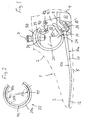
- Figure 1
- shows a resilient foot insert in a hinged artificial foot indicated in dash-dot lines in longitudinal section in the sagittal plane of the prosthesis and
- Figure 2
- a detail of Figure 1 in a modified embodiment.
Der in Figur 1 angedeutete gelenklose Kunstfuß weist eine kosmetische
Hülle 1 aus geeignetem Material auf, die einen Knöchelbereich
2, einen Fußspitzenbereich 3, einen Fersenbereich 4 und
einen Sohlenbereich 5 definiert.The hinged artificial foot indicated in FIG. 1 has a cosmetic one
Vorgesehen ist ferner eine als Blattfeder ausgebildete Basisfeder
10, die sich angenähert parallel zum Sohlenbereich 5 erstreckt
und mit ihrem vorderen Ende 12 bis in den Fußspitzenbereich
3 ragt. Die Unterseite 10a der Basisfeder 10 ist über den
größten Teil der Federlänge konvex ausgebildet.A base spring designed as a leaf spring is also provided
10, which extends approximately parallel to the
Die Basisfeder ist mit einem hinteren Ansatz 11 versehen, ausgehend
von dem die Stärke der Basisfeder 10 zu ihrem vorderen Ende
12 hin gleichmäßig abnimmt. Der hintere Ansatz 11 geht nach vorne
über in einen Sattel 14, der durch die Oberseite 10b der Basisfeder
10 definiert ist und eine Krümmung aufweist, die einen
Kreisabschnitt mit einem Mittelpunkt bei 0' darstellen kann.The base spring is provided with a rear extension 11, starting from
from which the strength of the
Zusätzlich zu der Basisfeder 10 weist der federelastische Fußeinsatz
noch eine C-Feder 20 auf, die auf dem Sattel 14 aufliegt
und mit diesem lösbar verbunden ist. Die C-Feder 20 besteht im
wesentlichen aus einem zylindrischen Segment, das eine Zylinderachse
0' definiert. Rückseitig ist die C-Feder mit einem verhältnismäßig
breiten Axialschlitz 22 versehen.In addition to the
Die Festlegung der C-Feder 20 auf dem Sattel 14 erfolgt durch
einen Schraubbolzen 26, der so angeordnet ist, daß seine Bolzenachse
15 den durch die Zylinderachse 0' definierten Mittelpunkt
des zylindrischen Segmentes der C-Feder 20 schneidet. Figur 1
läßt ferner erkennen, daß die Schraubverbindung 15, 26 gegenüber
der durch 0' verlaufenden Vertikalen D um einen Winkel α nach
hinten versetzt angeordnet ist, der zwischen 35° und 45°, vorzugsweise
aber bei 40° liegt. Die Verbindungsstelle zwischen der
C-Feder 20 und der Basisfeder 10 ist somit gegenüber der Vertikalen
D deutlich nach hinten verlagert.The C-
Der obere C-Schenkel 23 ist über ein Fesselglied 90 an einem
hinter ihm angeordneten Lagerbock 91 angelenkt, der mit dem hinteren
Ende 11 der Basisfeder 10 verbunden ist und sich auf einem
Fersenkeil 61 abstützt, der das hintere Auflager für die Basisfeder
10 bildet. Die hintere Fessellagerung 92 liegt im Achillessehnenbereich,
während die vordere Fessellagerung 93 an einer
oberen Druckplatte 34 vorgesehen ist, die an der Unterseite des
oberen C-Schenkels 23 anliegt und mit einem sich auf der Oberseite
des oberen C-Schenkels 23 abstützenden Adapter 30 verschraubt
ist. Figur 1 läßt erkennen, daß das Fesselglied 90 im
belastungsfreien Zustand angenähert parallel zur Längsachse der
Basisfeder 10 liegt.The upper C-
Das Fesselglied 90 kann aus einem textilen Gurt bestehen, der an
seinen beiden Fessellagerungen 92, 93 über je ein Kreissegment
bzw. einen Radius geführt ist. Durch die Gestaltung dieser bogenförmigen
Umleitung kann Einfluß auf die gesamte Federeigenschaft
genommen werden, da unterschiedliche Radien bei einer
Aufspreizung der C-Feder zu einer Verkürzung oder aber Verlängerung
des Fesselgliedes führen. Diese Bogenumleitungen sind daher
vorzugsweise austauschbar angeordnet. The
Um die bei Vorfußbelastung auf die C-Feder zu übertragenden Kräfte zu verringern, ist es zweckmäßig, den Lagerbock 91 unter Berücksichtigung der Gesamtkonzeption des Kunstfußes soweit wie möglich nach hinten herauszurücken.To be transferred to the C-spring when the forefoot is loaded To reduce forces, it is appropriate to under the bearing block 91 Consideration of the overall concept of the artificial foot as far as possible to move backwards.
Die C-Feder 20 kann aus Carboncomposit gefertigt sein. Es hat
sich gezeigt, daß die für die funktionell erforderliche Verformung
notwendige Dauerfestigkeit dieser C-Feder zu gering ist, um
die auftretenden Spannungen mit ausreichender Sicherheit aufnehmen
zu können. Zur Problemlösung wird die in Figur 2 dargestellte
Ausbildung der C-Feder vorgeschlagen. Bei diesem Lösungsvorschlag
setzt sich die C-Feder aus zwei parallel geschalteten C-Feder-Lamellen
20a, 20b zusammen, die ineinander gesetzt und in
ihren Endbereichen 20c unter Zwischenschaltung von Abstandshaltern
95 momentenstarr miteinander verbunden sind. Zwischen diesen
beide Endbereichen 20c weisen die beiden C-Feder-Lamellen
einen lichten radialen Abstand 94 voneinander auf. Dadurch wird
vermieden, daß sich beim Zusammendrücken der C-Feder die innere
Lamelle 20b frühzeitig an die äußere Lamelle 20a anlegt, da bei
einer Anlage die Federcharakteristik sprunghaft geändert wird.The C-
Durch die parallel geschalteten C-Federn wird eine wesentliche
Verbesserung der Strukturfestigkeit der C-Feder 20 erreicht ohne
hierdurch die Federcharakteristik zu verhindern.The parallel connected C-springs make an essential one
Improvement in the structural strength of the C-
Claims (9)
- An elastic spring foot insert for arrangement within a foot moulding (1, 2, 3, 4) of a non-articulated artificial foot for a leg prosthesis, with a C-spring (20), which is approximately C-shaped in longitudinal section and is constructed with an opening (22) at the rear, and a base spring (10), which is connected to the lower C-limb (24), is constructed as a leaf spring, extends forwards beyond the C-spring (20) approximately parallel to the sole region (5) and projects with its front end (12) into the toe region (3), characterised by the following features:a) The C-spring (20) is essentially formed by a horizontally arranged, tubular cylindrical segment, which comprises a horizontal cylinder axis (0') and an axial slot forming the said rear opening (22) ;b) the underside (10a) of the base spring (10) is predominantly convex in the region between the C-spring (20) and the free base spring end (12);c) in its rear end region, the upper side (10b) of the base spring (10) forms a saddle (14) for supportively receiving and securing a section of the lower C-limb (24);d) the upper C-limb (23) is fitted with an adapter (30) for releasable connection with a leg prosthesis;e) the upper C-limb (23) is articulatedly connected via an anchoring element (90) to a mounting block (91), which is arranged behind the upper C-limb (23) and is connected to the rear end (11) of the base spring (10).
- A foot insert according to claim 1, characterised in that the rear anchoring mount (92) provided on the mounting block (91) lies in the region of the Achilles tendon.
- A foot insert according to claim 1 or 2, characterised in that the front anchoring mount (93) is provided on an upper pressure plate (34), which rests against the underside of the upper C-limb (23) and is screwed to the adapter (30) supported on the upper side of the upper C-limb (23).
- A foot insert according to claim 1 or 2, characterised in that the front anchoring mount (93) acts directly upon the adapter (30).
- A foot insert according to one of the preceding claims, characterised in that, in the load-free state, the anchoring element (90) lies approximately parallel to the longitudinal axis of the base spring (10).
- A foot insert according to one of the preceding claims, characterised in that the anchoring element (90) is formed by a textile strap.
- A foot insert according to claim 6, characterised in that the strap forming the anchoring element (90) is guided at its two anchoring mounts (92, 93) via a preferably replaceable circular segment in each case.
- A foot insert according to one of the preceding claims, characterised in that the C-spring (20) is formed by at least two C-spring plates (20a, 20b), which are connected in parallel, are fitted one within the other and are connected to one another in a torque-free manner in their end regions (20c), whilst nevertheless comprising a clear, radial distance (94) from one another between the said end regions (20c).
- A foot insert according to claim 8, characterised in that spacing elements (95) are arranged in the end regions (20c) between the outer and the inner C-spring plates (20a, 20b).
Applications Claiming Priority (2)
| Application Number | Priority Date | Filing Date | Title |
|---|---|---|---|
| DE19717298A DE19717298C1 (en) | 1997-04-24 | 1997-04-24 | Spring-elastic foot prosthesis insert |
| DE19717298 | 1997-04-24 |
Publications (3)
| Publication Number | Publication Date |
|---|---|
| EP0885600A2 EP0885600A2 (en) | 1998-12-23 |
| EP0885600A3 EP0885600A3 (en) | 1999-01-20 |
| EP0885600B1 true EP0885600B1 (en) | 2001-10-17 |
Family
ID=7827605
Family Applications (1)
| Application Number | Title | Priority Date | Filing Date |
|---|---|---|---|
| EP98102575A Expired - Lifetime EP0885600B1 (en) | 1997-04-24 | 1998-02-14 | Elastic spring insert for artificial foot |
Country Status (8)
| Country | Link |
|---|---|
| US (1) | US6077301A (en) |
| EP (1) | EP0885600B1 (en) |
| CN (1) | CN1135099C (en) |
| AT (1) | ATE206903T1 (en) |
| CA (1) | CA2234290C (en) |
| DE (2) | DE19717298C1 (en) |
| RU (1) | RU2192811C2 (en) |
| TW (1) | TW407051B (en) |
Families Citing this family (43)
| Publication number | Priority date | Publication date | Assignee | Title |
|---|---|---|---|---|
| US20020087216A1 (en) * | 1996-02-16 | 2002-07-04 | Atkinson Stewart L. | Prosthetic walking system |
| US6187052B1 (en) * | 1999-07-14 | 2001-02-13 | Joseph L. Molino | Prosthetic ankle joint |
| US20050216098A1 (en) * | 2000-06-30 | 2005-09-29 | Roland J. Christensen | Variable resistance cell |
| US20060241783A1 (en) * | 2000-06-30 | 2006-10-26 | Christensen Roland J | Variable resistance cell |
| US7572299B2 (en) * | 2000-06-30 | 2009-08-11 | Freedom Innovations, Llc | Prosthetic foot with energy transfer |
| US7341603B2 (en) * | 2000-06-30 | 2008-03-11 | Applied Composite Technology, Inc. | Prosthetic foot with energy transfer including variable orifice |
| US7686848B2 (en) * | 2000-06-30 | 2010-03-30 | Freedom Innovations, Llc | Prosthetic foot with energy transfer |
| DE10049714B4 (en) * | 2000-10-07 | 2004-11-11 | Otto Bock Orthopädische Industrie Besitz-und Verwaltungs GmbH & Co.KG | Foot insert for an artificial foot |
| US7410503B2 (en) * | 2001-03-30 | 2008-08-12 | Bioquest Prosthetics Llc | Prosthetic foot with tunable performance |
| US7611543B2 (en) | 2001-03-30 | 2009-11-03 | Bioquest Prosthetics, Llc | Prosthetic foot with tunable performance |
| US6562075B2 (en) | 2001-03-30 | 2003-05-13 | Barry W. Townsend | Prosthetic foot with tunable performance |
| WO2002051341A1 (en) * | 2000-12-27 | 2002-07-04 | S.P. Korolev Rocket And Space Public Corporation Energia | Artificial foot |
| US7578852B2 (en) * | 2001-03-30 | 2009-08-25 | Bioquest Prosthetics, Llc | Prosthetic foot with tunable performance and improved vertical load/shock absorption |
| US8070829B2 (en) | 2003-09-30 | 2011-12-06 | Bioquest Prosthetics Llc | Prosthetic foot with tunable performance |
| US20070213841A1 (en) * | 2001-03-30 | 2007-09-13 | Townsend Barry W | Prosthetic foot with tunable performance |
| US7429272B2 (en) | 2001-03-30 | 2008-09-30 | Bioquest Prosthetics Llc | Prosthetic foot with tunable performance |
| US7507259B2 (en) * | 2001-03-30 | 2009-03-24 | Bioquest Prosthetics, Llc | Prosthetic foot with tunable performance |
| US8236062B2 (en) | 2001-03-30 | 2012-08-07 | Bioquest Prosthetics Llc | Prosthetic foot with tunable performance |
| US7374578B2 (en) | 2001-03-30 | 2008-05-20 | Bioquest Prosthetics, Llc | Prosthetic foot with tunable performance |
| US6764521B2 (en) | 2001-08-24 | 2004-07-20 | Joseph L. Molino | Multi-axial ankle joint |
| US8574314B2 (en) * | 2003-09-30 | 2013-11-05 | Bioquest Prosthetics Llc | Resilient prosthetic and orthotic components which incorporate a plurality of sagittally oriented struts |
| US7520904B2 (en) * | 2003-10-21 | 2009-04-21 | Freedom Innovations, Llc | Prosthetic foot with an adjustable ankle and method |
| EP1729699A4 (en) | 2004-04-01 | 2010-01-27 | Barry W Townsend | Prosthetic foot with tunable performance |
| US20060173555A1 (en) * | 2005-02-02 | 2006-08-03 | Chuen-Sen Harn | Elastic energy-stored artificial foot |
| US7618464B2 (en) * | 2006-08-03 | 2009-11-17 | Freedom Innovations, Llc | Prosthetic foot with variable medial/lateral stiffness |
| US7824446B2 (en) * | 2006-12-06 | 2010-11-02 | Freedom Innovations, Llc | Prosthetic foot with longer upper forefoot and shorter lower forefoot |
| US7727285B2 (en) * | 2007-01-30 | 2010-06-01 | Freedom Innovations, Llc | Prosthetic foot with variable medial/lateral stiffness |
| US7794506B2 (en) * | 2007-09-18 | 2010-09-14 | Freedom Innovations, Llc | Multi-axial prosthetic ankle |
| US11020248B2 (en) | 2007-09-19 | 2021-06-01 | Proteor USA, LLC | Vacuum system for a prosthetic foot |
| US10405998B2 (en) | 2007-09-19 | 2019-09-10 | Ability Dynamics Llc | Mounting bracket for connecting a prosthetic limb to a prosthetic foot |
| US8034121B2 (en) | 2008-04-18 | 2011-10-11 | Freedom Innovations, Llc | Prosthetic foot with two leaf-springs joined at heel and toe |
| US9011554B2 (en) * | 2008-07-25 | 2015-04-21 | Fillauer Composites Llc | High-performance multi-component prosthetic foot |
| US8500825B2 (en) | 2010-06-29 | 2013-08-06 | Freedom Innovations, Llc | Prosthetic foot with floating forefoot keel |
| EP2760379B1 (en) | 2011-09-26 | 2017-10-25 | Össur HF | Frictionless vertical suspension mechanism for prosthetic feet |
| US9017421B2 (en) | 2011-12-01 | 2015-04-28 | össur hf | Prosthetic foot with dual foot blades and vertically offset toe |
| WO2014022411A1 (en) | 2012-08-01 | 2014-02-06 | Ossur Hf | Prosthetic ankle module |
| CN106659573B (en) | 2014-06-30 | 2019-08-27 | 奥苏尔公司 | Pseudopod and foot covering |
| EP3244841A4 (en) | 2015-01-15 | 2018-09-12 | Ability Dynamics, LLC | Prosthetic foot |
| USD795433S1 (en) | 2015-06-30 | 2017-08-22 | Össur Iceland Ehf | Prosthetic foot cover |
| EP3290006B1 (en) * | 2016-08-30 | 2024-01-24 | Fillauer Europe AB | Prosthetic device |
| US10927915B2 (en) * | 2017-12-15 | 2021-02-23 | Otis Elevator Company | Spring useful for elevator safety device |
| USD915596S1 (en) | 2018-04-10 | 2021-04-06 | Össur Iceland Ehf | Prosthetic foot with tapered fasteners |
| CN109199653B (en) * | 2018-10-09 | 2020-07-21 | 广东兰湾智能科技有限公司 | Artificial limb foot |
Family Cites Families (16)
| Publication number | Priority date | Publication date | Assignee | Title |
|---|---|---|---|---|
| DE8804228U1 (en) * | 1988-03-29 | 1988-05-05 | Ipos Gmbh & Co Kg, 2120 Lueneburg, De | |
| US4959073A (en) * | 1988-06-06 | 1990-09-25 | John Merlette | Foot prosthesis and method of making same |
| FR2640499A1 (en) * | 1988-12-15 | 1990-06-22 | Palfray Michel | Novel prosthetic foot structure |
| US5037444A (en) * | 1989-01-05 | 1991-08-06 | Phillips L Van | Prosthetic foot |
| US5139525A (en) * | 1989-07-31 | 1992-08-18 | Kristinsson Oessur | Prosthetic foot |
| DE4037928A1 (en) * | 1990-11-24 | 1992-05-27 | Hms Antriebssysteme Gmbh | Jointless artificial foot - has spring-elastic foot insert formed at ring spring conforming to natural outer foot contour |
| DE4038063C2 (en) * | 1990-11-29 | 1995-04-20 | Bock Orthopaed Ind | Articulated prosthetic foot |
| US5258039A (en) * | 1991-11-15 | 1993-11-02 | The National University Of Singapore | Energy storing composite prosthetic foot |
| WO1994010942A1 (en) * | 1992-10-11 | 1994-05-26 | Composites-Busch & Cie | Foot prosthesis |
| WO1994010943A1 (en) * | 1992-11-17 | 1994-05-26 | Allen Scott E | Coil spring prosthetic foot |
| US5443528A (en) * | 1992-11-17 | 1995-08-22 | Allen; Scott | Coil spring prosthetic foot |
| US5653767A (en) * | 1992-11-17 | 1997-08-05 | Medonics, Llc | Prosthetic foot |
| DE9315665U1 (en) * | 1993-10-14 | 1993-12-09 | Ipos Gmbh & Co Kg | Ankle spring element for prosthetic legs and artificial foot |
| TW386434U (en) * | 1994-08-15 | 2000-04-01 | L Van Phillips | Prosthesis with foam block ankle |
| FR2734151B1 (en) * | 1995-05-15 | 1997-11-14 | Corima | REACTIVE STRUCTURE OF PROSTHETIC FOOT |
| FR2745488B1 (en) * | 1996-03-04 | 1998-07-31 | Corima | REACTIVE FOOT PROSTHESIS |
-
1997
- 1997-04-24 DE DE19717298A patent/DE19717298C1/en not_active Expired - Fee Related
-
1998
- 1998-02-14 AT AT98102575T patent/ATE206903T1/en not_active IP Right Cessation
- 1998-02-14 DE DE59801741T patent/DE59801741D1/en not_active Expired - Lifetime
- 1998-02-14 EP EP98102575A patent/EP0885600B1/en not_active Expired - Lifetime
- 1998-03-02 TW TW087102960A patent/TW407051B/en not_active IP Right Cessation
- 1998-03-16 RU RU98105505/14A patent/RU2192811C2/en active
- 1998-03-23 CN CNB98105756XA patent/CN1135099C/en not_active Expired - Lifetime
- 1998-04-08 CA CA002234290A patent/CA2234290C/en not_active Expired - Lifetime
- 1998-04-22 US US09/064,093 patent/US6077301A/en not_active Expired - Lifetime
Also Published As
| Publication number | Publication date |
|---|---|
| DE19717298C1 (en) | 1998-05-07 |
| EP0885600A2 (en) | 1998-12-23 |
| RU2192811C2 (en) | 2002-11-20 |
| CA2234290C (en) | 2005-01-25 |
| TW407051B (en) | 2000-10-01 |
| EP0885600A3 (en) | 1999-01-20 |
| DE59801741D1 (en) | 2001-11-22 |
| CN1135099C (en) | 2004-01-21 |
| ATE206903T1 (en) | 2001-11-15 |
| US6077301A (en) | 2000-06-20 |
| CN1196916A (en) | 1998-10-28 |
| CA2234290A1 (en) | 1998-10-24 |
Similar Documents
| Publication | Publication Date | Title |
|---|---|---|
| EP0885600B1 (en) | Elastic spring insert for artificial foot | |
| EP0793949B1 (en) | Jointless artificial foot | |
| DE10049714B4 (en) | Foot insert for an artificial foot | |
| DE3808994C2 (en) | Lower leg prosthesis | |
| DE60317775T2 (en) | RAIL FOR AN EAST OTHRITAN KNEE | |
| DE102004037877B4 (en) | Foot prosthesis | |
| DE2849588C2 (en) | Prosthetic joint | |
| EP0487852B1 (en) | Jointless prosthetic foot | |
| DE60208889T2 (en) | FUSSGELENKSORTHOSE | |
| DE60002875T2 (en) | LOWER LEG PROSTHESIS | |
| EP0407650B1 (en) | Artificial foot for a leg prothesis | |
| EP0334989A2 (en) | Artificial foot for a leg prosthesis | |
| EP3139869A1 (en) | Prosthetic foot | |
| DE10053259A1 (en) | Foot prosthesis comprises ankle section, several intermediate curved sections and sole section which jointly make up integral leaf spring structure | |
| EP0648479A1 (en) | Ankle spring module for leg prosthesis or artificial foot | |
| DE2341887B2 (en) | Artificial foot for a prosthetic leg | |
| DE10393458B4 (en) | Foot prosthesis with elastic ankle and oblique attachment | |
| WO2020152339A1 (en) | Prosthetic foot component | |
| EP3914196A1 (en) | Prosthetic foot component | |
| WO2005117772A1 (en) | Orthesis | |
| EP1072240B1 (en) | Hip joint for an artificial leg | |
| DE102010049257B4 (en) | prosthetic | |
| DE102016105704B4 (en) | Base body for a prosthetic foot and prosthetic foot with it | |
| DE4208941A1 (en) | Foot prosthesis with curved ankle part - has detachable heel part fastened to ankle part | |
| CH719427A1 (en) | Lower leg orthosis. |
Legal Events
| Date | Code | Title | Description |
|---|---|---|---|
| PUAI | Public reference made under article 153(3) epc to a published international application that has entered the european phase |
Free format text: ORIGINAL CODE: 0009012 |
|
| PUAL | Search report despatched |
Free format text: ORIGINAL CODE: 0009013 |
|
| AK | Designated contracting states |
Kind code of ref document: A2 Designated state(s): AT CH DE FR GB IT LI NL SE |
|
| AX | Request for extension of the european patent |
Free format text: AL;LT;LV;MK;RO;SI |
|
| AK | Designated contracting states |
Kind code of ref document: A3 Designated state(s): AT BE CH DE DK ES FI FR GB GR IE IT LI LU MC NL PT SE |
|
| AX | Request for extension of the european patent |
Free format text: AL;LT;LV;MK;RO;SI |
|
| 17P | Request for examination filed |
Effective date: 19990126 |
|
| AKX | Designation fees paid |
Free format text: AT CH DE FR GB IT LI NL SE |
|
| GRAG | Despatch of communication of intention to grant |
Free format text: ORIGINAL CODE: EPIDOS AGRA |
|
| 17Q | First examination report despatched |
Effective date: 20010504 |
|
| GRAG | Despatch of communication of intention to grant |
Free format text: ORIGINAL CODE: EPIDOS AGRA |
|
| GRAH | Despatch of communication of intention to grant a patent |
Free format text: ORIGINAL CODE: EPIDOS IGRA |
|
| GRAA | (expected) grant |
Free format text: ORIGINAL CODE: 0009210 |
|
| AK | Designated contracting states |
Kind code of ref document: B1 Designated state(s): AT CH DE FR GB IT LI NL SE |
|
| REF | Corresponds to: |
Ref document number: 206903 Country of ref document: AT Date of ref document: 20011115 Kind code of ref document: T |
|
| REG | Reference to a national code |
Ref country code: CH Ref legal event code: NV Representative=s name: BRAUN & PARTNER PATENT-, MARKEN-, RECHTSANWAELTE Ref country code: CH Ref legal event code: EP |
|
| REF | Corresponds to: |
Ref document number: 59801741 Country of ref document: DE Date of ref document: 20011122 |
|
| REG | Reference to a national code |
Ref country code: GB Ref legal event code: IF02 |
|
| GBT | Gb: translation of ep patent filed (gb section 77(6)(a)/1977) |
Effective date: 20020122 |
|
| ET | Fr: translation filed | ||
| RAP2 | Party data changed (patent owner data changed or rights of a patent transferred) |
Owner name: OTTO BOCK HEALTHCARE GMBH |
|
| PLBE | No opposition filed within time limit |
Free format text: ORIGINAL CODE: 0009261 |
|
| STAA | Information on the status of an ep patent application or granted ep patent |
Free format text: STATUS: NO OPPOSITION FILED WITHIN TIME LIMIT |
|
| NLT2 | Nl: modifications (of names), taken from the european patent patent bulletin |
Owner name: OTTO BOCK HEALTHCARE GMBH |
|
| 26N | No opposition filed | ||
| PGFP | Annual fee paid to national office [announced via postgrant information from national office to epo] |
Ref country code: AT Payment date: 20060222 Year of fee payment: 9 |
|
| PGFP | Annual fee paid to national office [announced via postgrant information from national office to epo] |
Ref country code: CH Payment date: 20060301 Year of fee payment: 9 |
|
| PG25 | Lapsed in a contracting state [announced via postgrant information from national office to epo] |
Ref country code: LI Free format text: LAPSE BECAUSE OF NON-PAYMENT OF DUE FEES Effective date: 20070228 Ref country code: CH Free format text: LAPSE BECAUSE OF NON-PAYMENT OF DUE FEES Effective date: 20070228 |
|
| REG | Reference to a national code |
Ref country code: CH Ref legal event code: PL |
|
| PG25 | Lapsed in a contracting state [announced via postgrant information from national office to epo] |
Ref country code: AT Free format text: LAPSE BECAUSE OF NON-PAYMENT OF DUE FEES Effective date: 20070214 |
|
| REG | Reference to a national code |
Ref country code: DE Ref legal event code: R082 Ref document number: 59801741 Country of ref document: DE Representative=s name: GRAMM, LINS & PARTNER PATENT- UND RECHTSANWAEL, DE |
|
| REG | Reference to a national code |
Ref country code: FR Ref legal event code: PLFP Year of fee payment: 19 |
|
| REG | Reference to a national code |
Ref country code: FR Ref legal event code: PLFP Year of fee payment: 20 |
|
| PGFP | Annual fee paid to national office [announced via postgrant information from national office to epo] |
Ref country code: FR Payment date: 20170220 Year of fee payment: 20 Ref country code: DE Payment date: 20170222 Year of fee payment: 20 Ref country code: SE Payment date: 20170221 Year of fee payment: 20 |
|
| PGFP | Annual fee paid to national office [announced via postgrant information from national office to epo] |
Ref country code: GB Payment date: 20170221 Year of fee payment: 20 Ref country code: NL Payment date: 20170220 Year of fee payment: 20 |
|
| PGFP | Annual fee paid to national office [announced via postgrant information from national office to epo] |
Ref country code: IT Payment date: 20170217 Year of fee payment: 20 |
|
| REG | Reference to a national code |
Ref country code: DE Ref legal event code: R071 Ref document number: 59801741 Country of ref document: DE Ref country code: NL Ref legal event code: MK Effective date: 20180213 |
|
| REG | Reference to a national code |
Ref country code: GB Ref legal event code: PE20 Expiry date: 20180213 |
|
| PG25 | Lapsed in a contracting state [announced via postgrant information from national office to epo] |
Ref country code: GB Free format text: LAPSE BECAUSE OF EXPIRATION OF PROTECTION Effective date: 20180213 |