EP0793938A2 - Staubsaugerdüse mit federnder Gleitsohle - Google Patents
Staubsaugerdüse mit federnder Gleitsohle Download PDFInfo
- Publication number
- EP0793938A2 EP0793938A2 EP97101554A EP97101554A EP0793938A2 EP 0793938 A2 EP0793938 A2 EP 0793938A2 EP 97101554 A EP97101554 A EP 97101554A EP 97101554 A EP97101554 A EP 97101554A EP 0793938 A2 EP0793938 A2 EP 0793938A2
- Authority
- EP
- European Patent Office
- Prior art keywords
- sliding sole
- vacuum cleaner
- nozzle
- cleaner nozzle
- nozzle according
- Prior art date
- Legal status (The legal status is an assumption and is not a legal conclusion. Google has not performed a legal analysis and makes no representation as to the accuracy of the status listed.)
- Granted
Links
- 125000006850 spacer group Chemical group 0.000 claims description 14
- 238000007789 sealing Methods 0.000 claims description 3
- 230000006978 adaptation Effects 0.000 description 4
- 230000015572 biosynthetic process Effects 0.000 description 2
- 238000004140 cleaning Methods 0.000 description 2
- 230000000295 complement effect Effects 0.000 description 2
- 230000000694 effects Effects 0.000 description 2
- 238000007654 immersion Methods 0.000 description 2
- 230000001419 dependent effect Effects 0.000 description 1
- 229920001971 elastomer Polymers 0.000 description 1
- 239000000806 elastomer Substances 0.000 description 1
- 239000000835 fiber Substances 0.000 description 1
- 239000006260 foam Substances 0.000 description 1
- 229920001821 foam rubber Polymers 0.000 description 1
- 239000004576 sand Substances 0.000 description 1
- 239000000758 substrate Substances 0.000 description 1
- 239000000725 suspension Substances 0.000 description 1
Images


Classifications
-
- A—HUMAN NECESSITIES
- A47—FURNITURE; DOMESTIC ARTICLES OR APPLIANCES; COFFEE MILLS; SPICE MILLS; SUCTION CLEANERS IN GENERAL
- A47L—DOMESTIC WASHING OR CLEANING; SUCTION CLEANERS IN GENERAL
- A47L9/00—Details or accessories of suction cleaners, e.g. mechanical means for controlling the suction or for effecting pulsating action; Storing devices specially adapted to suction cleaners or parts thereof; Carrying-vehicles specially adapted for suction cleaners
- A47L9/02—Nozzles
Definitions
- the invention relates to a vacuum cleaner nozzle with a nozzle housing in which a sliding sole is arranged such that it is movable and resilient.
- vacuum cleaner nozzles have to be designed in such a way that they fulfill their main task, the suction of dirt, sand and fibers.
- sliding soles of vacuum cleaner nozzles are designed such that they are firmly fixed in the nozzle body and slide on so-called sliding or sliding bodies or elements over the floor to be cleaned. It is known to form elevations on the underside of the sliding sole which serve as sliding bodies. It is also known to arrange sliding elements on the sliding sole or in the sliding sole, such as, for example, small rollers which are integrated in the suction channel and are thus flush with the underside of the sliding sole. It is important and to ensure an optimal cleaning effect, in addition to the design of the flow channels, the formation of the sliding sole itself, so that optimal contact of the sliding sole with the floor is guaranteed, even under different suction conditions.
- the size, body height and thus the gripping height of the operator also play an important role in ensuring that the sliding sole has optimal contact with the floor.
- the pile height and pile density of the carpet must be taken into account, all vacuum cleaner nozzles are articulated.
- this articulated arrangement is realized by means of a tilting joint, which is arranged centrally above the sliding sole.
- This has the disadvantage that all suction forces are directed onto the sliding sole and very high pushing forces are thereby generated.
- it is already known to hold the sliding sole itself in a tiltable or elastic manner.
- these suction forces are intercepted by rollers arranged behind the nozzle or at the rear end of the nozzle body, the roller axis usually also being the axis of the joint at the same time.
- These rotary-tilt joints absorb a large part of the pushing forces, such as those e.g. caused by changing grip heights, but cannot ensure optimum ground contour following, ie no optimal contact with the ground, if the sliding sole is rigidly arranged.
- the resilient arrangement of the sliding sole is realized in that the sliding sole is arranged at at least two fixed points on the nozzle housing in such a way that it is horizontal and / or can perform vertical wobble. Due to the arrangement at at least two fixed points, which are designed in the manner of spacer bolts and extend between the nozzle housing and the sliding sole, the sliding sole can tilt and move in several directions in order to adapt optimally to the ground. In addition, thanks to its all-round mobility, the sliding sole can compensate for larger unevenness in the floor, such as waves, channels, carpets with high and low structures, and thus always maintains optimal contact with the floor on carpets and smooth floors.
- the fixed points on the nozzle housing, at which the sliding sole is arranged movably lie opposite one another on a longitudinal axis of the nozzle housing or diagonally opposite one another on the nozzle housing with respect to one of the longitudinal axes.
- the fixed points on the nozzle housing are designed in the manner of spacer elements which extend between the nozzle housing and the sliding sole.
- the spacer elements are screwed or snapped into the nozzle housing, that is to say firmly fixed in such a way that the part of the spacer element carrying the sliding sole protrudes from the fixation and the sliding sole protrudes through a recess provided for this purpose in such a way that the spacing is defined both horizontally and / or can move vertically.
- the sliding sole is at a defined distance, ie the distance between the stop on the fixed point or the spacer element and a further stop, which can also be arranged on the spacer element or a stop arranged within the structures of the nozzle housing and thus limits the path of the sliding sole towards the nozzle body.
- Both the stops which are arranged within the nozzle housing and the stops on the spacer elements which extend between the nozzle body and the sliding sole are arranged such that they can lie both in one plane and in mutually different planes, so that they each differ from one another Define movement distances.
- the stops are to be arranged in such a way that all-round mobility is achieved in predetermined angular amounts of preferably 5 ° to 15 °.
- the stops which limit both the horizontal and the vertical wobble movement of the articulated sliding sole, are each spaced such that the sliding sole wobbles at an angle of 10 to 15 ° around the imaginary longitudinal axis.
- An elastic intermediate layer can be sealingly inserted between the sliding sole and the nozzle body, which in turn also permits mobility in predetermined angular amounts.
- This elastic intermediate layer is formed in particular from foam, foam rubber or as an elastomer bellows. As a rule, these intermediate layers are sealed.
- the elastomeric bellows extends between the sliding sole and the nozzle body directly on the suction channel, so that this generally additionally seals.
- a so-called wobble movement or floating suspension of the sliding sole can be realized by the articulation or arrangement of the sliding sole at at least one fixed point.
- Each of the individual fixed points can allow a defined movement of the sliding sole by means of stops. If, for example, the sliding sole is not articulated at one but at four fixed points, of which the individual allows a defined movement distance that is independent of the other fixed point, the sliding sole performs a kind of wobble movement.
- springs arranged on the spacer elements or between the sliding sole and the nozzle housing keep the sliding sole in a defined starting position, from which it can be deflected by the forces occurring during suction.
- This defined starting position can also be defined via an elastic intermediate layer inserted between the sliding sole and the nozzle body.
- the suction mouth of the suction channel can be formed with suction mouth edges which are held individually and independently of one another in a vertically resilient manner. These suction mouth edges are spring-mounted so that they deflect to a state of equilibrium due to the weight of the nozzles and the vertical force generated by the suction vacuum, and thus optimally adapt to the surface.
- the Suction mouth edges can be arranged on the suction channel or suction mouth via elements with differentiated return spring force. In particular, the spring force of the suction mouth edges behind the suction mouth is variably adjustable.
- the edges of the suction mouth make it possible for the edges of the suction mouth to adapt to the substrate both about the longitudinal axis of the nozzle and for them to be immersed at different immersion depths, for example in pile carpets.
- the spring forces of the suction mouth edge behind the suction mouth can be variably adjusted and changed in order to be able to vary the immersion depth of this rear suction mouth edge depending on the surface to be vacuumed.
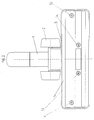
- the nozzle body 3 has a sliding sole 4, on the side facing the floor of which the sliding sole 4 is arranged on the nozzle body via fixed points 5 and 5a.
- the fixed points 5 and 5a are designed as stop elements which engage in complementary elements within the nozzle body such that the sliding sole 4 is movably connected to the nozzle body at a defined distance via the fixed points 5 and 5a.
- the fixed points 5 and 5a for locking the sliding sole are arranged at least substantially diagonally with respect to one another with respect to the imaginary central axis of the vacuum cleaner nozzle.
- the fixed points are arranged diagonally in such a way that a fixed point 5a is arranged directly next to the suction channel, lying in the flow channel, and a further fixed point is arranged near the outer edge of the sliding sole, behind the flow channel of the vacuum cleaner nozzle.
- FIG. 2 shows a vacuum cleaner nozzle according to FIG. 1 with an intake port 1, with rollers 2 arranged behind the nozzle body, with a nozzle housing 3 and a sliding sole 4, which has four fixed points 5, 5a, 5b, 5c on the nozzle body 3 is arranged movably.
- the fixed points 5b and 5a lie on both sides of the suction channel in one plane in the flow channel and the fixed points 5 and 5c behind the flow channel on the outer edges of the sliding sole in one plane, opposite one another.
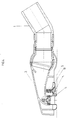
- Fig. 3 shows a schematic representation of the section through a vacuum cleaner nozzle with a suction pipe connection piece 1, which is connected to the nozzle body 3 via a rotary-tilt joint.
- the sliding sole 4 is again connected to the nozzle body 3 via the fixed point 5, which is designed in the form of a spacer element, a spacer bolt.
- the fixed point 5 engages in a complementary recess which protrudes from the nozzle body in the direction of the sliding sole.
- the fixed point 5 has a type of screw head for holding the sliding sole, to which a cylindrical bolt adjoins, which is arranged at a defined distance from the recess 8 receiving the bolt in the form of a receiving sleeve.
- the sliding sole 4 is sealed by means of sealing elements 9 which is designed in the manner of a bellows which extends stretchably between the suction channel and the sliding sole. This bellows is deformed accordingly by the vertical or horizontal movement of the sliding sole 4 at the fixed points 5, that is to say compressed or stretched, so that a seal against the suction channel is ensured over the entire movement sequence of the sliding sole.
- Fig. 4 shows a schematic sectional view of a vacuum cleaner nozzle with a suction pipe connection piece 1 and a nozzle housing 3, to which a sliding sole 4 is articulated horizontally and vertically by means of several fixed points 5.
- the fixed points 5 are arranged directly on the suction channel and in the flow channel.
- a return spring 10 is arranged between the sliding sole 4 and the inner structure of the nozzle housing around one of the fixed points. With its restoring force, the return spring ensures that the sliding sole is pressed onto the floor or onto the pile, even when the sliding sole is positioned vertically or horizontally, in order to ensure maximum contact with the floor.
Landscapes
- Engineering & Computer Science (AREA)
- Mechanical Engineering (AREA)
- Nozzles For Electric Vacuum Cleaners (AREA)
Abstract
Description
- Die Erfindung betrifft eine Staubsaugerdüse mit einem Düsengehäuse, in welchem eine Gleitsohle beweglich federnd angeordnet ist.
- Zur Gewährleistung eines optimalen Reinigungseffektes gilt es Staubsaugerdüsen so auszugestalten, daß sie ihre Hauptaufgabe, das Absaugen von Schmutz, Sand und Fasern optimal erfüllen, wobei dieses wirkungsvolle Absaugen der Schmutzpartikel bei geringem Energiebedarf des Saugers und mit geringem Kraftaufwand des den Sauger Bedienenden erfolgen soll.
- In der Regel sind Gleitsohlen von Staubsaugerdüsen so ausgebildet, daß sie fest im Düsenkörper fixiert sind und auf sogenannten Gleit- oder Rutschkörpern bzw. -elementen über den zu reinigenden Boden gleiten. Bekannt ist dabei, an der Gleitsohlenunterseite Erhebungen einzuformen die als Gleitkörper dienen. Bekannt ist es ebenfalls, an der Gleitsohle bzw. in der Gleitsohle Gleitelemente, wie beispielsweise kleine Laufrollen die im Saugkanal integriert sind und somit bündig mit der Gleitsohlenunterseite abschließen, anzuordnen. Wichtig und zur Gewährleistung eines optimalen Reinigungseffektes ist neben der Gestaltung der Strömungskanäle die Ausbildung der Gleitsohle selbst, so daß ein stets optimaler Bodenkontakt der Gleitsohle zum Boden, auch bei unterschiedlichen Saugbedingungen, gewährleistet wird.
- Neben der Bodenbeschaffenheit spielt auch die Größe, die Körperhöhe und damit die Greifhöhe des Bedieners eine wichtige Rolle für den optimalen Bodenkontakt der Gleitsohle. Um diesen optimalen Bodenkontakt bei allen Bauformen von Staubsaugerdüsen zu gewährleisten, ist zum Ausgleich der Bogenbahn der Hand beim Saugen und zum Ausgleichen des unterschiedlichen Einsinkens der Gleitsohle auf verschiedenen Bodenbelägen, hier sind insbesondere Florhöhe und Flordichte des Teppichs zu beachten, sind alle Staubsaugerdüsen gelenkig angeordnet.
- In der Regel wird diese gelenkige Anordnung über ein Kippgelenk realisiert, das mittig über der Gleitsohle angeordnet ist. Dies hat den Nachteil, daß alle Saugkräfte auf die Gleitsohle geleitet und dadurch sehr hohe Schiebekräfte erzeugt werden. Um diese Nachteile auszuräumen ist es bereits bekannt die Gleitsohle selbst kippbar oder elastisch zu haltern. Bei neueren moderneren Bauformen von Staubsaugerdüsen werden diese Saugkräfte durch hinter der Düse oder am hinteren Ende des Düsenkörpers angeordnete Laufrollen abgefangen, wobei die Rollenachse meist gleichzeitig auch die Achse des Gelenkes ist. Diese Dreh-Kipp-Gelenke fangen zwar ein Großteil der Schiebekräfte ab, wie sie z.B. durch wechselnde Griffhohe entstehen, können jedoch bei starrer Anordnung der Gleitsohle keine optimale Bodenanpassung, also keinen optimalen Bodenkontakt gewährleisten.
- Zur optimalen Bodenanpassung der Gleitsohle ist es bekannt, die Gleitsohle teilweise auch als schmalen Saugmund ausgebildet oder den gesamten Düsenkörper inklusive Gleitsohle über ein zweites Kippgelenk, das mit deutlichem Abstand von den Laufrollen und den ersten Dreh-Kipp-Gelenk angeordnet ist kippbar zu haltern. Diese Bauformen gewährleisten zwar eine optimale Bodenanpassung der Gleitsohle sind jedoch von der technischen Ausbildung äußerst aufwendig und damit kostenintensiv.
- Ausgehend von diesen Nachteilen ist es die Aufgabe der Erfindung eine Gleitsohle mit optimaler Bodenanpassung zu schaffen, welche ohne Ausbildung eines zweiten Kippgelenkes innerhalb der Staubsaugerdüse diese optimale Bodenanpassung der Gleitsohle ermöglicht.
- Erfindungsgemäß wird diese Aufgabe durch das Kennzeichen des Patentanspruchs 1 gelöst. Weitere bevorzugte Ausführungsformen dieser Staubsaugerdüse sind Gegenstand der abhängigen Unteransprüche.
- Die federnde Anordnung der Gleitsohle, so daß diese jeweils plan auf der zu reinigenden Fläche aufliegt wird dadurch realisiert, daß die Gleitsohle an mindestens zwei Fixpunkten am Düsengehäuse so angeordnet ist, daß sie eine horizontale und/oder vertikale Taumelbewegung ausführen kann. Aufgrund der Anordnung an mindestens zwei Fixpunkten, die nach Art von Abstandsbolzen ausgebildet sind und sich zwischen Düsengehäuse und Gleitsohle erstrecken kann sich die Gleitsohle in mehrere Richtungen neigen und bewegen, um sich so dem Untergrund jeweils optimal anzupassen. Außerdem kann die Gleitsohle durch ihre allseitige Beweglichkeit größere Bodenunebenheiten wie beispielsweise Wellen, Rinnen, Teppiche mit Hoch- und Tiefstruktur ausgleichen und behält so auf Teppich, wie auf Glattböden stets optimalen Bodenkontakt. Die Fixpunkte am Düsengehäuse, an welchen die Gleitsohle beweglich angeordnet ist, liegen auf einer Längsachse des Düsengehäuses einander gegenüberliegend oder hinsichtlich einer der Längsachsen diagonal einander gegenüberliegend am Düsengehäuse.
- Diese Anordnung der Fixpunkte ermöglicht eine allseitige Beweglichkeit der Gleitsohle bis zum jeweiligen Anschlag. Die Fixpunkte am Düsengehäuse sind nach Art von Abstandselementen ausgebildet, die sich zwischen Düsengehäuse und Gleitsohle erstrecken. Die Abstandselemente sind dabei in das Düsengehäuse eingeschraubt oder eingeschnappt, also fest so fixiert, daß der die Gleitsohle tragende Teil des Abstandselementes aus der Fixierung herausragt und die Gleitsohle an einer entsprechend dafür vorgesehenen Ausnehmung so durchragt, daß die sich in entsprechend definiertem Abstand sowohl horizontal und/oder vertikal bewegen kann. Damit ist gewährleistet, daß sich die Gleitsohle in einem definiertem Abstand, also dem Abstand zwischen dem Anschlag auf dem Fixpunkt bzw. dem Abstandselement und einem weiteren Anschlag, der ebenfalls auf dem Abstandselement angeordnet sein kann bzw. einem Anschlag der innerhalb der Strukturen des Düsengehäuses angeordnet ist und damit den Weg der Gleitsohle in Richtung Düsenkörper begrenzt, bewegen kann. Sowohl die Anschläge die innerhalb des Düsengehäuses angeordnet sind, als auch die Anschläge an den Abstandselementen, die sich zwischen Düsenkörper und Gleitsohle erstrecken sind so angeordnet, daß sie sowohl in einer Ebene als auch in voneinander abweichenden Ebenen liegen können, so daß sie jeweils voneinander abweichende Bewegungsabstände definieren.
- In der Regel sind die Anschläge so anzuordnen, daß die allseitige Beweglichkeit in vorbestimmten Winkelbeträgen von vorzugsweise 5° bis 15° realisiert wird. Mit anderen Worten, die Anschläge, welche sowohl die horizontale als auch die vertikale Taumelbewegung der angelenkten Gleitsohle begrenzen, sind jeweils so beabstandet, daß die Gleitsohle in einem Winkel von 10 bis 15° um die gedachte Längsachse taumelt. Zwischen Gleitsohle und Düsenkörper kann eine elastische Zwischenlage dichtend eingebracht sein, welche ihrerseits ebenfalls die Beweglichkeit in vorbestimmten Winkelbeträgen zuläßt. Diese elastische Zwischenlage ist insbesondere aus Schaumstoff, Moosgummi oder als Elastomerfaltenbalg ausgebildet. In der Regel sind diese Zwischenlagen dichtend eingebracht. Insbesondere der Elastomerfaltenbalg erstreckt sich zwischen Gleitsohle und Düsenkörper unmittelbar am Saugkanal, so daß dieser in der Regel zusätzlich abdichtet. Durch die Anlenkung bzw. Anordnung der Gleitsohle an mindestens einem Fixpunkt kann eine sogenannte Taumelbewegung bzw. schwimmende Aufhängung der Gleitsohle realisiert werden. Jeder der einzelnen Fixpunkte kann durch Anschläge eine definierte Bewegung der Gleitsohle ermöglichen. Wird die Gleitsohle beispielsweise nicht an einem sondern an vier Fixpunkten angelenkt von denen der einzelne einen vom anderen Fixpunkt unabhängigen definierten Bewegungsabstand zuläßt, führt die Gleitsohle eine Art Taumelbewegung aus. Zusätzlich auf den Abstandselementen bzw. zwischen Gleitsohle und Düsengehäuse angeordnete Federn halten die Gleitsohle in einer definierten Ausgangsposition, aus welcher sie durch die beim Saugen auftretenden Kräfte ausgelenkt werden kann. Diese definierte Ausgangsposition kann ebenso über eine zwischen Gleitsohle und Düsenkörper eingebrachte elastische Zwischenlage definiert werden.
- Zusätzlich zur beweglich angelenkten Gleitsohle kann der Saugmund des Saugkanales mit einzeln und unabhängig voneinander vertikal federnd gehalternden Saugmundkanten ausgebildet sein. Diese Saugmundkanten sind federnd so gehaltert, daß sie durch das Eigengewicht der Düsen und die vom Saugunterdruck erzeugte Vertikalkraft bis zu einem Gleichgewichtszustand einfedern und sich damit optimal dem Untergrund anpassen. Die Saugmundkanten können dabei über Elemente mit differenzierter Rückstellfederkraft am Saugkanal bzw. Saugmund angeordnet sein. Insbesondere ist die Federkraft der hinter dem Saugmund liegenden Saugmundkanten variabel einstellbar. Durch diese differenzierten Federkräfte ist es möglich, daß sich die Saugmundkanten sowohl um die Düsenlängsachse dem Untergrund anpassen, als auch, daß sie mit unterschiedlichen Eintauchtiefen, beispielsweise in Florteppiche, eintauchen. Nach einer bevorzugten Ausführungsform der Erfindung ist es so, daß die Federkräfte der hinter dem Saugmund liegenden Saugmundkante variabel einstellbar und veränderbar sind, um die Eintauchtiefe dieser hinteren Saugmundkante in Abhängigkeit vom zu saugenden Untergrund variieren zu können.
- Die Erfindung soll nachfolgend an vier Ausführungsbeispielen Fig. 1 bis Fig. 4 näher erläutert werden.
- Fig.1 beschreibt eine Staubsaugerdüse mit einem Saugrohranschlußstutzen 1 und hinter dem Düsenkörper angeordneten Laufrollen 2. Der Düsenkörper 3 weist eine Gleitsohle 4 auf, an deren dem Boden zugewandten Seite die Gleitsohle 4 über Fixpunkte 5 und 5a am Düsenkörper angeordnet ist. Die Fixpunkte 5 und 5a sind als Anschlagelemente ausgebildet die in komplementäre Elemente innerhalb des Düsenkörpers so eingreifen, daß die Gleitsohle 4 in einem definierten Abstand beweglich über die Fixpunkte 5 und 5a mit dem Düsenkörper verbunden ist. Die Fixpunkte 5 und 5a zum arretieren der Gleitsohle sind dabei zumindest im wesentlichen diagonal bezüglich der gedachten Mittelachse der Staubsaugerdüse zueinander angeordnet.
- Die diagonale Anordnung der Fixpunkte erfolgt derart, daß ein Fixpunkt 5a unmittelbar neben dem Saugkanal, im Strömungskanal liegend, angeordnet ist und ein weiterer Fixpunkt in der Nähe der Außenkante der Gleitsohle, hinter dem Strömungskanal der Staubsaugerdüse angeordnet ist.
- Fig. 2 zeigt eine Staubsaugerdüse entsprechend Fig. 1 mit einem Ansaugstutzen 1, mit hinter dem Düsenkörper angeordneten Laufrollen 2, mit einem Düsengehäuse 3 und einer Gleitsohle 4, welche über vier Fixpunkte 5, 5a, 5b, 5c am Düsenkörper 3 beweglich angeordnet ist. Von diesen vier genannten Fixpunkten liegen der Fixpunkt 5b und 5a zu beiden Seiten des Saugkanales in einer Ebene im Strömungskanal und die Fixpunkte 5 und 5c hinter dem Strömungskanal an den Außenkanten der Gleitsohle in einer Ebene, einander gegenüberliegend.
- Fig. 3 zeigt in schematischer Darstellung den Schnitt durch eine Staubsaugerdüse mit einem Saugrohranschlußstutzen 1, welcher über ein Dreh-Kipp-Gelenk mit dem Düsenkörper 3 verbunden ist. Die Gleitsohle 4 ist dabei wieder über den Fixpunkt 5 der in Form eines Abstandselementes, eines Abstandsbolzens ausgebildet ist, mit dem Düsenkörper 3 verbunden. Der Fixpunkt 5 greift in eine komplementäre Ausnehmung die vom Düsenkörper in Richtung Gleitsohle hervorsteht. An seinem unteren Ende weist der Fixpunkt 5 zum Festhalten der Gleitsohle eine Art Schraubenkopf auf, an welchen sich ein zylindrischer Bolzen anschließt, der mit definiertem Abstand aus der den Bolzen aufnehmenden Ausnehmung 8 in Form einer Aufnahmehülse angeordnet ist. Die Gleitsohle 4 ist über Abdichtelemente 9 die nach Art eines Faltenbalges ausgebildet ist, der sich zwischen Saugkanal und Gleitsohle dehnbar erstreckt, abgedichtet. Dieser Faltenbalg wird durch die vertikale bzw. horizontale Bewegung der Gleitsohle 4 an den Fixpunkten 5 entsprechend deformiert, also zusammengedrückt oder gedehnt, so daß über den gesamten Bewegungsablauf der Gleitsohle eine Abdichtung gegenüber dem Saugkanal gewährleistet ist.
- Fig. 4 zeigt in schematischer Schnittdarstellung eine Staubsaugerdüse mit einem Saugrohranschlußstutzen 1 und einem Düsengehäuse 3, an welchem über mehrere Fixpunkte 5 eine Gleitsohle 4 horizontal und vertikal kippbar angelenkt ist. Die Fixpunkte 5 sind dabei unmittelbar am Saugkanal sowie im Strömungskanal angeordnet. Zwischen der Gleitsohle 4 und dem inneren Aufbau des Düsengehäuses ist um einen der Fixpunkte eine Rückstellfeder 10 angeordnet. Die Rückstellfeder gewährleistet durch ihre Rückstellkraft auch bei vertikal bzw. horizontal angestellter Gleitsohle, daß die Gleitsohle auf den Boden bzw. auf den Flor gedrückt wird, um einen maximalen Bodenkontakt zu gewährleisten.
Claims (11)
- Staubsaugerdüse mit einem Düsengehäuse, mit Saugmund-kanten und einer Gleitsohle, wobei die Gleitsohle so angeordnet ist, daß sie jeweils plan auf der zu reinigenden Fläche aufliegt,
dadurch gekennzeichnet,
daß die Gleitsohle federnd an mindestens einem Fixpunkt am Düsengehäuse so angeordnet ist, daß diese eine horizontale und/oder vertikale Bewegung der Gleitsohle erlauben. - Staubsaugerdüse nach Anspruch 1,
dadurch gekennzeichnet,
daß die Fixpunkte am Düsengehäuse einander gegen-überliegend auf einer Längsachse oder einander gegenüberliegend diagonal am Düsengehäuse angeordnet sind. - Staubsaugerdüse nach Anspruch 1 und 2,
dadurch gekennzeichnet,
daß die Fixpunkte am Düsengehäuse nach Art von Abstandselementen ausgebildet sind und sich zwischen Düsengehäuse und Gleitsohle erstrecken. - Staubsaugerdüse nach einem der vorgenannten Ansprüche,
dadurch gekennzeichnet,
daß die sich am Düsenkörper und/oder an den sich zwischen dem Düsenkörper und der Gleitsohle erstreckenden Abstandselementen Anschläge angeordnet sind, welche die Bewegung der Gleitsohle begrenzen. - Staubsaugerdüse nach einem der vorgenannten Ansprüche,
dadurch gekennzeichnet,
daß die Anschläge der Abstandselemente die sich zwischen dem Düsenkörper und der Gleitsohle erstrecken hinsichtlich ihrer Längsanordnung auf den Abstandelementen in voneinander abweichenden Ebenen liegen. - Staubsaugerdüse nach einem der vorgenannten Ansprüche,
dadurch gekennzeichnet,
daß zwischen Gleitsohle und Düsenkörper eine elastische Zwischenlage dichtend eingebracht ist. - Staubsaugerdüse nach einem der vorgenannten Ansprüche,
dadurch gekennzeichnet,
daß mindestens eines der Abstandselemente ein Federelement zwischen Gleitsohle und Düsenkörper fixiert. - Staubsaugerdüse nach einem der vorgenannten Ansprüche,
dadurch gekennzeichnet,
daß zwischen Gleitsohle und Saugkanal eine dichtende Verbindung in Form einer dichtenden Zwischenlage eingebracht ist. - Staubsaugerdüse nach einem der vorgenannten Ansprüche,
dadurch gekennzeichnet,
daß mindestens eine der Saugmundkanten vertikal federnd so gehaltert ist, das sie sich dem Untergrund anpassend in einen Gleichgewichtszustand einfedert. - Staubsaugerdüse nach einem der vorgenannten Ansprüche,
dadurch gekennzeichnet,
daß die Saugmundkanten über Elementen von differenzierter Rüchstellfederkraft am Saugkanal angeordnet sind. - Staubsaugerdüse nach einem der vorgenannten Ansprüche,
dadurch gekennzeichnet,
daß die Federkräfte der hinter dem Saugmund liegenden Saugmundkante variabel einstellbar sind.
Applications Claiming Priority (2)
| Application Number | Priority Date | Filing Date | Title |
|---|---|---|---|
| DE19608188 | 1996-03-04 | ||
| DE19608188A DE19608188C2 (de) | 1996-03-04 | 1996-03-04 | Staubsaugerdüse mit federnder Gleitsohle |
Publications (3)
| Publication Number | Publication Date |
|---|---|
| EP0793938A2 true EP0793938A2 (de) | 1997-09-10 |
| EP0793938A3 EP0793938A3 (de) | 1998-09-09 |
| EP0793938B1 EP0793938B1 (de) | 2003-01-02 |
Family
ID=7787106
Family Applications (1)
| Application Number | Title | Priority Date | Filing Date |
|---|---|---|---|
| EP97101554A Expired - Lifetime EP0793938B1 (de) | 1996-03-04 | 1997-01-31 | Staubsaugerdüse mit federnder Gleitsohle |
Country Status (2)
| Country | Link |
|---|---|
| EP (1) | EP0793938B1 (de) |
| DE (2) | DE19608188C2 (de) |
Cited By (13)
| Publication number | Priority date | Publication date | Assignee | Title |
|---|---|---|---|---|
| GB2358790A (en) * | 2000-02-03 | 2001-08-08 | Wessel Werk Gmbh | Articulated suction nozzle for vacuum cleaner with vertical angular displacement limiter |
| EP1075816A3 (de) * | 1999-08-12 | 2004-08-18 | Wessel-Werk Gmbh | Bürstenvorsatzgerät zum Reinigen von Bodenflächen |
| RU2256393C2 (ru) * | 2003-09-12 | 2005-07-20 | Ульяновский государственный технический университет | Всасывающий насадок |
| US7350268B2 (en) | 2001-11-03 | 2008-04-01 | Dyson Limited | Floor tool |
| GB2469456A (en) * | 2009-04-14 | 2010-10-20 | Dyson Technology Ltd | Cleaner head with flexible seal member between a vertically slidable sole plate and the housing |
| CN101862158A (zh) * | 2009-04-14 | 2010-10-20 | 戴森技术有限公司 | 清洁器头 |
| CN101862159A (zh) * | 2009-04-14 | 2010-10-20 | 戴森技术有限公司 | 清洁器头 |
| EP2433538A1 (de) * | 2010-09-24 | 2012-03-28 | Seb S.A. | Gleitsohle einer Staubsaugerdüse |
| US8789235B2 (en) | 2010-11-18 | 2014-07-29 | Bissell Homecare, Inc. | Vacuum cleaner with agitator height control mechanism |
| GB2524324A (en) * | 2014-03-21 | 2015-09-23 | Dyson Technology Ltd | A surface treating head |
| EP3087890A1 (de) * | 2015-04-29 | 2016-11-02 | Seb S.A. | Gleitsohle für saugdüse eines saugers |
| EP3087891A1 (de) * | 2015-04-29 | 2016-11-02 | Seb S.A. | Gleitsohle für saugdüse eines saugers |
| CN106256309A (zh) * | 2015-06-18 | 2016-12-28 | 沃维克股份有限公司 | 以吸尘器附件的形式的清洁设备、特别是电动地毯刷 |
Families Citing this family (7)
| Publication number | Priority date | Publication date | Assignee | Title |
|---|---|---|---|---|
| DE50000163D1 (de) | 2000-09-02 | 2002-06-13 | Wessel Werk Gmbh | Saugkopf für Bodenstaubsauger |
| DE102011077293B4 (de) | 2011-06-09 | 2021-05-06 | BSH Hausgeräte GmbH | Federgespannte Saugdüse |
| DE102011077275B4 (de) | 2011-06-09 | 2014-02-20 | BSH Bosch und Siemens Hausgeräte GmbH | Saugdüse mit Balgen |
| US20140157543A1 (en) | 2012-12-12 | 2014-06-12 | Electrolux Home Care Products, Inc. | Vacuum cleaner base assembly |
| US9345371B2 (en) | 2012-12-12 | 2016-05-24 | Electrolux Home Care Products, Inc. | Vacuum cleaner base assembly |
| DE102017115523A1 (de) | 2017-01-10 | 2018-07-12 | Miele & Cie. Kg | Bodendüse für Staubsauger und Staubsauger |
| EP3345523B1 (de) | 2017-01-10 | 2023-09-13 | Miele & Cie. KG | Bodendüse für staubsauger und staubsauger |
Family Cites Families (8)
| Publication number | Priority date | Publication date | Assignee | Title |
|---|---|---|---|---|
| BE484127A (de) * | ||||
| DE1902478B2 (de) * | 1969-01-18 | 1971-11-04 | Saugduese fuer staubsauger | |
| DE2364750C2 (de) * | 1973-12-27 | 1983-08-18 | Hans 5226 Reichshof Wessel | Staubsaugerdüse |
| DE2846847C2 (de) * | 1978-10-27 | 1985-02-14 | Miele & Cie GmbH & Co, 4830 Gütersloh | Staubsaugerdüse |
| GB2072495B (en) * | 1980-03-25 | 1983-11-30 | Wessel H | Vacuum cleaner nozzles |
| DE3618803A1 (de) * | 1986-06-04 | 1987-12-10 | Vorwerk Co Interholding | Staubsaugermundstueck |
| DD268153A1 (de) * | 1987-09-22 | 1989-05-24 | Elektrogeraete Ingbuero Veb | Staubsaugerduese |
| FR2704740B1 (fr) * | 1993-05-05 | 1995-11-10 | Moulinex Sa | Suceur pour aspirateur de poussières. |
-
1996
- 1996-03-04 DE DE19608188A patent/DE19608188C2/de not_active Expired - Fee Related
-
1997
- 1997-01-31 DE DE59709035T patent/DE59709035D1/de not_active Expired - Fee Related
- 1997-01-31 EP EP97101554A patent/EP0793938B1/de not_active Expired - Lifetime
Non-Patent Citations (1)
| Title |
|---|
| None |
Cited By (38)
| Publication number | Priority date | Publication date | Assignee | Title |
|---|---|---|---|---|
| EP1075816A3 (de) * | 1999-08-12 | 2004-08-18 | Wessel-Werk Gmbh | Bürstenvorsatzgerät zum Reinigen von Bodenflächen |
| GB2358790A (en) * | 2000-02-03 | 2001-08-08 | Wessel Werk Gmbh | Articulated suction nozzle for vacuum cleaner with vertical angular displacement limiter |
| FR2804593A1 (fr) * | 2000-02-03 | 2001-08-10 | Wessel Werk Gmbh | Tete d'aspiration pour aspirateur-traineau |
| GB2358790B (en) * | 2000-02-03 | 2003-03-26 | Wessel Werk Gmbh | Articulated suction nozzle for a vacuum cleaner |
| US7350268B2 (en) | 2001-11-03 | 2008-04-01 | Dyson Limited | Floor tool |
| US7367085B2 (en) | 2001-11-03 | 2008-05-06 | Dyson Limited | Floor tool |
| RU2256393C2 (ru) * | 2003-09-12 | 2005-07-20 | Ульяновский государственный технический университет | Всасывающий насадок |
| US8474094B2 (en) | 2009-04-14 | 2013-07-02 | Dyson Technology Limited | Cleaner head |
| CN101862159B (zh) * | 2009-04-14 | 2014-04-09 | 戴森技术有限公司 | 清洁器头 |
| CN101862158A (zh) * | 2009-04-14 | 2010-10-20 | 戴森技术有限公司 | 清洁器头 |
| CN101862159A (zh) * | 2009-04-14 | 2010-10-20 | 戴森技术有限公司 | 清洁器头 |
| WO2010119279A1 (en) * | 2009-04-14 | 2010-10-21 | Dyson Technology Limited | A cleaner head |
| CN101862164B (zh) * | 2009-04-14 | 2017-03-01 | 戴森技术有限公司 | 清洁器头 |
| EP2418994B1 (de) | 2009-04-14 | 2015-06-17 | Dyson Technology Limited | Reinigungsvorrichtungskopf |
| US8707514B2 (en) | 2009-04-14 | 2014-04-29 | Dyson Technology Limited | Cleaner head |
| CN101862164A (zh) * | 2009-04-14 | 2010-10-20 | 戴森技术有限公司 | 清洁器头 |
| CN101862158B (zh) * | 2009-04-14 | 2012-10-10 | 戴森技术有限公司 | 清洁器头 |
| GB2469456B (en) * | 2009-04-14 | 2013-04-17 | Dyson Technology Ltd | A cleaner head |
| GB2469456A (en) * | 2009-04-14 | 2010-10-20 | Dyson Technology Ltd | Cleaner head with flexible seal member between a vertically slidable sole plate and the housing |
| US8555462B2 (en) | 2009-04-14 | 2013-10-15 | Dyson Technology Limited | Cleaner head |
| AU2010238376B2 (en) * | 2009-04-14 | 2013-11-07 | Dyson Technology Limited | A cleaner head |
| CN102415854A (zh) * | 2010-09-24 | 2012-04-18 | Seb公司 | 吸尘器吸嘴的刮擦板 |
| KR20120031452A (ko) * | 2010-09-24 | 2012-04-03 | 세브 에스.아. | 진공청소기용 흡입기의 스크레이핑용 자 |
| FR2965165A1 (fr) * | 2010-09-24 | 2012-03-30 | Seb Sa | Regles de grattage de suceur d'aspirateur |
| KR101870442B1 (ko) * | 2010-09-24 | 2018-07-19 | 세브 에스.아. | 진공청소기용 흡입기의 스크레이핑용 자 |
| EP2433538B1 (de) | 2010-09-24 | 2018-04-25 | Seb S.A. | Gleitsohle einer Staubsaugerdüse |
| EP2433538A1 (de) * | 2010-09-24 | 2012-03-28 | Seb S.A. | Gleitsohle einer Staubsaugerdüse |
| CN102415854B (zh) * | 2010-09-24 | 2016-05-18 | Seb公司 | 吸尘器吸嘴的刮擦板 |
| US8789235B2 (en) | 2010-11-18 | 2014-07-29 | Bissell Homecare, Inc. | Vacuum cleaner with agitator height control mechanism |
| US9451856B2 (en) | 2014-03-21 | 2016-09-27 | Dyson Technology Limited | Surface treating head |
| GB2524324B (en) * | 2014-03-21 | 2016-07-13 | Dyson Technology Ltd | A surface treating head |
| WO2015140500A1 (en) * | 2014-03-21 | 2015-09-24 | Dyson Technology Limited | A surface treating head |
| CN104921664A (zh) * | 2014-03-21 | 2015-09-23 | 戴森技术有限公司 | 表面处理头 |
| GB2524324A (en) * | 2014-03-21 | 2015-09-23 | Dyson Technology Ltd | A surface treating head |
| EP3087890A1 (de) * | 2015-04-29 | 2016-11-02 | Seb S.A. | Gleitsohle für saugdüse eines saugers |
| EP3087891A1 (de) * | 2015-04-29 | 2016-11-02 | Seb S.A. | Gleitsohle für saugdüse eines saugers |
| FR3035582A1 (fr) * | 2015-04-29 | 2016-11-04 | Seb Sa | Semelle de suceur d'aspirateur |
| CN106256309A (zh) * | 2015-06-18 | 2016-12-28 | 沃维克股份有限公司 | 以吸尘器附件的形式的清洁设备、特别是电动地毯刷 |
Also Published As
| Publication number | Publication date |
|---|---|
| EP0793938B1 (de) | 2003-01-02 |
| DE19608188A1 (de) | 1997-09-11 |
| DE19608188C2 (de) | 2001-05-03 |
| DE59709035D1 (de) | 2003-02-06 |
| EP0793938A3 (de) | 1998-09-09 |
Similar Documents
| Publication | Publication Date | Title |
|---|---|---|
| EP0793938B1 (de) | Staubsaugerdüse mit federnder Gleitsohle | |
| EP2989953B1 (de) | Verwendung einer an einen bodenstaubsauger anschliessbaren saugdüse zum saugen einer textilen bodenfläche, einer gefliesten hartbodenfläche und einer ungefugten glatten hartbodenfläche | |
| DE2846847C2 (de) | Staubsaugerdüse | |
| DE102012106571B4 (de) | Staubsaugerdüse, insbesondere für Haushaltsstaubsauger | |
| DE8809802U1 (de) | Staubsaugermundstück | |
| DE102007022256B4 (de) | Düse für ein Bodenpflegegerät | |
| DE102010043515B4 (de) | Saugdüsenanordnung und Bodenstaubsauger | |
| EP1110496B1 (de) | Bodendüse für Staubsauger | |
| DE102016115977A1 (de) | Bodenplatte für eine Saugdüse bzw. ein Vorsatzgerät | |
| EP3025626A1 (de) | Bodendüse für ein bodenpflegegerät und verfahren zum herstellen einer bodendüse für ein bodenpflegegerät | |
| DE102012100457B4 (de) | Düse für einen Staubsauger | |
| EP2640248A1 (de) | Bodenreinigungsgerät mit schwenkbarer schmutzaufnahme | |
| EP3042597B1 (de) | Bodendüse für staubsauger | |
| DE3143355A1 (de) | "saugduese zum absaugen von fluessigkeiten" | |
| DE102007057349B4 (de) | Bodendüse für Staubsauger | |
| DE10201961B4 (de) | Staubsaugerdüse ohne rotierende Einbauten für Glattböden und textile Bodenbeläge | |
| DE102004029832A1 (de) | Vorrichtung wie insbesondere ein verfahrbarer Staubsauger sowie Laufrolle für eine solche Vorrichtung | |
| DE69408026T2 (de) | Staubsaugerdüse | |
| WO2008028759A1 (de) | Bodendüse für hartböden | |
| DE102011077293B4 (de) | Federgespannte Saugdüse | |
| DE102018126367A1 (de) | Staubsaugerbodendüse | |
| DE102023125326A1 (de) | Bodenreinigungsmaschine mit einer Räumschildanordnung | |
| DE102024113488A1 (de) | Bodenreinigungsmaschine mit schwenkbarem Saugfuß | |
| EP0668044A1 (de) | Saugmundstück für Staubsauger | |
| DE7921963U1 (de) | Staubsaugermundstueck |
Legal Events
| Date | Code | Title | Description |
|---|---|---|---|
| PUAI | Public reference made under article 153(3) epc to a published international application that has entered the european phase |
Free format text: ORIGINAL CODE: 0009012 |
|
| AK | Designated contracting states |
Kind code of ref document: A2 Designated state(s): DE FR IT SE |
|
| PUAL | Search report despatched |
Free format text: ORIGINAL CODE: 0009013 |
|
| AK | Designated contracting states |
Kind code of ref document: A3 Designated state(s): DE FR IT SE |
|
| 17P | Request for examination filed |
Effective date: 19981110 |
|
| 17Q | First examination report despatched |
Effective date: 20000828 |
|
| GRAG | Despatch of communication of intention to grant |
Free format text: ORIGINAL CODE: EPIDOS AGRA |
|
| GRAG | Despatch of communication of intention to grant |
Free format text: ORIGINAL CODE: EPIDOS AGRA |
|
| GRAH | Despatch of communication of intention to grant a patent |
Free format text: ORIGINAL CODE: EPIDOS IGRA |
|
| GRAH | Despatch of communication of intention to grant a patent |
Free format text: ORIGINAL CODE: EPIDOS IGRA |
|
| GRAA | (expected) grant |
Free format text: ORIGINAL CODE: 0009210 |
|
| AK | Designated contracting states |
Kind code of ref document: B1 Designated state(s): DE FR IT SE |
|
| REF | Corresponds to: |
Ref document number: 59709035 Country of ref document: DE Date of ref document: 20030206 Kind code of ref document: P |
|
| REG | Reference to a national code |
Ref country code: SE Ref legal event code: TRGR |
|
| ET | Fr: translation filed | ||
| PLBE | No opposition filed within time limit |
Free format text: ORIGINAL CODE: 0009261 |
|
| STAA | Information on the status of an ep patent application or granted ep patent |
Free format text: STATUS: NO OPPOSITION FILED WITHIN TIME LIMIT |
|
| 26N | No opposition filed |
Effective date: 20031003 |
|
| PGFP | Annual fee paid to national office [announced via postgrant information from national office to epo] |
Ref country code: DE Payment date: 20090302 Year of fee payment: 13 |
|
| PGFP | Annual fee paid to national office [announced via postgrant information from national office to epo] |
Ref country code: SE Payment date: 20090126 Year of fee payment: 13 Ref country code: IT Payment date: 20090126 Year of fee payment: 13 |
|
| PGFP | Annual fee paid to national office [announced via postgrant information from national office to epo] |
Ref country code: FR Payment date: 20090120 Year of fee payment: 13 |
|
| EUG | Se: european patent has lapsed | ||
| REG | Reference to a national code |
Ref country code: FR Ref legal event code: ST Effective date: 20100930 |
|
| PG25 | Lapsed in a contracting state [announced via postgrant information from national office to epo] |
Ref country code: FR Free format text: LAPSE BECAUSE OF NON-PAYMENT OF DUE FEES Effective date: 20100201 |
|
| PG25 | Lapsed in a contracting state [announced via postgrant information from national office to epo] |
Ref country code: DE Free format text: LAPSE BECAUSE OF NON-PAYMENT OF DUE FEES Effective date: 20100803 |
|
| PG25 | Lapsed in a contracting state [announced via postgrant information from national office to epo] |
Ref country code: IT Free format text: LAPSE BECAUSE OF NON-PAYMENT OF DUE FEES Effective date: 20100131 |
|
| PG25 | Lapsed in a contracting state [announced via postgrant information from national office to epo] |
Ref country code: SE Free format text: LAPSE BECAUSE OF NON-PAYMENT OF DUE FEES Effective date: 20100201 |