EP0793802B1 - Lecksuchgerät mit vakuumpumpen und betriebsverfahren dazu - Google Patents
Lecksuchgerät mit vakuumpumpen und betriebsverfahren dazu Download PDFInfo
- Publication number
- EP0793802B1 EP0793802B1 EP95936454A EP95936454A EP0793802B1 EP 0793802 B1 EP0793802 B1 EP 0793802B1 EP 95936454 A EP95936454 A EP 95936454A EP 95936454 A EP95936454 A EP 95936454A EP 0793802 B1 EP0793802 B1 EP 0793802B1
- Authority
- EP
- European Patent Office
- Prior art keywords
- pump
- vacuum
- leakage detector
- vacuum pumps
- pumps
- Prior art date
- Legal status (The legal status is an assumption and is not a legal conclusion. Google has not performed a legal analysis and makes no representation as to the accuracy of the status listed.)
- Expired - Lifetime
Links
Images
Classifications
-
- G—PHYSICS
- G01—MEASURING; TESTING
- G01M—TESTING STATIC OR DYNAMIC BALANCE OF MACHINES OR STRUCTURES; TESTING OF STRUCTURES OR APPARATUS, NOT OTHERWISE PROVIDED FOR
- G01M3/00—Investigating fluid-tightness of structures
- G01M3/02—Investigating fluid-tightness of structures by using fluid or vacuum
- G01M3/04—Investigating fluid-tightness of structures by using fluid or vacuum by detecting the presence of fluid at the leakage point
- G01M3/20—Investigating fluid-tightness of structures by using fluid or vacuum by detecting the presence of fluid at the leakage point using special tracer materials, e.g. dye, fluorescent material, radioactive material
- G01M3/202—Investigating fluid-tightness of structures by using fluid or vacuum by detecting the presence of fluid at the leakage point using special tracer materials, e.g. dye, fluorescent material, radioactive material using mass spectrometer detection systems
Definitions
- the invention relates to a leak detector with a designed as a friction vacuum pump high vacuum pump and two further vacuum pumps working against atmospheric pressure.
- the invention also relates to a method for Operation of a leak detector of this type.
- a leak detector of this type is from EU-A-283543. It works according to the countercurrent principle (with helium as the test gas) and enables the tightness of a test object or its leakage to be determined, from grossly leaky to extremely small leaks (leak rates up to 10 -10 mbar l / s).
- helium leak detection with a device of the known type there is a risk of hydrocarbon contamination in the area of the test object and / or the test chamber. These are caused by molecules that come from the scoops of the oil-sealed vacuum pumps working against atmospheric pressure and diffuse back into the high-vacuum area against the direction of delivery of the vacuum pumps.
- the invention has for its object hydrocarbon impurities in the area of the test object and / or the Avoid test chamber.
- this object is achieved in that both further vacuum pumps dry compressing vacuum pumps are.
- Dry compressing vacuum pumps are pumps that work in your vacuum chamber without sealing oil.
- This type includes diaphragm vacuum pumps or according to the spiral principle working vacuum pumps (screw pumps), such as they are known for example from DE-A-28 31 179.
- One or both of the drying compressors expediently open into the inlet area Vacuum pumps a purge gas line through which purge gas (e.g. air) during or between measurement times can be supplied.
- purge gas e.g. air
- Dry compressing backing pumps of the type mentioned have namely the property that their pumping speed is close to their relatively high final pressure a zero suction capacity to have. This increases the response time. Moreover this property leads to an in the pump Helium background from leaks builds up the Detection sensitivity deteriorated.
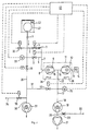
- the figure shows schematically a leak detector, the inlet is denoted by 1.
- the inlet 1 is parallel to the mutually guided line sections 2 (with choke 3 and Valve 4) and 5 (with valve 6) and line 7 with the Entry side 8 of a high vacuum pump stage 9 connected.
- the high vacuum pump stage 9 is a stage of a friction vacuum pump, expediently a two-stage turbomolecular pump 11, the second stage is designated by 12.
- a Test gas detector preferably a mass spectrometer 14 connected to the entry page 13 of the second stage 12 .
- the two exit sides 15 and 16 of the High vacuum pump stages 9 and 12 are common across the Line 17 with the inlet side 18 of a friction pump 19, preferably a turbomolecular pump.
- On the pressure side is to the turbomolecular pump 19 via the connecting line 20 a diaphragm pump 21 connected against Atmospheric pressure works.
- To the Line 17 is also connected to the pressure measuring point 25.
- the two turbomolecular pump stages 9 and 12 are on one arranged common shaft. Ports B and 13 are located in the area of the outer end faces of the turbomolecular pump 11.
- the two pump stages 9 and 12 are from outside to inside during operation (arrows 26) flows through, so that only a backing connection 27 is available is.
- the inlet 1 of the leak detector is also on the Line 28 with the valve 29 with the inlet side 30 one second vacuum pump 31 connected. With this pump 31 it is a working on the spiral principle Vacuum pump. On line 28 are also that Ventilation valve 32 and the pressure measuring point 33 connected. Is between the valve 29 and inlet 30 of the vacuum pump 31 the line 28 finally with a purge gas supply line 34 with the valve 35 in connection.
- the inlet sides 18 and 30 of the two vacuum pumps 19 and 31 are connected to one another via line 37. This is equipped with a control valve 40.
- central controller 41 To automate the leak detection process is one central controller 41 is provided, which in detail Control lines not provided with reference symbols below with the control valves as well as with the pressure measuring points are connected.
- the procedure is as follows: First, when the valves 4, 6, 29, 35, 40 are closed, the leak detector is brought into its operational state by first switching on the vacuum pumps 19, 20 and 31 and then the turbomolecular pump 11 become. The device is ready for operation when the pressure in the mass spectrometer 14 is less than 10 -4 mbar or when the speed of the turbomolecular pump 11 has reached its setpoint and when the backing pressure (measuring device 25) is less than the maximum permissible pressure (e.g. 0.1 mbar).
- test object to be examined 42 which is in the test chamber 43 is located at the inlet 1 of the leak detector connected.
- test gas in the test chamber 43 preferably helium, which is present during the leak detection in the Test object penetrates if it is leaking.
- test gas in the test chamber 43 preferably helium, which is present during the leak detection in the Test object penetrates if it is leaking.
- To the test chamber 43 can be omitted if the device under test 42 Helium is sprayed.
- DUT 42 itself filled with helium. In this case chamber 43 is connected to inlet 1.
- the pressure inside the test piece will drop relatively quickly. If it has reached a value of approximately 100 mbar, the valve 4 is opened, so that the high vacuum pump stage 9 is connected via the throttle 3 to the line 28 or to the inlet 1 and thus to the test object 42. If, during the further evacuation to a pressure of approximately 0.1 mbar helium, the test specimen 42 penetrates, this then reaches the mass spectrometer 14 via the throttle 3 and the two high vacuum pump stages 9 and 12. The leak detection can be stopped in this case. Leaks with leak rates in the order of about 10 to 10 -5 mbar l / s can be detected during this leak detection phase.
- a further leak search with an even higher sensitivity begins, in that the connection to the high vacuum pump stage 9 is released without restriction.
- the valve 29 is closed and the valves 6 and 40 are opened at a pressure of approximately 0.1 mbar in the test specimen 42.
- the test specimen is evacuated via the high-vacuum pump stage 9 and all pumps 19, 21 and 31.
- Any helium that is also conveyed passes through the turbomolecular pump stage 12 to the mass spectrometer 14.
- test object If the test object is still tight, its internal pressure will continue to decrease. If the pressure drops to about 2.10 -2 mbar (measuring device 33), an even more sensitive leak detection phase can be started by closing the valve 40. As a result, the pumping speed of the backing pump system drops sharply, making leak detection correspondingly more sensitive. If helium is not registered by the mass spectrometer 14 in this phase as well, the test specimen 42 can be designated as tight.
- the vacuum pump 21 is a diaphragm pump.
- a turbomolecular pump 19 can be connected upstream of it.
- the pumping speed of the turbomolecular pump is throttled so that a high detection sensitivity can be achieved.
- the problem of the helium background and to solve the bad response time is a constant Gas flow via throttle 23 (e.g. 50 orifice) into the Intermediate line 20 inserted. This tears into the intermediate line 20 incoming helium atoms constantly, so that an unwanted helium background cannot build up.
- valve 35 In order to degrade the helium background in the spiral pump 31, relatively much gas can be pumped. Therefore, when open Valve 35 the pressure so high that a measuring operation at the same time not possible. Therefore, the valve 35 is only then opens automatically when at least the valves 29,39,40 or all valves - except valve 35 - are closed are.
Landscapes
- Physics & Mathematics (AREA)
- General Physics & Mathematics (AREA)
- Examining Or Testing Airtightness (AREA)
- Non-Positive Displacement Air Blowers (AREA)
Abstract
Description
Claims (12)
- Lecksuchgerät mit einer als Reibungsvakuumpumpe (11) ausgebildeten Hochvakuumpumpe und zwei weiteren gegen den Atmosphärendruck arbeitenden Vakuumpumpen (21, 31), dadurch gekennzeichnet, daß beide weiteren Vakuumpumpen (21, 31) trocken verdichtende Vakuumpumpen sind.
- Lecksuchgerät nach Anspruch 1, dadurch gekennzeichnet, daß die trocken verdichtenden Vakuumpumpen Spiralpumpen (31) und/oder Membranpumpen (21) sind.
- Lecksuchgerät nach Anspruch 1 oder 2, dadurch gekennzeichnet, daß die erste der beiden trocken verdichtenden Vakuumpumpen (21, 31), welche mit dem Vorvakuumanschluß (27) der Reibungsvakuumpumpe (11) in Verbindung steht, als Membranpumpe (21) ausgebildet ist.
- Lecksuchgerät nach Anspruch 3, dadurch gekennzeichnet, daß sich zwischen der Membranpumpe (21) und der Reibungsvakuumpumpe (11) eine Turbomolekularpumpe (19) befindet.
- Lecksuchgerät nach Anspruch 4, dadurch gekennzeichnet, daß das Saugvermögen der Turbomolekularpumpe (19) zur Verbesserung der Nachweisempfindlichkeit gedrosselt ist.
- Lecksuchgerät nach Anspruch 3, 4 oder 5, dadurch gekennzeichnet, daß im Bereich des Einlaßes der Membranpumpe (21) eine Spülgaszuführungsleitung (22) mündet.
- Lecksuchgerät nach Anspruch 6, dadurch gekennzeichnet, daß sich in der Spülgaszuführungsleitung (22) eine Drossel (23) befindet.
- Lecksuchgerät nach einem der Ansprüche 1 bis 7, dadurch gekennzeichnet, daß die zweite der beiden trocken verdichtenden Vakuumpumpen (21, 31), welche über eine Leitung (23) mit dem Ventil (24) unmittelbar mit dem Einlaß des Lecksuchgerätes (1) in Verbindung steht, als Spiralpumpe (31) ausgebildet ist.
- Lecksuchgerät nach Anspruch 8, dadurch gekennzeichnet, im Bereich des Einlasses der Spiralpumpe (31) eine Spülgaszuführungsleitung mündet.
- Lecksuchgerät nach Anspruch 4 und Anspruch 8 oder 9, dadurch gekennzeichnet, dass die Eintrittsseiten (18, 30) der beiden Vakuumpumpen (19, 31) über eine Leitung (37) miteinander verbunden sind, die mit einem Ventil (40) ausgerüstet ist.
- Verfahren zum Betrieb eines Lecksuchgerätes mit einer als Reibungsvakuumpumpe (11) ausgebildeten Hochvakuumpumpe und zwei weiteren gegen den Atmosphärendruck arbeitenden trocken verdichtenden Vakuumpumpen (21, 31), wobeidiejenige der beiden trocken verdichtenden Vakuum pumpen (21, 31), welche mit dem Vorvakuumanschluß (27) der Reibungsvakuumpumpe (11) in Verbindung steht, als Membranpumpe (21) ausgebildet ist undim Bereich des Einlasses der Membranpumpe (21) eine Spülgaszuführungsleitung (22) mit einer Drossel (23) mündet,dadurch gekennzeichnet,dass während der Durchführung der Lecksuchmessungen über die Spülgaszuführungsleitung (22) mit der Drossel (23) ständig ein Gasstrom eingelassen wird.
- Verfahren zum Betrieb eines Lecksuchgerätes mit einer als Reibungsvakuumpumpe (11) ausgebildeten Hochvakuumpumpe und zwei weiteren gegen den Atmosphärendruck arbeitenden trocken verdichtenden Vakuumpumpen (21, 31), wobeidadurch gekennzeichnet,diejenige der beiden trocken verdichtenden Vakuumpumpen (21, 31), welche mit dem Vorvakuumanschluß (27) der Reibungsvakuumpumpe (11) in Verbindung steht, als Membranpumpe (21) ausgebildet ist,zwischen der Membranpumpe (21) und der Reibungsvakuumpumpe (11) eine Turbomolekularpumpe (19) angeordnet ist,die Eintrittsseiten (18, 30) der beiden Vakuumpumpen (19, 31) über eine Leitung (37) miteinander verbunden sind, die mit einem ersten Ventil (40) ausgerüstet ist,die zweite der beiden trocken verdichtenden Vakuumpumpen (21, 31), welche über eine Leitung (28) mit einem zweiten Ventil (29) unmittelbar mit dem Einlaß des Lecksuchgerätes (1) in Verbindung steht, als Spiralpumpe (31) ausgebildet ist undim Bereich des Einlasses der Spiralpumpe (31) eine Spülgaszuführungsleitung (34) mit einem dritten Ventil (35) mündet,dass über die Spülgaszuführungsleitung (34) mit dem dritten Ventil (35) nur dann Spülgas eingelassen wird, wenn mindestens das erste und zweite Ventil (29, 40) geschlossen sind.
Applications Claiming Priority (3)
| Application Number | Priority Date | Filing Date | Title |
|---|---|---|---|
| DE4442174 | 1994-11-26 | ||
| DE4442174A DE4442174A1 (de) | 1994-11-26 | 1994-11-26 | Lecksuchgerät mit Vakuumpumpen und Betriebsverfahren dazu |
| PCT/EP1995/003960 WO1996017237A1 (de) | 1994-11-26 | 1995-10-07 | Lecksuchgerät mit vakuumpumpen und betriebsverfahren dazu |
Publications (2)
| Publication Number | Publication Date |
|---|---|
| EP0793802A1 EP0793802A1 (de) | 1997-09-10 |
| EP0793802B1 true EP0793802B1 (de) | 2002-04-10 |
Family
ID=6534258
Family Applications (1)
| Application Number | Title | Priority Date | Filing Date |
|---|---|---|---|
| EP95936454A Expired - Lifetime EP0793802B1 (de) | 1994-11-26 | 1995-10-07 | Lecksuchgerät mit vakuumpumpen und betriebsverfahren dazu |
Country Status (6)
| Country | Link |
|---|---|
| US (1) | US5880357A (de) |
| EP (1) | EP0793802B1 (de) |
| JP (1) | JP3568536B2 (de) |
| CN (1) | CN1088516C (de) |
| DE (2) | DE4442174A1 (de) |
| WO (1) | WO1996017237A1 (de) |
Families Citing this family (25)
| Publication number | Priority date | Publication date | Assignee | Title |
|---|---|---|---|---|
| DE19709206A1 (de) * | 1997-03-06 | 1998-09-10 | Leybold Vakuum Gmbh | Vakuumpumpe |
| FR2761776B1 (fr) * | 1997-04-03 | 1999-07-23 | Alsthom Cge Alcatel | Detecteur de fuite a gaz traceur |
| DE19831123A1 (de) * | 1998-07-11 | 2000-01-13 | Pfeiffer Vacuum Gmbh | Gasballasteinrichtung für mehrstufige Verdrängerpumpen |
| DE10156205A1 (de) * | 2001-11-15 | 2003-06-05 | Inficon Gmbh | Testgaslecksuchgerät |
| US7033142B2 (en) * | 2003-01-24 | 2006-04-25 | Pfeifer Vacuum Gmbh | Vacuum pump system for light gases |
| DE10324596A1 (de) * | 2003-05-30 | 2004-12-16 | Inficon Gmbh | Lecksuchgerät |
| US20070028669A1 (en) * | 2003-09-26 | 2007-02-08 | Brewster Barrie D | Detection of contaminants within fluid pumped by a vacuum pump |
| DE102005054638B4 (de) * | 2005-11-16 | 2013-09-26 | Oerlikon Leybold Vacuum Gmbh | Mobiles Lecksuchegerät |
| EP2517001A4 (de) * | 2009-12-22 | 2014-08-20 | Ima Life North America Inc | Überwachung von gefriertrocknung mit gasmessung am vakuumpumpenauslass |
| DE102010033373A1 (de) * | 2010-08-04 | 2012-02-09 | Inficon Gmbh | Lecksuchgerät |
| DE102010055798A1 (de) * | 2010-08-26 | 2012-03-01 | Vacuubrand Gmbh + Co Kg | Vakuumpumpe |
| JP5948349B2 (ja) * | 2011-02-03 | 2016-07-06 | オーリコン レイボルド バキューム ゲーエムベーハー | 漏れ検出デバイス |
| FR2974412B1 (fr) * | 2011-04-21 | 2013-06-07 | Adixen Vacuum Products | Procede de controle d'un detecteur de fuites et detecteur de fuites |
| CN103071358A (zh) * | 2012-12-27 | 2013-05-01 | 博益(天津)气动技术研究所有限公司 | 一种用于微小泄漏检测的氢气过滤器 |
| CN104142216A (zh) * | 2014-08-04 | 2014-11-12 | 无锡日联科技有限公司 | 新型真空微漏检测方法 |
| CN104198131B (zh) * | 2014-09-04 | 2017-04-12 | 安徽华东光电技术研究所 | 行波管检漏设备在行波管检漏中的应用方法 |
| CN106989915B (zh) * | 2017-05-31 | 2020-02-11 | 西南石油大学 | 一种垂直式高速牙轮钻头轴承螺旋密封试验装置 |
| CN106989874B (zh) * | 2017-05-31 | 2020-02-07 | 西南石油大学 | 一种水平式高速牙轮钻头轴承螺旋密封试验装置 |
| FR3070489B1 (fr) * | 2017-08-29 | 2020-10-23 | Pfeiffer Vacuum | Detecteur de fuites et procede de detection de fuites pour le controle de l'etancheite d'objets a tester |
| FR3072774B1 (fr) * | 2017-10-19 | 2019-11-15 | Pfeiffer Vacuum | Detecteur de fuites pour le controle de l'etancheite d'un objet a tester |
| DE102020132896A1 (de) * | 2020-12-10 | 2022-06-15 | Inficon Gmbh | Vorrichtung zur massenspektrometrischen Leckdetektion mit dreistufiger Turbomolekularpumpe und Boosterpumpe |
| CN113063547B (zh) * | 2021-03-22 | 2021-12-07 | 攀钢集团攀枝花钢钒有限公司 | Rh炉真空系统泄漏查找方法 |
| DE102021115664A1 (de) * | 2021-06-17 | 2022-12-22 | Inficon Gmbh | Leckdetektoren |
| DE102021119256A1 (de) * | 2021-07-26 | 2023-01-26 | Inficon Gmbh | Leckdetektoren |
| CN117168712B (zh) * | 2023-11-03 | 2024-04-02 | 宁德时代新能源科技股份有限公司 | 检测组件、检测设备及其检测方法 |
Family Cites Families (9)
| Publication number | Priority date | Publication date | Assignee | Title |
|---|---|---|---|---|
| DE2831179A1 (de) * | 1978-07-15 | 1980-01-24 | Leybold Heraeus Gmbh & Co Kg | Verdraengermaschine nach dem spiralprinzip |
| DE3775213D1 (de) * | 1987-03-27 | 1992-01-23 | Leybold Ag | Lecksuchgeraet und betriebsverfahren dazu. |
| DE3710782A1 (de) * | 1987-03-31 | 1988-10-20 | Vacuubrand Gmbh & Co | Verfahren und vorrichtung zum abpumpen von daempfen und/oder dampfhaltigen gemischen und/oder gas-dampf-gemischen oder dgl. medien |
| US4893497A (en) * | 1988-09-12 | 1990-01-16 | Philip Danielson | Leak detection system |
| FR2653558B1 (fr) * | 1989-10-23 | 1994-06-10 | Cit Alcatel | Systeme de detection de fuites a gaz traceur. |
| FR2681688B1 (fr) * | 1991-09-24 | 1993-11-19 | Alcatel Cit | Installation de detection de fuites de gaz utilisant la technique de reniflage. |
| FR2681689B1 (fr) * | 1991-09-25 | 1993-11-12 | Alcatel Cit | Detecteur de fuite a gaz traceur. |
| DE4136950A1 (de) * | 1991-11-11 | 1993-05-13 | Pfeiffer Vakuumtechnik | Mehrstufiges vakuumpumpsystem |
| DE9305554U1 (de) * | 1993-04-15 | 1993-06-17 | KNF-Neuberger GmbH, 7800 Freiburg | Zweifach-Verdrängerpumpe |
-
1994
- 1994-11-26 DE DE4442174A patent/DE4442174A1/de not_active Withdrawn
-
1995
- 1995-10-07 US US08/836,921 patent/US5880357A/en not_active Expired - Fee Related
- 1995-10-07 DE DE59510160T patent/DE59510160D1/de not_active Expired - Lifetime
- 1995-10-07 WO PCT/EP1995/003960 patent/WO1996017237A1/de not_active Ceased
- 1995-10-07 JP JP51810696A patent/JP3568536B2/ja not_active Expired - Fee Related
- 1995-10-07 EP EP95936454A patent/EP0793802B1/de not_active Expired - Lifetime
- 1995-11-24 CN CN95120249A patent/CN1088516C/zh not_active Expired - Fee Related
Also Published As
| Publication number | Publication date |
|---|---|
| CN1132855A (zh) | 1996-10-09 |
| CN1088516C (zh) | 2002-07-31 |
| EP0793802A1 (de) | 1997-09-10 |
| JPH10510050A (ja) | 1998-09-29 |
| DE59510160D1 (de) | 2002-05-16 |
| JP3568536B2 (ja) | 2004-09-22 |
| US5880357A (en) | 1999-03-09 |
| WO1996017237A1 (de) | 1996-06-06 |
| DE4442174A1 (de) | 1996-05-30 |
Similar Documents
| Publication | Publication Date | Title |
|---|---|---|
| EP0793802B1 (de) | Lecksuchgerät mit vakuumpumpen und betriebsverfahren dazu | |
| EP0283543B1 (de) | Lecksuchgerät und Betriebsverfahren dazu | |
| EP0344345B1 (de) | Pumpsystem für ein Lecksuchgerät | |
| EP0615615B1 (de) | Lecksucher für vakuumanlagen sowie verfahren zur durchführung der lecksuche an vakuumanlagen | |
| EP2601498B1 (de) | Lecksuchgerät | |
| DE1648648C3 (de) | Anordnung zur Lecksuche nach dem Massenspektrometer-Prinzip | |
| EP1620706B1 (de) | Lecksuchgerät | |
| DE19523430C2 (de) | Lecknachweisgerät, das eine Verbund-Turbomolekularpumpe benutzt | |
| EP0805962B1 (de) | Testgas Lecksuche mit einer Leitwertregelung nach Vorvakuumdruck oder Zwischenanschlussdruck | |
| DE1937271B2 (de) | Anordnung zur Lecksuche | |
| EP0242684B1 (de) | Lecksuchgerät mit Detektor und Testleck | |
| EP0657025A1 (de) | Gegenstrom-lecksucher mit hochvakuumpumpe. | |
| WO2003042651A1 (de) | Testgaslecksuchgerät | |
| EP0834061B1 (de) | Lecksuchgerät mit vorvakuumpumpe | |
| EP4185851B1 (de) | Vakuumlecksuchsystem, gassteuereinheit und verfahren zur gaslecksuche | |
| DE10055057A1 (de) | Leckdetektorpumpe | |
| DE69007930T2 (de) | System zur Aufspürung von Undichtigkeit unter Verwendung von Trägergas. | |
| DE10324596A1 (de) | Lecksuchgerät | |
| EP0718613B1 (de) | Verfahren zur Gasanalyse und Gasanalysator | |
| EP0752095B1 (de) | Testgas-lecksuchgerät | |
| WO2024099639A1 (de) | Trägergas-lecksuchsystem und trägergas-lecksuchverfahren zur leckagedetektion an einem prüfling |
Legal Events
| Date | Code | Title | Description |
|---|---|---|---|
| PUAI | Public reference made under article 153(3) epc to a published international application that has entered the european phase |
Free format text: ORIGINAL CODE: 0009012 |
|
| 17P | Request for examination filed |
Effective date: 19970228 |
|
| AK | Designated contracting states |
Kind code of ref document: A1 Designated state(s): CH DE FR GB IT LI |
|
| 17Q | First examination report despatched |
Effective date: 19990730 |
|
| GRAG | Despatch of communication of intention to grant |
Free format text: ORIGINAL CODE: EPIDOS AGRA |
|
| GRAG | Despatch of communication of intention to grant |
Free format text: ORIGINAL CODE: EPIDOS AGRA |
|
| GRAH | Despatch of communication of intention to grant a patent |
Free format text: ORIGINAL CODE: EPIDOS IGRA |
|
| GRAH | Despatch of communication of intention to grant a patent |
Free format text: ORIGINAL CODE: EPIDOS IGRA |
|
| REG | Reference to a national code |
Ref country code: GB Ref legal event code: IF02 |
|
| GRAA | (expected) grant |
Free format text: ORIGINAL CODE: 0009210 |
|
| AK | Designated contracting states |
Kind code of ref document: B1 Designated state(s): CH DE FR GB IT LI |
|
| REG | Reference to a national code |
Ref country code: CH Ref legal event code: EP |
|
| REF | Corresponds to: |
Ref document number: 59510160 Country of ref document: DE Date of ref document: 20020516 |
|
| REG | Reference to a national code |
Ref country code: CH Ref legal event code: NV Representative=s name: ISLER & PEDRAZZINI AG |
|
| GBT | Gb: translation of ep patent filed (gb section 77(6)(a)/1977) |
Effective date: 20020704 |
|
| ET | Fr: translation filed | ||
| PLBE | No opposition filed within time limit |
Free format text: ORIGINAL CODE: 0009261 |
|
| STAA | Information on the status of an ep patent application or granted ep patent |
Free format text: STATUS: NO OPPOSITION FILED WITHIN TIME LIMIT |
|
| 26N | No opposition filed |
Effective date: 20030113 |
|
| REG | Reference to a national code |
Ref country code: CH Ref legal event code: PCAR Free format text: ISLER & PEDRAZZINI AG;POSTFACH 1772;8027 ZUERICH (CH) |
|
| PGFP | Annual fee paid to national office [announced via postgrant information from national office to epo] |
Ref country code: DE Payment date: 20091026 Year of fee payment: 15 Ref country code: CH Payment date: 20091026 Year of fee payment: 15 |
|
| PGFP | Annual fee paid to national office [announced via postgrant information from national office to epo] |
Ref country code: IT Payment date: 20091029 Year of fee payment: 15 Ref country code: GB Payment date: 20091022 Year of fee payment: 15 Ref country code: FR Payment date: 20091110 Year of fee payment: 15 |
|
| REG | Reference to a national code |
Ref country code: CH Ref legal event code: PL |
|
| GBPC | Gb: european patent ceased through non-payment of renewal fee |
Effective date: 20101007 |
|
| PG25 | Lapsed in a contracting state [announced via postgrant information from national office to epo] |
Ref country code: CH Free format text: LAPSE BECAUSE OF NON-PAYMENT OF DUE FEES Effective date: 20101031 Ref country code: FR Free format text: LAPSE BECAUSE OF NON-PAYMENT OF DUE FEES Effective date: 20101102 Ref country code: LI Free format text: LAPSE BECAUSE OF NON-PAYMENT OF DUE FEES Effective date: 20101031 |
|
| REG | Reference to a national code |
Ref country code: FR Ref legal event code: ST Effective date: 20110630 |
|
| REG | Reference to a national code |
Ref country code: DE Ref legal event code: R119 Ref document number: 59510160 Country of ref document: DE Effective date: 20110502 |
|
| PG25 | Lapsed in a contracting state [announced via postgrant information from national office to epo] |
Ref country code: GB Free format text: LAPSE BECAUSE OF NON-PAYMENT OF DUE FEES Effective date: 20101007 |
|
| PG25 | Lapsed in a contracting state [announced via postgrant information from national office to epo] |
Ref country code: IT Free format text: LAPSE BECAUSE OF NON-PAYMENT OF DUE FEES Effective date: 20101007 |
|
| PG25 | Lapsed in a contracting state [announced via postgrant information from national office to epo] |
Ref country code: DE Free format text: LAPSE BECAUSE OF NON-PAYMENT OF DUE FEES Effective date: 20110502 |