EP0793769B1 - Variabler ventilhebemechanismus für brennkraftmaschine - Google Patents
Variabler ventilhebemechanismus für brennkraftmaschine Download PDFInfo
- Publication number
- EP0793769B1 EP0793769B1 EP95940781A EP95940781A EP0793769B1 EP 0793769 B1 EP0793769 B1 EP 0793769B1 EP 95940781 A EP95940781 A EP 95940781A EP 95940781 A EP95940781 A EP 95940781A EP 0793769 B1 EP0793769 B1 EP 0793769B1
- Authority
- EP
- European Patent Office
- Prior art keywords
- toothed
- rocker arm
- pivot shaft
- valve
- cog
- Prior art date
- Legal status (The legal status is an assumption and is not a legal conclusion. Google has not performed a legal analysis and makes no representation as to the accuracy of the status listed.)
- Expired - Lifetime
Links
- 238000002485 combustion reaction Methods 0.000 title claims description 5
- 101100114358 Neurospora crassa (strain ATCC 24698 / 74-OR23-1A / CBS 708.71 / DSM 1257 / FGSC 987) cog-6 gene Proteins 0.000 description 4
- 238000000034 method Methods 0.000 description 3
- 239000011295 pitch Substances 0.000 description 3
- 230000009849 deactivation Effects 0.000 description 2
- 230000010363 phase shift Effects 0.000 description 2
- 239000011435 rock Substances 0.000 description 2
- 235000011449 Rosa Nutrition 0.000 description 1
- 230000003321 amplification Effects 0.000 description 1
- 230000000052 comparative effect Effects 0.000 description 1
- 230000009977 dual effect Effects 0.000 description 1
- 230000000694 effects Effects 0.000 description 1
- 239000000446 fuel Substances 0.000 description 1
- 238000003199 nucleic acid amplification method Methods 0.000 description 1
Images



Classifications
-
- F—MECHANICAL ENGINEERING; LIGHTING; HEATING; WEAPONS; BLASTING
- F02—COMBUSTION ENGINES; HOT-GAS OR COMBUSTION-PRODUCT ENGINE PLANTS
- F02B—INTERNAL-COMBUSTION PISTON ENGINES; COMBUSTION ENGINES IN GENERAL
- F02B41/00—Engines characterised by special means for improving conversion of heat or pressure energy into mechanical power
- F02B41/02—Engines with prolonged expansion
- F02B41/04—Engines with prolonged expansion in main cylinders
-
- F—MECHANICAL ENGINEERING; LIGHTING; HEATING; WEAPONS; BLASTING
- F01—MACHINES OR ENGINES IN GENERAL; ENGINE PLANTS IN GENERAL; STEAM ENGINES
- F01L—CYCLICALLY OPERATING VALVES FOR MACHINES OR ENGINES
- F01L13/00—Modifications of valve-gear to facilitate reversing, braking, starting, changing compression ratio, or other specific operations
- F01L13/0015—Modifications of valve-gear to facilitate reversing, braking, starting, changing compression ratio, or other specific operations for optimising engine performances by modifying valve lift according to various working parameters, e.g. rotational speed, load, torque
- F01L13/0021—Modifications of valve-gear to facilitate reversing, braking, starting, changing compression ratio, or other specific operations for optimising engine performances by modifying valve lift according to various working parameters, e.g. rotational speed, load, torque by modification of rocker arm ratio
-
- F—MECHANICAL ENGINEERING; LIGHTING; HEATING; WEAPONS; BLASTING
- F02—COMBUSTION ENGINES; HOT-GAS OR COMBUSTION-PRODUCT ENGINE PLANTS
- F02D—CONTROLLING COMBUSTION ENGINES
- F02D13/00—Controlling the engine output power by varying inlet or exhaust valve operating characteristics, e.g. timing
- F02D13/02—Controlling the engine output power by varying inlet or exhaust valve operating characteristics, e.g. timing during engine operation
- F02D13/0223—Variable control of the intake valves only
- F02D13/0226—Variable control of the intake valves only changing valve lift or valve lift and timing
-
- F—MECHANICAL ENGINEERING; LIGHTING; HEATING; WEAPONS; BLASTING
- F02—COMBUSTION ENGINES; HOT-GAS OR COMBUSTION-PRODUCT ENGINE PLANTS
- F02D—CONTROLLING COMBUSTION ENGINES
- F02D15/00—Varying compression ratio
- F02D15/04—Varying compression ratio by alteration of volume of compression space without changing piston stroke
-
- F—MECHANICAL ENGINEERING; LIGHTING; HEATING; WEAPONS; BLASTING
- F02—COMBUSTION ENGINES; HOT-GAS OR COMBUSTION-PRODUCT ENGINE PLANTS
- F02F—CYLINDERS, PISTONS OR CASINGS, FOR COMBUSTION ENGINES; ARRANGEMENTS OF SEALINGS IN COMBUSTION ENGINES
- F02F1/00—Cylinders; Cylinder heads
- F02F1/24—Cylinder heads
- F02F1/42—Shape or arrangement of intake or exhaust channels in cylinder heads
- F02F1/4214—Shape or arrangement of intake or exhaust channels in cylinder heads specially adapted for four or more valves per cylinder
-
- F—MECHANICAL ENGINEERING; LIGHTING; HEATING; WEAPONS; BLASTING
- F02—COMBUSTION ENGINES; HOT-GAS OR COMBUSTION-PRODUCT ENGINE PLANTS
- F02B—INTERNAL-COMBUSTION PISTON ENGINES; COMBUSTION ENGINES IN GENERAL
- F02B1/00—Engines characterised by fuel-air mixture compression
- F02B1/02—Engines characterised by fuel-air mixture compression with positive ignition
- F02B1/04—Engines characterised by fuel-air mixture compression with positive ignition with fuel-air mixture admission into cylinder
-
- F—MECHANICAL ENGINEERING; LIGHTING; HEATING; WEAPONS; BLASTING
- F02—COMBUSTION ENGINES; HOT-GAS OR COMBUSTION-PRODUCT ENGINE PLANTS
- F02B—INTERNAL-COMBUSTION PISTON ENGINES; COMBUSTION ENGINES IN GENERAL
- F02B75/00—Other engines
- F02B75/02—Engines characterised by their cycles, e.g. six-stroke
- F02B2075/022—Engines characterised by their cycles, e.g. six-stroke having less than six strokes per cycle
- F02B2075/025—Engines characterised by their cycles, e.g. six-stroke having less than six strokes per cycle two
-
- F—MECHANICAL ENGINEERING; LIGHTING; HEATING; WEAPONS; BLASTING
- F02—COMBUSTION ENGINES; HOT-GAS OR COMBUSTION-PRODUCT ENGINE PLANTS
- F02B—INTERNAL-COMBUSTION PISTON ENGINES; COMBUSTION ENGINES IN GENERAL
- F02B2275/00—Other engines, components or details, not provided for in other groups of this subclass
- F02B2275/18—DOHC [Double overhead camshaft]
-
- F—MECHANICAL ENGINEERING; LIGHTING; HEATING; WEAPONS; BLASTING
- F02—COMBUSTION ENGINES; HOT-GAS OR COMBUSTION-PRODUCT ENGINE PLANTS
- F02B—INTERNAL-COMBUSTION PISTON ENGINES; COMBUSTION ENGINES IN GENERAL
- F02B3/00—Engines characterised by air compression and subsequent fuel addition
- F02B3/06—Engines characterised by air compression and subsequent fuel addition with compression ignition
-
- Y—GENERAL TAGGING OF NEW TECHNOLOGICAL DEVELOPMENTS; GENERAL TAGGING OF CROSS-SECTIONAL TECHNOLOGIES SPANNING OVER SEVERAL SECTIONS OF THE IPC; TECHNICAL SUBJECTS COVERED BY FORMER USPC CROSS-REFERENCE ART COLLECTIONS [XRACs] AND DIGESTS
- Y02—TECHNOLOGIES OR APPLICATIONS FOR MITIGATION OR ADAPTATION AGAINST CLIMATE CHANGE
- Y02T—CLIMATE CHANGE MITIGATION TECHNOLOGIES RELATED TO TRANSPORTATION
- Y02T10/00—Road transport of goods or passengers
- Y02T10/10—Internal combustion engine [ICE] based vehicles
- Y02T10/12—Improving ICE efficiencies
Definitions
- This invention relates to an apparatus for simultaneously varying the phase and extent of opening of a valve of an internal combustion engine.
- phase has been accomplished in a number of different ways.
- One of the simplest methods to comprehend is to alter the phase between the crankshaft and the intake camshaft in a dual overhead camshaft layout. This may occur with a drive mechanism that incorporates splines on the camshaft and a driving drum, a shown in SAE paper 901727. During operation the driving drum and camshaft are moved relative to each other while the cam drive undergoes normal operation.
- a more complicated means of achieving phase variation is to use a three dimensional cam that is moved axially.
- This type of system as described in US-A-3,618,574 by Miller and US-A-5,080,055 by Komatsu, et al., can be used to vary lift, duration and phase in a variety of ways.
- phase may be altered in a step-wise fashion from one angle to a second angle.
- Such a mechanism also allows the possibility of a step variation of lift and duration.
- FR-A-2 566 838 discloses a method for operating and varying the extent of opening of a valve responsive to a cam on a camshaft by simultaneously changing the lever ratio of a rocker arm and displacing its line of contact with the operating cam along the cam profile.
- the present invention extends the system for dynamically altering the lift and duration of a valve in an internal combustion engine, as described in earlier applications, to include variable phase.
- an apparatus for simultaneously varying the phase and extent of opening of a valve of an internal combustion engine comprising a rotatable camshaft having a cam thereon; a valve; a rocker arm having a first end actuable by said cam and a second end engagable with said valve; and a pivot shaft on which the rocker arm is pivotally engaged; characterised by the pivot shaft having a first toothed cog with a first diameter engaged with the rocker-arm and a second toothed cog with a second diameter different from said first diameter engaged with a stationary rack, the arrangement being such that, in use, rotation of the pivot shaft results in (a) movement of the pivot shaft along the stationary rack and the rocker arm, and (b) movement of the rocker arm in relation to the stationary rack and the camshaft to simultaneously vary the phase and extent of opening of the valve.
- movement of the pivot shaft along the stationary rack simultaneously varies the duration of the valve opening.
- the rocker arm includes a toothed rack engaged with the first toothed cog.
- the pivot shaft further includes a third toothed cog and a second stationary rack, the third toothed cog being engaged with said second stationary rack, the second toothed cog and third toothed cog being of the same diameter as one another, the first toothed cog being on the pivot shaft between the second toothed cog and the third toothed cog, and the toothed rack on the rocker arm being between said two stationary toothed racks.
- said apparatus further comprises caps and a set of bearings to engage the pivot shaft with the caps.
- the caps include a surface substantially perpendicular to the longitudinal axis of the pivot shaft and on a side of the pivot shaft opposite the toothed rack on the rocker arm along which the pivot shaft travels as it rolls along the toothed racks.
- Variations in phase are achieved by displacing the rocker arm by small amounts in a lengthwise direction. As the pivot shaft moves from one position to another, the rocker arm will move either a smaller or a larger distance, depending on the changes desired.
- the degree of lift of the valves may be altered, along with the duration the valve is open, and the phase with which the valve is opened, to optimise engine torque at different engine speeds, as well as to improve idle stability and fuel efficiency.
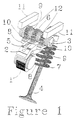
- FIG. 1 shows the mechanism assembled
- FIG. 2 shows the mechanism in exploded format.
- cam 1 rocks rocker arm 2 against pivot shaft 3 to open valve 4.
- toothed rack 5 on the upper surface of said rocker arm 2 is held in mesh with the teeth of toothed cog 6 on pivot shaft 3 by a light spring (not shown).
- a light spring not shown
- the resistive force of the valve spring 7 associated with valve 4 ensures contact between the toothed rack 5 and the toothed pivot cog 6.
- Stationary rack 8 is shown as having the same straight line shape and tooth pitch as toothed rack 5 on the upper surface of rocker arm 2.
- Toothed cog 9 on pivot shaft 3 has the same diameter and tooth pitch as toothed cog 6 in FIG.1.
- pivot shaft 3 When pivot shaft 3 is located at any one particular position it is prevented from rotating by stationary rack 8.
- the equal pitches and diameters of toothed cogs 6 and 9, and toothed racks 5 and 8 in FIG. 1 ensure that the rocker arm 2 does not move parallel to its length.
- Bearing 10 allows pivot shaft 3 to roll over the lower surfaces of caps 11, which not only constrain the upward force of the cam and valve, but provide appropriate clearance variation, if desired, between maximum and minimum lift.
- the shape of the underside of caps 11 is shown as straight here, although it may be curved.
- the annular, non-toothed surfaces 12 on pivot shaft 3 ride on flat surfaces 13 of rocker arm 2 (see FIG.2) in this case. Surfaces 13 may be curved also.
- toothed rack 5 may float in rocker arm 2 the same way that stationary rack 8 may float. Either or both springs or hydraulic pressure may be used to urge the toothed racks upwards.
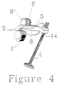
- FIGS. 3 and 4 many components have been removed to highlight the effects of altering the diameters of the toothed cogs 6 and 9 on pivot shaft 3.
- FIG. 3 shows toothed cogs 6 and 9 to be the same diameter.
- Stationary rack 8 is at the same height as toothed rack 5 on rocker arm 2.
- toothed cogs 6 and 9 traverse toothed racks 5 and 8 in unison, with no change in phase.
- FIG. 4 shows toothed cogs 6 and 9' to be of different diameters.
- toothed cog 9' has one more tooth than toothed cog 9 in FIG. 3, and to keep the same tooth profile, the diameter of toothed cog 9' is greater than toothed cog 6.
- Stationery rack 8 is lower in height compared to FIG. 3, to allow for the altered distance from the centreline of pivot shaft 3 due to the greater diameter of toothed cog 9'.
- rocker arm 3 will be moved lengthwise. The purpose is to move the contact point of cam 1 with rocker arm 2 in a controllable fashion to alter the phase of the opening and closing of the valve.
- toothed cogs 6 and 9' will depend on the direction of rotation of cam 1 and also the strategy with which the phase is to be altered. With toothed cog 9' being concentric on pivot shaft 3, phase will be altered linearly from one extreme of position of pivot shaft 3 to the other extreme. Toothed cog 9' may be mounted eccentrically on pivot shaft 3, with an appropriately altered shape to the control paths 11, to alter the phase in a non-linear manner. In either case, the size of the tappet 14 will be greater than one in which the phase is not so altered. The geometry of tappet 14 may be different from that shown, but the purpose is to allow the force transmitted through rocker arm 2 to actuate valve 4.
- FIG. 4 shows the rocker arm 2 and toothed cogs 6 and 9' at maximum cam lift, and greatest amplification of the cam lift. This geometry is suitable for high speed operation, where the phase of maximum valve lift will occur later than at lower engine speeds. Tappet 14 is slightly offset from the top of valve 4.
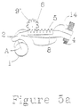
- FIG. 5a shows the contact angle of cam 1 and rocker arm 2 at maximum valve lift. Toothed racks 5 and 8 are aligned at their left ends. Tappet 14 is offset so that it is not squarely over the top of valve 4. Line A shows peak lift of cam 1, and it is in contact with rocker arm 2 here.
- FIG. 5b shows the change in contact angle as pivot shaft 3 is moved to the right and towards minimum valve lift.
- Line B on cam 1 is now in contact with rocker arm 2.
- the variation in crankshaft angle between lines A and B on cam 1 is approximately 10" for this particular case.
- Stationary rack 8 and valve 4 have stayed in their original positions, and rocker arm 2 has moved to the right, due to the difference in diameters of toothed cogs 6 and 9'.
- Valve 4 is now acted upon by tappet 14 on the opposite side to the maximum lift case shown in FIG. 5a. Different diameters for toothed cogs 6 and 9' will yield greater or smaller angular variations.
- the lower lift case would correspond to lower engine speeds, with shorter duration and the phase angle at maximum cam lift would be retarded from the high speed, high lift case, where valve duration would be longer.
- the angle between the line from the pivot point defined by the contact of bearing surfaces 12 and 13 to the top of valve 4 and the axis of valve 4 should not vary too greatly from maximum to minimum lift. As lift is reduced however, this becomes less of a design problem. (Valve deactivation may occur with further movement of the pivot towards the valve, although phase is then irrelevant. Similarly, the angle between the pivot point of pivot shaft 3 and rocker arm 2 to the contact point of the tappet 14 and valve 4, and the axis of valve 4, is not important for valve deactivation. This results in a greater cross sectional area of the rocker arm that may be reinforced to provide suitable structural stiffness.)
Landscapes
- Engineering & Computer Science (AREA)
- Mechanical Engineering (AREA)
- General Engineering & Computer Science (AREA)
- Chemical & Material Sciences (AREA)
- Combustion & Propulsion (AREA)
- Valve Device For Special Equipments (AREA)
- Valve-Gear Or Valve Arrangements (AREA)
Claims (6)
- Vorrichtung zum gleichzeitigen Ändern der Phase und des Ausmaßes der Öffnung eines Ventils einer Brennkraftmaschine, wobei die Vorrichtung eine drehbare Nockenwelle mit einem daran ausgebildeten Nocken (1); ein Ventil (4); einen Kipphebel (2) mit einem ersten Ende, das durch den Nocken (1) betätigbar ist, und einem zweiten Ende, das mit dem Ventil (4) in Eingriff gelangen kann; und einer Schwenkwelle (3), an der der Kipphebel (2) angelenkt ist, umfaßt; dadurch gekennzeichnet, daß die Schwenkwelle (3) ein erstes Zahnrad (6) mit einem ersten Durchmesser, das mit dem Kipphebel (2) in Eingriff ist, und ein zweites Zahnrad (9) mit einem vom ersten Durchmesser verschiedenen zweiten Durchmesser, das mit einer unbeweglichen Zahnstange (8) in Eingriff ist, umfaßt, wobei die Anordnung derart ist, daß die Drehung der Schwenkwelle (3) im Gebrauch (a) eine Bewegung der Schwenkwelle (3) längs der unbeweglichen Zahnstange (8) und des Kipphebels (2) und (b) eine Bewegung des Kipphebels (2) relativ zur unbeweglichen Zahnstange (8) und zur Nockenwelle zur Folge hat, um gleichzeitig die Phase und das Ausmaß der Öffnung des Ventils (4) zu ändern.
- Vorrichtung nach Anspruch 1, bei der die Bewegung der Schwenkwelle (3) längs der unbeweglichen Zahnstange (8) gleichzeitig die Dauer der Öffnung des Ventils (4) ändert.
- Vorrichtung nach Anspruch 1 oder 2, bei der der Kipphebel (2) eine Zahnstange (5) aufweist, die mit dem ersten Zahnrad (6) in Eingriff ist.
- Vorrichtung nach Anspruch 3, bei der die Schwenkwelle (3) ferner ein drittes Zahnrad (9) und eine zweite unbewegliche Zahnstange (8) aufweist, wobei das dritte Zahnrad (9) mit der zweiten unbeweglichen Zahnstange (8) in Eingriff ist, das zweite Zahnrad (9) und das dritte Zahnrad (19) den gleichen Durchmesser besitzen, das erste Zahnrad (6) sich an der Schwenkwelle (3) zwischen dem zweiten Zahnrad (8) und dem dritten Zahnrad 89) befindet und die Zahnstange 85) sich am Kipphebel (2) zwischen den beiden unbeweglichen Zahnstangen (8) befindet.
- Vorrichtung nach Anspruch 4, ferner mit Aufsätzen (11) und einem Satz Auflager (10), um die Schwenkwelle (3) mit den Aufsätzen (11) in Eingriff zu bringen.
- Vorrichtung nach Anspruch 5, bei der die Aufsätze (11) eine zur Längsachse der Schwenkwelle (3) im wesentlichen senkrechte Oberfläche aufweisen, die sich auf einer Seite der Schwenkwelle gegenüber der Zahnstange (5) am Kipphebel (2) befindet, längs dessen sich die Schwenkwelle (3) bewegt, wenn sie längs der Zahnstange (8, 8) rollt.
Applications Claiming Priority (3)
| Application Number | Priority Date | Filing Date | Title |
|---|---|---|---|
| US344826 | 1994-11-23 | ||
| US08/344,826 US5572962A (en) | 1991-12-03 | 1994-11-23 | Variable valve lift mechanism for internal combustion engine |
| PCT/US1995/015145 WO1996016253A1 (en) | 1994-11-23 | 1995-11-20 | Variable valve lift mechanism for internal combustion engine |
Publications (3)
| Publication Number | Publication Date |
|---|---|
| EP0793769A1 EP0793769A1 (de) | 1997-09-10 |
| EP0793769A4 EP0793769A4 (de) | 1998-02-11 |
| EP0793769B1 true EP0793769B1 (de) | 2001-05-02 |
Family
ID=23352220
Family Applications (1)
| Application Number | Title | Priority Date | Filing Date |
|---|---|---|---|
| EP95940781A Expired - Lifetime EP0793769B1 (de) | 1994-11-23 | 1995-11-20 | Variabler ventilhebemechanismus für brennkraftmaschine |
Country Status (11)
| Country | Link |
|---|---|
| US (1) | US5572962A (de) |
| EP (1) | EP0793769B1 (de) |
| CN (1) | CN1173214A (de) |
| AT (1) | ATE200923T1 (de) |
| AU (1) | AU709485B2 (de) |
| CA (1) | CA2208099A1 (de) |
| DE (1) | DE69520836T2 (de) |
| DK (1) | DK0793769T3 (de) |
| TR (1) | TR199501478A2 (de) |
| WO (1) | WO1996016253A1 (de) |
| ZA (1) | ZA959913B (de) |
Families Citing this family (37)
| Publication number | Priority date | Publication date | Assignee | Title |
|---|---|---|---|---|
| GB9703605D0 (en) * | 1997-02-21 | 1997-04-09 | T & N Technology Ltd | Operating mechanisms for valves |
| US5791306A (en) * | 1997-08-13 | 1998-08-11 | Caterpillar Inc. | Internal combustion engine speed-throttle control |
| US6588387B2 (en) * | 1998-10-20 | 2003-07-08 | Eaton Corporation | Rocker arm device for simultaneous control of valve lift and relative timing in a combustion engine |
| DE19854382B4 (de) | 1998-11-25 | 2009-01-02 | Alstom | Verfahren und Vorrichtung zur Zerstäubung flüssigen Brennstoffs für eine Feuerungsanlage |
| US6446589B1 (en) * | 2001-01-16 | 2002-09-10 | Chinh T. Nguyen | Cam actuated continuous simultaneously variable valve timing and lifting assembly |
| JP3815233B2 (ja) * | 2001-02-27 | 2006-08-30 | 日産自動車株式会社 | 内燃機関の吸気制御装置 |
| WO2003014537A1 (de) * | 2001-08-06 | 2003-02-20 | Christian Heier | Ventilsteuerung einer hubkolbenmaschine (vvst) |
| DE10164493B4 (de) * | 2001-12-29 | 2010-04-08 | Fraunhofer-Gesellschaft zur Förderung der angewandten Forschung e.V. | Vorrichtung zur variablen Betätigung der Ladungswechselventile in Hubkolbenmotoren |
| JP4238173B2 (ja) * | 2003-06-03 | 2009-03-11 | 本田技研工業株式会社 | エンジンの動弁装置 |
| JP3835448B2 (ja) * | 2003-10-29 | 2006-10-18 | 日産自動車株式会社 | 内燃機関の可変動弁装置 |
| US7156059B2 (en) * | 2003-11-06 | 2007-01-02 | Mitsubishi Jidosha Kogyo Kabushiki Kaisha | Variable valve train apparatus for an internal combustion engine |
| JP4381188B2 (ja) * | 2004-03-19 | 2009-12-09 | 三菱ふそうトラック・バス株式会社 | 内燃機関の可変動弁装置 |
| US6971355B2 (en) | 2004-03-29 | 2005-12-06 | Borgwarner Inc. | Variable lift and duration device for poppet valves |
| JP4327645B2 (ja) * | 2004-04-13 | 2009-09-09 | 三菱ふそうトラック・バス株式会社 | V型エンジンの可変動弁装置 |
| DE102004037198A1 (de) * | 2004-07-30 | 2006-03-23 | Ina-Schaeffler Kg | Ventiltrieb einer Brennkraftmaschine |
| US20080149058A1 (en) * | 2005-06-27 | 2008-06-26 | Borgwarner Inc. | Actuator and Control Method For Variable Valve Timing (Vvt) Mechanism |
| US7942117B2 (en) * | 2006-05-27 | 2011-05-17 | Robinson Thomas C | Engine |
| KR100868209B1 (ko) * | 2006-11-16 | 2008-11-11 | 현대자동차주식회사 | 연속 가변 밸브 리프트 장치 |
| JP4726775B2 (ja) * | 2006-12-20 | 2011-07-20 | ヤマハ発動機株式会社 | エンジンの連続可変式動弁装置 |
| GB2451448B (en) * | 2007-07-28 | 2009-06-17 | Anthony Edgar Blackburn | Blackburn cycle engine valve gear |
| KR100969377B1 (ko) * | 2008-04-30 | 2010-07-09 | 현대자동차주식회사 | 연속 가변 밸브 리프트 장치 |
| CN101403326A (zh) * | 2008-06-16 | 2009-04-08 | 奇瑞汽车股份有限公司 | 一种内燃机可变气门升程机构 |
| US8191522B2 (en) * | 2008-10-07 | 2012-06-05 | Riley Michael B | Varying the phase and lift of a rocker arm on a camshaft actuating a valve or injector |
| CN101429882B (zh) * | 2008-12-12 | 2011-07-13 | 奇瑞汽车股份有限公司 | 连续可变气门升程装置 |
| CN101900003B (zh) * | 2010-07-20 | 2012-06-27 | 奇瑞汽车股份有限公司 | 连续可变气门升程的内燃机配气机构及其控制方法 |
| GB2476852B (en) * | 2010-09-16 | 2012-01-11 | Anthony Edgar Blackburn | Six stroke 'Blackburn Cycle' |
| US8701615B2 (en) | 2010-09-18 | 2014-04-22 | Raymond A. Towne, III | Anti-cogging apparatus and methods for reducing cogging of rotating shaft |
| US9447728B2 (en) | 2010-09-18 | 2016-09-20 | Raymond Towne | Magnet-based anti-cogging apparatuses and systems for applying an anti-cogging torque on a rotating shaft |
| CN102733882B (zh) * | 2011-04-07 | 2016-01-20 | 朱譞晟 | 支撑杆型全可变气门正时和升程机构 |
| CN103075223B (zh) * | 2012-12-24 | 2015-08-19 | 绵阳新晨动力机械有限公司 | 汽油发动机杠杆式连续可变气门升程机构 |
| CN103256089A (zh) * | 2013-02-22 | 2013-08-21 | 浙江吉利汽车研究院有限公司杭州分公司 | 一种变杠杆比的可变气门升程机构 |
| US9133735B2 (en) | 2013-03-15 | 2015-09-15 | Kohler Co. | Variable valve timing apparatus and internal combustion engine incorporating the same |
| CN103256090A (zh) * | 2013-05-10 | 2013-08-21 | 浙江吉利汽车研究院有限公司杭州分公司 | 一种无级可变气门升程机构 |
| EP2803829A1 (de) * | 2013-05-14 | 2014-11-19 | Caterpillar Motoren GmbH & Co. KG | Flexibler Nockenfolger |
| CN106150585B (zh) * | 2015-04-28 | 2019-12-24 | 长城汽车股份有限公司 | 连续可变气门升程机构的控制方法及装置 |
| KR102417382B1 (ko) * | 2016-12-14 | 2022-07-06 | 현대자동차주식회사 | 가변 밸브 타이밍 기구 및 가변 밸브 듀레이션 기구를 이용한 밸브 타이밍 및 밸브 듀레이션 제어 방법 |
| US10598054B2 (en) * | 2017-09-26 | 2020-03-24 | Deere & Company | Variable ratio rocker arm system |
Family Cites Families (6)
| Publication number | Priority date | Publication date | Assignee | Title |
|---|---|---|---|---|
| US4721007A (en) * | 1983-11-30 | 1988-01-26 | Entzminger William | Variable ratio lever arm mechanism |
| FR2566838B1 (fr) * | 1984-07-02 | 1988-12-02 | Peugeot | Dispositif de commande de soupapes d'obturation de conduits d'admission ou d'echappement dans un moteur a combustion interne |
| EP0286389A3 (de) * | 1987-04-07 | 1989-02-15 | The British Internal Combustion Engine Research Institute Limited | Vorrichtung zum Regeln der Steuerzeit eines Ventils |
| FR2659388A1 (fr) * | 1990-03-07 | 1991-09-13 | Barbotte Michel | Dispositif de commande variable des soupapes d'un moteur a combustion. |
| US5456224A (en) * | 1991-12-03 | 1995-10-10 | Motive Holdings Limited | Variable valve lift mechanism for internal combustion engine |
| US5365895A (en) * | 1991-12-03 | 1994-11-22 | Motive Holdings Limited | Variable valve lift mechanism for internal combustion engine |
-
1994
- 1994-11-23 US US08/344,826 patent/US5572962A/en not_active Expired - Lifetime
-
1995
- 1995-11-20 AT AT95940781T patent/ATE200923T1/de not_active IP Right Cessation
- 1995-11-20 WO PCT/US1995/015145 patent/WO1996016253A1/en not_active Ceased
- 1995-11-20 DK DK95940781T patent/DK0793769T3/da active
- 1995-11-20 EP EP95940781A patent/EP0793769B1/de not_active Expired - Lifetime
- 1995-11-20 CN CN95197403A patent/CN1173214A/zh active Pending
- 1995-11-20 CA CA002208099A patent/CA2208099A1/en not_active Abandoned
- 1995-11-20 DE DE69520836T patent/DE69520836T2/de not_active Expired - Fee Related
- 1995-11-20 AU AU42420/96A patent/AU709485B2/en not_active Ceased
- 1995-11-22 ZA ZA959913A patent/ZA959913B/xx unknown
- 1995-11-23 TR TR95/01478A patent/TR199501478A2/xx unknown
Also Published As
| Publication number | Publication date |
|---|---|
| CA2208099A1 (en) | 1996-05-30 |
| ZA959913B (en) | 1997-06-23 |
| ATE200923T1 (de) | 2001-05-15 |
| AU4242096A (en) | 1996-06-17 |
| DE69520836D1 (de) | 2001-06-07 |
| TR199501478A2 (tr) | 1996-07-21 |
| AU709485B2 (en) | 1999-08-26 |
| DE69520836T2 (de) | 2001-08-09 |
| EP0793769A1 (de) | 1997-09-10 |
| CN1173214A (zh) | 1998-02-11 |
| DK0793769T3 (da) | 2001-05-28 |
| US5572962A (en) | 1996-11-12 |
| EP0793769A4 (de) | 1998-02-11 |
| WO1996016253A1 (en) | 1996-05-30 |
Similar Documents
| Publication | Publication Date | Title |
|---|---|---|
| AU709485B2 (en) | Apparatus for simultaneously varying the phase and extent of opening of a valve of an internal combustion engine | |
| US5592906A (en) | Method and device for variable valve control of an internal combustion engine | |
| AU684106B2 (en) | Variable valve lift mechanism for internal combustion engine | |
| US7469669B2 (en) | Variable valve train mechanism of internal combustion engine | |
| US7624711B2 (en) | Variable mechanical valve control for an internal combustion engine | |
| US5431132A (en) | Variable valve gear of internal combustion engines | |
| US5456224A (en) | Variable valve lift mechanism for internal combustion engine | |
| EP1243765A1 (de) | Brennkraftmaschine mit variablem Ventilhub | |
| US5367991A (en) | Valve operating system of engine | |
| US6971355B2 (en) | Variable lift and duration device for poppet valves | |
| KR940007351A (ko) | 엔진의 밸브구동장치 | |
| JPH10121925A (ja) | 内燃機関用バルブ駆動装置 | |
| JPH0518221A (ja) | エンジンの可変動弁装置 | |
| JPS61129411A (ja) | エンジンのバルブ動作可変機構 | |
| JPH02221612A (ja) | 内燃機関の可変動弁装置 | |
| KR200161579Y1 (ko) | 자동차용 기관의 밸브 개폐 기구 | |
| JPH0719015A (ja) | 内燃機関の動弁装置 | |
| JPH0295708A (ja) | 4サイクルエンジンの動弁装置 | |
| JPH04353204A (ja) | 4サイクルエンジンの動弁装置 | |
| JPH01105060A (ja) | カム無段階調節装置 | |
| JPH0681618A (ja) | エンジンの動弁機構 | |
| JPH03156110A (ja) | エンジンの可変動弁装置 |
Legal Events
| Date | Code | Title | Description |
|---|---|---|---|
| PUAI | Public reference made under article 153(3) epc to a published international application that has entered the european phase |
Free format text: ORIGINAL CODE: 0009012 |
|
| 17P | Request for examination filed |
Effective date: 19970616 |
|
| AK | Designated contracting states |
Kind code of ref document: A1 Designated state(s): AT BE CH DE DK ES FR GB GR IE IT LI LU MC NL PT SE |
|
| A4 | Supplementary search report drawn up and despatched |
Effective date: 19971229 |
|
| AK | Designated contracting states |
Kind code of ref document: A4 Designated state(s): AT BE CH DE DK ES FR GB GR IE IT LI LU MC NL PT SE |
|
| 17Q | First examination report despatched |
Effective date: 19980624 |
|
| GRAG | Despatch of communication of intention to grant |
Free format text: ORIGINAL CODE: EPIDOS AGRA |
|
| GRAG | Despatch of communication of intention to grant |
Free format text: ORIGINAL CODE: EPIDOS AGRA |
|
| GRAG | Despatch of communication of intention to grant |
Free format text: ORIGINAL CODE: EPIDOS AGRA |
|
| GRAH | Despatch of communication of intention to grant a patent |
Free format text: ORIGINAL CODE: EPIDOS IGRA |
|
| GRAG | Despatch of communication of intention to grant |
Free format text: ORIGINAL CODE: EPIDOS AGRA |
|
| GRAG | Despatch of communication of intention to grant |
Free format text: ORIGINAL CODE: EPIDOS AGRA |
|
| GRAH | Despatch of communication of intention to grant a patent |
Free format text: ORIGINAL CODE: EPIDOS IGRA |
|
| GRAG | Despatch of communication of intention to grant |
Free format text: ORIGINAL CODE: EPIDOS AGRA |
|
| GRAG | Despatch of communication of intention to grant |
Free format text: ORIGINAL CODE: EPIDOS AGRA |
|
| GRAG | Despatch of communication of intention to grant |
Free format text: ORIGINAL CODE: EPIDOS AGRA |
|
| GRAH | Despatch of communication of intention to grant a patent |
Free format text: ORIGINAL CODE: EPIDOS IGRA |
|
| GRAH | Despatch of communication of intention to grant a patent |
Free format text: ORIGINAL CODE: EPIDOS IGRA |
|
| GRAA | (expected) grant |
Free format text: ORIGINAL CODE: 0009210 |
|
| AK | Designated contracting states |
Kind code of ref document: B1 Designated state(s): AT BE CH DE DK ES FR GB GR IE IT LI LU MC NL PT SE |
|
| PG25 | Lapsed in a contracting state [announced via postgrant information from national office to epo] |
Ref country code: NL Free format text: LAPSE BECAUSE OF FAILURE TO SUBMIT A TRANSLATION OF THE DESCRIPTION OR TO PAY THE FEE WITHIN THE PRESCRIBED TIME-LIMIT Effective date: 20010502 Ref country code: LI Free format text: LAPSE BECAUSE OF FAILURE TO SUBMIT A TRANSLATION OF THE DESCRIPTION OR TO PAY THE FEE WITHIN THE PRESCRIBED TIME-LIMIT Effective date: 20010502 Ref country code: CH Free format text: LAPSE BECAUSE OF FAILURE TO SUBMIT A TRANSLATION OF THE DESCRIPTION OR TO PAY THE FEE WITHIN THE PRESCRIBED TIME-LIMIT Effective date: 20010502 Ref country code: BE Free format text: LAPSE BECAUSE OF FAILURE TO SUBMIT A TRANSLATION OF THE DESCRIPTION OR TO PAY THE FEE WITHIN THE PRESCRIBED TIME-LIMIT Effective date: 20010502 Ref country code: AT Free format text: LAPSE BECAUSE OF FAILURE TO SUBMIT A TRANSLATION OF THE DESCRIPTION OR TO PAY THE FEE WITHIN THE PRESCRIBED TIME-LIMIT Effective date: 20010502 |
|
| REF | Corresponds to: |
Ref document number: 200923 Country of ref document: AT Date of ref document: 20010515 Kind code of ref document: T |
|
| REG | Reference to a national code |
Ref country code: CH Ref legal event code: EP |
|
| REG | Reference to a national code |
Ref country code: DK Ref legal event code: T3 |
|
| REF | Corresponds to: |
Ref document number: 69520836 Country of ref document: DE Date of ref document: 20010607 |
|
| REG | Reference to a national code |
Ref country code: IE Ref legal event code: FG4D |
|
| ITF | It: translation for a ep patent filed | ||
| PG25 | Lapsed in a contracting state [announced via postgrant information from national office to epo] |
Ref country code: PT Free format text: LAPSE BECAUSE OF FAILURE TO SUBMIT A TRANSLATION OF THE DESCRIPTION OR TO PAY THE FEE WITHIN THE PRESCRIBED TIME-LIMIT Effective date: 20010802 |
|
| PG25 | Lapsed in a contracting state [announced via postgrant information from national office to epo] |
Ref country code: GR Free format text: LAPSE BECAUSE OF FAILURE TO SUBMIT A TRANSLATION OF THE DESCRIPTION OR TO PAY THE FEE WITHIN THE PRESCRIBED TIME-LIMIT Effective date: 20010803 |
|
| ET | Fr: translation filed | ||
| NLV1 | Nl: lapsed or annulled due to failure to fulfill the requirements of art. 29p and 29m of the patents act | ||
| REG | Reference to a national code |
Ref country code: CH Ref legal event code: PL |
|
| PG25 | Lapsed in a contracting state [announced via postgrant information from national office to epo] |
Ref country code: MC Free format text: LAPSE BECAUSE OF NON-PAYMENT OF DUE FEES Effective date: 20011120 Ref country code: LU Free format text: LAPSE BECAUSE OF NON-PAYMENT OF DUE FEES Effective date: 20011120 Ref country code: IE Free format text: LAPSE BECAUSE OF FAILURE TO SUBMIT A TRANSLATION OF THE DESCRIPTION OR TO PAY THE FEE WITHIN THE PRESCRIBED TIME-LIMIT Effective date: 20011120 Ref country code: DK Free format text: LAPSE BECAUSE OF NON-PAYMENT OF DUE FEES Effective date: 20011120 |
|
| PG25 | Lapsed in a contracting state [announced via postgrant information from national office to epo] |
Ref country code: ES Free format text: LAPSE BECAUSE OF FAILURE TO SUBMIT A TRANSLATION OF THE DESCRIPTION OR TO PAY THE FEE WITHIN THE PRESCRIBED TIME-LIMIT Effective date: 20011130 |
|
| REG | Reference to a national code |
Ref country code: GB Ref legal event code: IF02 |
|
| PLBE | No opposition filed within time limit |
Free format text: ORIGINAL CODE: 0009261 |
|
| STAA | Information on the status of an ep patent application or granted ep patent |
Free format text: STATUS: NO OPPOSITION FILED WITHIN TIME LIMIT |
|
| 26N | No opposition filed | ||
| REG | Reference to a national code |
Ref country code: DK Ref legal event code: EBP |
|
| REG | Reference to a national code |
Ref country code: IE Ref legal event code: MM4A |
|
| PGFP | Annual fee paid to national office [announced via postgrant information from national office to epo] |
Ref country code: GB Payment date: 20021121 Year of fee payment: 8 |
|
| PGFP | Annual fee paid to national office [announced via postgrant information from national office to epo] |
Ref country code: SE Payment date: 20021122 Year of fee payment: 8 |
|
| PGFP | Annual fee paid to national office [announced via postgrant information from national office to epo] |
Ref country code: FR Payment date: 20021128 Year of fee payment: 8 |
|
| PG25 | Lapsed in a contracting state [announced via postgrant information from national office to epo] |
Ref country code: GB Free format text: LAPSE BECAUSE OF NON-PAYMENT OF DUE FEES Effective date: 20031120 |
|
| PG25 | Lapsed in a contracting state [announced via postgrant information from national office to epo] |
Ref country code: SE Free format text: LAPSE BECAUSE OF NON-PAYMENT OF DUE FEES Effective date: 20031121 |
|
| EUG | Se: european patent has lapsed | ||
| GBPC | Gb: european patent ceased through non-payment of renewal fee |
Effective date: 20031120 |
|
| PG25 | Lapsed in a contracting state [announced via postgrant information from national office to epo] |
Ref country code: FR Free format text: LAPSE BECAUSE OF NON-PAYMENT OF DUE FEES Effective date: 20040730 |
|
| REG | Reference to a national code |
Ref country code: FR Ref legal event code: ST |
|
| PG25 | Lapsed in a contracting state [announced via postgrant information from national office to epo] |
Ref country code: IT Free format text: LAPSE BECAUSE OF NON-PAYMENT OF DUE FEES Effective date: 20051120 |
|
| PGFP | Annual fee paid to national office [announced via postgrant information from national office to epo] |
Ref country code: DE Payment date: 20051228 Year of fee payment: 11 |
|
| PG25 | Lapsed in a contracting state [announced via postgrant information from national office to epo] |
Ref country code: DE Free format text: LAPSE BECAUSE OF NON-PAYMENT OF DUE FEES Effective date: 20070601 |