EP0793409A1 - Deckel zur Beförderung von Verbindungsleisten - Google Patents
Deckel zur Beförderung von Verbindungsleisten Download PDFInfo
- Publication number
- EP0793409A1 EP0793409A1 EP97103253A EP97103253A EP0793409A1 EP 0793409 A1 EP0793409 A1 EP 0793409A1 EP 97103253 A EP97103253 A EP 97103253A EP 97103253 A EP97103253 A EP 97103253A EP 0793409 A1 EP0793409 A1 EP 0793409A1
- Authority
- EP
- European Patent Office
- Prior art keywords
- cover
- pins
- wall
- upper section
- header
- Prior art date
- Legal status (The legal status is an assumption and is not a legal conclusion. Google has not performed a legal analysis and makes no representation as to the accuracy of the status listed.)
- Withdrawn
Links
Images


Classifications
-
- H—ELECTRICITY
- H05—ELECTRIC TECHNIQUES NOT OTHERWISE PROVIDED FOR
- H05K—PRINTED CIRCUITS; CASINGS OR CONSTRUCTIONAL DETAILS OF ELECTRIC APPARATUS; MANUFACTURE OF ASSEMBLAGES OF ELECTRICAL COMPONENTS
- H05K13/00—Apparatus or processes specially adapted for manufacturing or adjusting assemblages of electric components
- H05K13/04—Mounting of components, e.g. of leadless components
- H05K13/0404—Pick-and-place heads or apparatus, e.g. with jaws
- H05K13/0408—Incorporating a pick-up tool
- H05K13/0409—Sucking devices
-
- B—PERFORMING OPERATIONS; TRANSPORTING
- B65—CONVEYING; PACKING; STORING; HANDLING THIN OR FILAMENTARY MATERIAL
- B65G—TRANSPORT OR STORAGE DEVICES, e.g. CONVEYORS FOR LOADING OR TIPPING, SHOP CONVEYOR SYSTEMS OR PNEUMATIC TUBE CONVEYORS
- B65G47/00—Article or material-handling devices associated with conveyors; Methods employing such devices
- B65G47/74—Feeding, transfer, or discharging devices of particular kinds or types
- B65G47/90—Devices for picking-up and depositing articles or materials
- B65G47/91—Devices for picking-up and depositing articles or materials incorporating pneumatic, e.g. suction, grippers
-
- Y—GENERAL TAGGING OF NEW TECHNOLOGICAL DEVELOPMENTS; GENERAL TAGGING OF CROSS-SECTIONAL TECHNOLOGIES SPANNING OVER SEVERAL SECTIONS OF THE IPC; TECHNICAL SUBJECTS COVERED BY FORMER USPC CROSS-REFERENCE ART COLLECTIONS [XRACs] AND DIGESTS
- Y10—TECHNICAL SUBJECTS COVERED BY FORMER USPC
- Y10S—TECHNICAL SUBJECTS COVERED BY FORMER USPC CROSS-REFERENCE ART COLLECTIONS [XRACs] AND DIGESTS
- Y10S439/00—Electrical connectors
- Y10S439/94—Electrical connectors including provision for mechanical lifting or manipulation, e.g. for vacuum lifting
Definitions
- the present invention relates to electrical connectors and more particularly to devices used in manipulating and transporting such connectors during the assembly of electrical and electronic products.
- the pick up cover of the present invention is used for manipulating components, particularly electrical headers, during the assembly of electrical and electronic devices.
- This cover has an upper section from which a substantially continuous wall member extends downwardly.
- This wall member has an open terminal end to allow it to serve as a pin engagement means. At one axial position it is adapted to engage a particular pin array. It may then be pivoted on its vertical axis to a second axial position to allow it to engage a second, different pin array.
- the pin engagement means will be comprised of an outer wall and a concentric inner wall which are separated by a concentric groove. In one axial position, pins in a particular array will be engaged by the outer peripheral side of the inner wall. In a second axial position, pins may be engaged by an inner side of the outer wall to allow the same cover to engage a second pin array.
- one of the pin engagement means described above would be combined with an upper section which has an upper surface having a medial recess. This medial recess would serve as a position for disengaging the pick up cover after its manufacture by injection molding.
- a method for employing a pick up cover for use in transporting electrical headers when the cover comprises an upper section having a central axis and a top surface and inner and outer generally concentric wall members extending downwardly in spaced relation from the upper section such that a concentric groove is formed between said wall members.
- the header would be comprised of a dielectric housing having pins arranged in an array comprising at least a pair of generally parallel longitudinal rows of pins. This method comprises the steps of pivoting the cap about its central axis by an appropriate angular amount until at least one of the pins in each of the pair of rows in the header array is aligned with the groove formed between the wall members.
- the cover is then moved to engage said aligned pins with said groove and a force is then expected on the upper section of the cover to transport the engaged cover and header.
- the cover would also be engageable with a second header having pins arranged in a different array from said first header and which comprises at least a second pair of longitudinal rows of pins.
- the cover would be pivoted about its central axis by an appropriate second angular amount until at least one of the pins in each of said second pair of rows is aligned with the groove formed between the wall members.
- the force applied to the upper section would be a vacuum applied to the smooth top surface of the upper section, but other equivalent means of providing a lifting force on the upper section could also be used.
- the cover is shown generally at numeral 10.
- the cover includes an upper section 12 which has a smooth top surface 14 and a lower surface 16 from which there projects a pin engagement structure shown generally at numeral 17 in the form of a substantially continuous wall 18.
- This wall is preferably, though not essentially, rectangular and it has opposed end walls 20 and 22 and opposed side walls 24 and 26.
- This continuous wall also includes an inner peripheral side 28 and an outer peripheral 30.
- the upper section has an octangular peripheral side shown generally at numeral 32 which is made up of sides 34, 36, 38 40, 42, 44, 46 and 48.
- a second preferred embodiment of the cover is shown generally at numeral 58.
- This cover includes an upper section 60 which has a smooth top surface 62 and a lower surface 64 from which a pin engagement structure shown generally at numeral 65 extends.
- This pin engagement structure is comprised of an outer wall 66 and an inner wall 68 or other medial support means which is concentric with the outer wall. Between the inner and outer wall there is a medial groove 70.
- the outer wall includes an inner peripheral side 72 and an outer peripheral side 74.
- the inner wall includes an inner peripheral side 76 and an outer peripheral side 78.
- the outer wall is also preferably, although not essentially, rectangular and it includes opposed end walls 80 and 82 and opposed side walls 84 and 86.
- the outer wall also has corners 88 and 89; 90 and 91; 92 and 93; and 94 and 95 respectively on its outer and inner peripheral sides.
- the inner wall also has opposed end walls 96 and 98 and opposed side walls 100 and 102 as well as corners 104, 106, 108 and 110.
- the upper section 60 has an octangular peripheral edge 112 which is comprised of sides 114, 116, 118, 120, 122, 124, 126 and 128.
- the corners of the outer wall are positioned so that they are adjacent alternate sides of the octangular peripheral edge of the upper section.
- the corners of the inner peripheral side are lined with the corners of the outer peripheral side and alternate sides of the octangular peripheral edge of the upper section.
- FIG. 7 the cover shown in Figs. 4 - 6 is shown in use with a particular header shown generally at numeral 130.
- This header is comprised of an insulative housing 132 from which pins as at 134, 136, 138 and 140 extend vertically. These pins have, respectively, horizontal extensions 142, 144, 146 and 148.
- the pins are square and have corners as at 150 and sides as at 152.
- the cover fits over these pins so that the corners of the pins abut inner corners of the inner peripheral side of the outer wall. Sides of the pins also abut sides of the outer wall.
- Fig. 8 the same cover is shown in use on a different header shown generally at numeral 154.
- This header has an insulated housing 156 and a different pin array with pins as at 158, 159, 160, 161, 162 and 164. These pins have respectively horizontal extensions 165, 166, 167, 168, 170 and 172.
- the pins are cross sectionally square and have sides as at 174 and corners as at 176. It will be appreciated that the pin array used in header 154 is different from the pin array used in header 130 (Fig. 7).
- the same cover is able to engage this different pin array by virtue of the fact that the cover is rotated 45 degrees on its vertical axis 178.
- the corners 104 and 108 of the inner wall abut sides of pins 160 and 161.
- the outer peripheral side 74 of the outer wall 66 also abuts corners of pins 158, 159, 162 and 164.
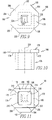
- the cover is shown generally at numeral 180.
- the cover includes an upper section 182 which has a top surface 184 and a lower surface 186 from which there projects a pin engagement structure generally at numeral 188 in the form of a substantially continuous wall 190.
- This wall is preferably, though not essentially, rectangular, and it has opposed end walls 192 and 194 and opposed side walls 196 and 198.
- This continuous wall also includes an inner peripheral side 200 and an outer peripheral 202.
- the upper section has an octangular peripheral side shown generally at numeral 204 which is made up of sides 206, 208, 210, 212, 214, 216, 218 and 220.
- a pick up cover has been described which allow the same cover to be used to engage a plurality of different pin arrays by merely pivoting that pick up cover on its vertical axis.
- a manufacturer of electrical or electronic devices may efficiently and economically transport and manipulate components being in place on a printed wiring board with only one or a small number of pick up covers rather than with separate pick up covers for each different type of header array.
Landscapes
- Engineering & Computer Science (AREA)
- Manufacturing & Machinery (AREA)
- Microelectronics & Electronic Packaging (AREA)
- Mechanical Engineering (AREA)
- Packaging Frangible Articles (AREA)
- Manufacturing Of Electrical Connectors (AREA)
- Manipulator (AREA)
Applications Claiming Priority (2)
| Application Number | Priority Date | Filing Date | Title |
|---|---|---|---|
| US08/607,970 US5810611A (en) | 1996-02-29 | 1996-02-29 | Pick up cover for use in transporting electrical headers |
| US607970 | 2000-06-30 |
Publications (1)
| Publication Number | Publication Date |
|---|---|
| EP0793409A1 true EP0793409A1 (de) | 1997-09-03 |
Family
ID=24434474
Family Applications (1)
| Application Number | Title | Priority Date | Filing Date |
|---|---|---|---|
| EP97103253A Withdrawn EP0793409A1 (de) | 1996-02-29 | 1997-02-27 | Deckel zur Beförderung von Verbindungsleisten |
Country Status (6)
| Country | Link |
|---|---|
| US (1) | US5810611A (de) |
| EP (1) | EP0793409A1 (de) |
| JP (1) | JPH1032073A (de) |
| KR (1) | KR970063825A (de) |
| SG (1) | SG68609A1 (de) |
| TW (1) | TW344498U (de) |
Cited By (1)
| Publication number | Priority date | Publication date | Assignee | Title |
|---|---|---|---|---|
| EP1231031A4 (de) * | 1999-10-29 | 2004-10-13 | Matsushita Electric Industrial Co Ltd | Saugdüse und verfahren und vorrichtung zum installieren von werkstücken mit dieser düse |
Families Citing this family (10)
| Publication number | Priority date | Publication date | Assignee | Title |
|---|---|---|---|---|
| US6099322A (en) * | 1997-10-31 | 2000-08-08 | The Whitaker Corporation | Electrical receptacle |
| DE19939770A1 (de) * | 1999-08-21 | 2001-02-22 | Weidmueller Interface | Verfahren zur Montage elektrischer Bauelemente auf einer Leiterplatte, Stiftleiste und Bestückungskopf |
| US6547609B2 (en) * | 2001-07-20 | 2003-04-15 | Hon Hai Precision Ind. Co., Ltd. | Vacuum pick up cap for using in socket |
| US6753474B2 (en) * | 2002-09-18 | 2004-06-22 | Tyco Electronics Corporation | Pick and place cover for multiple terminal electronic components |
| TW570383U (en) * | 2002-12-06 | 2004-01-01 | Hon Hai Prec Ind Co Ltd | Pick up mechanism for electrical connector |
| CN103972704A (zh) * | 2013-01-31 | 2014-08-06 | 鸿富锦精密电子(天津)有限公司 | 连接器保护罩 |
| USD805039S1 (en) * | 2015-01-29 | 2017-12-12 | Layer Zero Power Systems, Inc. | Cover |
| CN108249129A (zh) * | 2018-02-09 | 2018-07-06 | 东晶锐康晶体(成都)有限公司 | 一种校正取放产品位置机构 |
| US11605917B2 (en) * | 2020-09-14 | 2023-03-14 | Rockwell Automation Technologies, Inc. | Protective cover devices for protecting electrical connectors in industrial equipment |
| US11784554B2 (en) | 2020-09-14 | 2023-10-10 | Rockwell Automation Technologies, Inc. | Power conversion system with enhanced protection for gaseous corrosive atmospheres |
Citations (3)
| Publication number | Priority date | Publication date | Assignee | Title |
|---|---|---|---|---|
| US5317803A (en) * | 1991-05-30 | 1994-06-07 | Sierra Research And Technology, Inc. | Method of soldering an integrated circuit |
| EP0612204A2 (de) * | 1993-02-16 | 1994-08-24 | Molex Incorporated | Elektrischer Verbinder mit abziehbarem Deckel für das Positionieren, und Verfahren für deren Anwendung |
| WO1996017408A1 (en) * | 1994-11-28 | 1996-06-06 | Berg Technology Inc. | Vacuum pick-up device for header connector |
Family Cites Families (4)
| Publication number | Priority date | Publication date | Assignee | Title |
|---|---|---|---|---|
| JP2576105Y2 (ja) * | 1991-07-15 | 1998-07-09 | ケル株式会社 | コネクタの吸着用補助具 |
| JPH0744079Y2 (ja) * | 1991-12-09 | 1995-10-09 | モレックス インコーポレーテッド | 表面実装用コネクタ自動マウント用カバー |
| US5237739A (en) * | 1992-05-29 | 1993-08-24 | E. I. Du Pont De Nemours And Co. | Locating tool for power pins and receptacles |
| GB9407137D0 (en) * | 1994-04-11 | 1994-06-01 | Amp Gmbh | Electrical connector suction platform for facilitating picking |
-
1996
- 1996-02-29 US US08/607,970 patent/US5810611A/en not_active Expired - Fee Related
-
1997
- 1997-02-17 TW TW086202525U patent/TW344498U/zh unknown
- 1997-02-25 SG SG1997000469A patent/SG68609A1/en unknown
- 1997-02-27 KR KR1019970006328A patent/KR970063825A/ko not_active Withdrawn
- 1997-02-27 EP EP97103253A patent/EP0793409A1/de not_active Withdrawn
- 1997-02-27 JP JP9044200A patent/JPH1032073A/ja active Pending
Patent Citations (3)
| Publication number | Priority date | Publication date | Assignee | Title |
|---|---|---|---|---|
| US5317803A (en) * | 1991-05-30 | 1994-06-07 | Sierra Research And Technology, Inc. | Method of soldering an integrated circuit |
| EP0612204A2 (de) * | 1993-02-16 | 1994-08-24 | Molex Incorporated | Elektrischer Verbinder mit abziehbarem Deckel für das Positionieren, und Verfahren für deren Anwendung |
| WO1996017408A1 (en) * | 1994-11-28 | 1996-06-06 | Berg Technology Inc. | Vacuum pick-up device for header connector |
Cited By (1)
| Publication number | Priority date | Publication date | Assignee | Title |
|---|---|---|---|---|
| EP1231031A4 (de) * | 1999-10-29 | 2004-10-13 | Matsushita Electric Industrial Co Ltd | Saugdüse und verfahren und vorrichtung zum installieren von werkstücken mit dieser düse |
Also Published As
| Publication number | Publication date |
|---|---|
| TW344498U (en) | 1998-11-01 |
| JPH1032073A (ja) | 1998-02-03 |
| SG68609A1 (en) | 1999-11-16 |
| US5810611A (en) | 1998-09-22 |
| KR970063825A (ko) | 1997-09-12 |
Similar Documents
| Publication | Publication Date | Title |
|---|---|---|
| EP0793409A1 (de) | Deckel zur Beförderung von Verbindungsleisten | |
| DE4221017A1 (de) | Verbinder zum elektrischen verbinden von halbleiteranordnungen mit einem substrat | |
| US20040005800A1 (en) | ZIF socket connector having means for preventing CPU mounted on the connector from deformation due to a clamping force acting thereon | |
| EP0236125A2 (de) | Elektrischer Steckverbinder mit Arretiereigenschaft aufweisenden Stiften | |
| US5848703A (en) | Tray for integrated circuits | |
| GB2261330A (en) | Socket header of low height for connection to multiple pins | |
| JPH1032064A (ja) | 電気コネクタ | |
| JPH0650662B2 (ja) | スリップ・オフ電気コネクタ・ヘッダー | |
| JPH10510395A (ja) | ヘッダコネクタ用真空ピックアップ装置 | |
| US5651684A (en) | Vacuum pick up cap for use in manipulating receptacles | |
| US5032953A (en) | Surface mounted single in-line electronic component package with mounting projections and chamfered viewing edge | |
| JPS6182684A (ja) | 個々の導体のためのコネクタとその結線方法 | |
| US5022862A (en) | Modular connector | |
| US6345999B1 (en) | Connector and electronic component | |
| JP2022037909A (ja) | コンタクトレセプタクルを有する位置保証要素を含むコネクタ | |
| US5971785A (en) | Hermaphroditic connector for printed circuit boards | |
| JPH0332050A (ja) | Icパッケージ | |
| US6494747B1 (en) | Adapter socket | |
| US6045371A (en) | Connector for electrical connection of circuit boards and such a method for electrical connection of circuit boards using such a connector | |
| JPH0630266B2 (ja) | 低挿入力の電気コネクタ | |
| US7547223B2 (en) | Electrical connector with latching portion | |
| US20040115981A1 (en) | Connector packaging tray with supporting standoffs | |
| EP0166835A2 (de) | Von unten geladener elektrischer Sockel mit gleichmässiger Einsteck- und Ausnehmkraft | |
| WO2000070716A1 (en) | Multi way connector | |
| CA1099352A (en) | Electrical connector for circuit board |
Legal Events
| Date | Code | Title | Description |
|---|---|---|---|
| PUAI | Public reference made under article 153(3) epc to a published international application that has entered the european phase |
Free format text: ORIGINAL CODE: 0009012 |
|
| AK | Designated contracting states |
Kind code of ref document: A1 Designated state(s): DE FR GB |
|
| 17P | Request for examination filed |
Effective date: 19980116 |
|
| STAA | Information on the status of an ep patent application or granted ep patent |
Free format text: STATUS: THE APPLICATION IS DEEMED TO BE WITHDRAWN |
|
| 18D | Application deemed to be withdrawn |
Effective date: 20000830 |