EP0793059B1 - Regelungs- und Überwachungsschaltung eines Gasbrenners - Google Patents
Regelungs- und Überwachungsschaltung eines Gasbrenners Download PDFInfo
- Publication number
- EP0793059B1 EP0793059B1 EP97107692A EP97107692A EP0793059B1 EP 0793059 B1 EP0793059 B1 EP 0793059B1 EP 97107692 A EP97107692 A EP 97107692A EP 97107692 A EP97107692 A EP 97107692A EP 0793059 B1 EP0793059 B1 EP 0793059B1
- Authority
- EP
- European Patent Office
- Prior art keywords
- relay
- flame
- contact
- equipment
- shutdown
- Prior art date
- Legal status (The legal status is an assumption and is not a legal conclusion. Google has not performed a legal analysis and makes no representation as to the accuracy of the status listed.)
- Expired - Lifetime
Links
- 238000012544 monitoring process Methods 0.000 title claims abstract description 27
- 229910052751 metal Inorganic materials 0.000 claims abstract description 22
- 238000002485 combustion reaction Methods 0.000 claims abstract description 12
- 238000009423 ventilation Methods 0.000 claims description 28
- 102100028285 DNA repair protein REV1 Human genes 0.000 claims description 6
- 102100027700 DNA-directed RNA polymerase I subunit RPA2 Human genes 0.000 claims description 3
- 101000729474 Homo sapiens DNA-directed RNA polymerase I subunit RPA1 Proteins 0.000 claims description 3
- 101000650600 Homo sapiens DNA-directed RNA polymerase I subunit RPA2 Proteins 0.000 claims description 3
- 101001092206 Homo sapiens Replication protein A 32 kDa subunit Proteins 0.000 claims description 3
- 101001092125 Homo sapiens Replication protein A 70 kDa DNA-binding subunit Proteins 0.000 claims description 3
- 102100035729 Replication protein A 70 kDa DNA-binding subunit Human genes 0.000 claims description 3
- 230000015556 catabolic process Effects 0.000 claims description 2
- 230000003213 activating effect Effects 0.000 claims 1
- 238000011144 upstream manufacturing Methods 0.000 claims 1
- 238000010586 diagram Methods 0.000 description 14
- 101150016268 BLS1 gene Proteins 0.000 description 6
- 101100335694 Oryza sativa subsp. japonica G1L6 gene Proteins 0.000 description 6
- 230000000284 resting effect Effects 0.000 description 4
- XLYOFNOQVPJJNP-UHFFFAOYSA-N water Substances O XLYOFNOQVPJJNP-UHFFFAOYSA-N 0.000 description 4
- 101100411643 Saccharomyces cerevisiae (strain ATCC 204508 / S288c) RAD5 gene Proteins 0.000 description 3
- 230000008034 disappearance Effects 0.000 description 2
- 230000014759 maintenance of location Effects 0.000 description 2
- 239000002184 metal Substances 0.000 description 2
- 230000005662 electromechanics Effects 0.000 description 1
- 230000002427 irreversible effect Effects 0.000 description 1
- 238000000034 method Methods 0.000 description 1
- 238000012806 monitoring device Methods 0.000 description 1
- 230000001105 regulatory effect Effects 0.000 description 1
- 238000007789 sealing Methods 0.000 description 1
- 230000002123 temporal effect Effects 0.000 description 1
- 238000004804 winding Methods 0.000 description 1
Images

Classifications
-
- F—MECHANICAL ENGINEERING; LIGHTING; HEATING; WEAPONS; BLASTING
- F23—COMBUSTION APPARATUS; COMBUSTION PROCESSES
- F23N—REGULATING OR CONTROLLING COMBUSTION
- F23N5/00—Systems for controlling combustion
- F23N5/20—Systems for controlling combustion with a time programme acting through electrical means, e.g. using time-delay relays
- F23N5/203—Systems for controlling combustion with a time programme acting through electrical means, e.g. using time-delay relays using electronic means
-
- F—MECHANICAL ENGINEERING; LIGHTING; HEATING; WEAPONS; BLASTING
- F23—COMBUSTION APPARATUS; COMBUSTION PROCESSES
- F23N—REGULATING OR CONTROLLING COMBUSTION
- F23N5/00—Systems for controlling combustion
- F23N5/24—Preventing development of abnormal or undesired conditions, i.e. safety arrangements
- F23N5/242—Preventing development of abnormal or undesired conditions, i.e. safety arrangements using electronic means
-
- F—MECHANICAL ENGINEERING; LIGHTING; HEATING; WEAPONS; BLASTING
- F23—COMBUSTION APPARATUS; COMBUSTION PROCESSES
- F23N—REGULATING OR CONTROLLING COMBUSTION
- F23N5/00—Systems for controlling combustion
- F23N5/18—Systems for controlling combustion using detectors sensitive to rate of flow of air or fuel
- F23N2005/181—Systems for controlling combustion using detectors sensitive to rate of flow of air or fuel using detectors sensitive to rate of flow of air
- F23N2005/182—Air flow switch
-
- F—MECHANICAL ENGINEERING; LIGHTING; HEATING; WEAPONS; BLASTING
- F23—COMBUSTION APPARATUS; COMBUSTION PROCESSES
- F23N—REGULATING OR CONTROLLING COMBUSTION
- F23N2223/00—Signal processing; Details thereof
- F23N2223/22—Timing network
- F23N2223/24—Timing network with bimetallic elements
-
- F—MECHANICAL ENGINEERING; LIGHTING; HEATING; WEAPONS; BLASTING
- F23—COMBUSTION APPARATUS; COMBUSTION PROCESSES
- F23N—REGULATING OR CONTROLLING COMBUSTION
- F23N2223/00—Signal processing; Details thereof
- F23N2223/38—Remote control
-
- F—MECHANICAL ENGINEERING; LIGHTING; HEATING; WEAPONS; BLASTING
- F23—COMBUSTION APPARATUS; COMBUSTION PROCESSES
- F23N—REGULATING OR CONTROLLING COMBUSTION
- F23N2225/00—Measuring
- F23N2225/04—Measuring pressure
-
- F—MECHANICAL ENGINEERING; LIGHTING; HEATING; WEAPONS; BLASTING
- F23—COMBUSTION APPARATUS; COMBUSTION PROCESSES
- F23N—REGULATING OR CONTROLLING COMBUSTION
- F23N2225/00—Measuring
- F23N2225/08—Measuring temperature
-
- F—MECHANICAL ENGINEERING; LIGHTING; HEATING; WEAPONS; BLASTING
- F23—COMBUSTION APPARATUS; COMBUSTION PROCESSES
- F23N—REGULATING OR CONTROLLING COMBUSTION
- F23N2227/00—Ignition or checking
- F23N2227/04—Prepurge
-
- F—MECHANICAL ENGINEERING; LIGHTING; HEATING; WEAPONS; BLASTING
- F23—COMBUSTION APPARATUS; COMBUSTION PROCESSES
- F23N—REGULATING OR CONTROLLING COMBUSTION
- F23N2227/00—Ignition or checking
- F23N2227/36—Spark ignition, e.g. by means of a high voltage
-
- F—MECHANICAL ENGINEERING; LIGHTING; HEATING; WEAPONS; BLASTING
- F23—COMBUSTION APPARATUS; COMBUSTION PROCESSES
- F23N—REGULATING OR CONTROLLING COMBUSTION
- F23N2233/00—Ventilators
- F23N2233/06—Ventilators at the air intake
-
- F—MECHANICAL ENGINEERING; LIGHTING; HEATING; WEAPONS; BLASTING
- F23—COMBUSTION APPARATUS; COMBUSTION PROCESSES
- F23N—REGULATING OR CONTROLLING COMBUSTION
- F23N2235/00—Valves, nozzles or pumps
- F23N2235/12—Fuel valves
- F23N2235/14—Fuel valves electromagnetically operated
-
- F—MECHANICAL ENGINEERING; LIGHTING; HEATING; WEAPONS; BLASTING
- F23—COMBUSTION APPARATUS; COMBUSTION PROCESSES
- F23N—REGULATING OR CONTROLLING COMBUSTION
- F23N2235/00—Valves, nozzles or pumps
- F23N2235/12—Fuel valves
- F23N2235/18—Groups of two or more valves
-
- F—MECHANICAL ENGINEERING; LIGHTING; HEATING; WEAPONS; BLASTING
- F23—COMBUSTION APPARATUS; COMBUSTION PROCESSES
- F23N—REGULATING OR CONTROLLING COMBUSTION
- F23N5/00—Systems for controlling combustion
- F23N5/18—Systems for controlling combustion using detectors sensitive to rate of flow of air or fuel
Definitions
- the invention concerns a control and monitoring equipment for a gas burner applied to a heat generator.
- the best known burner control and monitoring equipments are suited to monitor different operation phases, such as the pre-ventilation of the combustion chamber where the burner operates, the ignition of the flame preceded by the opening of the solenoid valves for the inlet of the gas, the holding of said flame and a resting period whenever the reference figure of the physical value pre-set in the heat generator has been reached.
- European safety rules foresee an other safety device which provides a check of sealing of the gas valves. Said check can be provided before the cycle of the burner starts or when the reference figure of the physical pre-set value has been reached.
- the purpose of checking said valves is to verify that at least one valve is sealed. If one of the valves does not seal, the gas equipmet shuts off.
- the first one drawback is that this check system uses expensive devices, expecially for burners of low capacity.
- Another drawback consists in the fact that, when the reference figure of the physical value (i.e. temperature of the water) is reached and the flame of the burner does not stop, said check monitoring devices shut down preventing the burner to work.
- the reference figure of the physical value i.e. temperature of the water
- the purpose of the invention is to overcome the afore said drawbacks.
- the main purpose of the invention is to carry out a control and monitoring equipment for a gas burner which permits the working prefixed of the fan of the burner, if the flame remains after the shut down of the electrovalve which controls the flow of the gas when the prefixed temperature of the water of the heater is reached.
- control and monitoring equipment stops the motor of the fan of the burner after the disappearance of the flame.
- the electric powering of the motor of the electric fan supplying the combustion air keeps on, said powering action being insured by the closing of the contacts placed above the motor of the electric fan of a first relay belonging to the power circuit and excited by the closed position of a normally closed contact.
- Said normally closed contact belongs to a de-energized second relay inserted in the logic part of the equipment and placed in series to a first resistance wound around a bi-metallic element and in parallel with a closed contact belonging to the flame monitoring logic circuit.
- the energization of the motor of the electric fan stops when the flame for the commutation of the contact belonging to the flame monitoring logic circuit disappears.
- Said commutation excluds the short circuit of the aforesaid second relay placed in series to said first resistance and opens the normally closed contact of said second relay so as to interrupt the energization of said first relay and the open contacts of which de-energize the motor of the electric fan.
- the afore-said first resistance wound on a bi-metallic element according to the invention acts as an alternative of the shutdown relay should the flame disappear while the burner is in operation and should the shutdown relay break down.
- a preferred embodiment of the invention also foresees another resistance wound on the same bi-metallic element which allows the equipment to insure the performance of the electric fan even after the water temperature of the boiler has been reached when the equipment sensor has opened its contacts, should the flame sensor continue to detect the flame.
- a preferred embodiment of the invention also foresee another resistance interacting with another bi-metallic element which, with a proper circuit, will insure the shutdown of the equipment if there already is a flame when starting or if, during the pre-ventilation phase, the air necessary for the burner to work is insufficient.
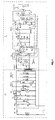
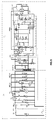
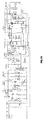
- the T relay is excited and, as a consequence, all the contacts T1, T2, T3 and T4 are closed.
- the B relay also called third relay, is also excited, then the B1 and B2 contacts also close.
- the Motor is energized through the PA contact which is connected with the air pressure sensor, which at this time does not sense the presence of air yet.
- the fan motor M is energized and the pre-ventilation phase begins.
- the air pressure sensor senses the presence of a sufficient pressure and the PA contact commutes, so as to excite the RPA2 relay.
- the fan motor M of the fan presents a secondary winding at the ends of which the VBT low tension is collected, said low tension energizing the entire logical part L for the monitoring of the equipment which, as can be observed in Fig.2 is to be found after the terminals 1, 2.
- the energization of the monitoring circuit entails the energization of the A RF logic circuit and, through the latter the RPA1 relay is also powered.
- the energization of said relay causes the 1RPA1 contact to close.
- the closing of the 1RPA1 contact makes it possible for the fan motor M to continue to be powered, even if in the meantime the PA contact has gone to its resting position from the energization of the motor to the energization of the RPA2 relay.
- the energization of the monitoring circuit of the equipment also entails the energizing of the t1 timer, which starts counting down a period of time, for instance of about 20 ⁇ 70 seconds, this occurring as a function of the RC time constant of the t1 circuit due to the R, R1 resistances placed in series and to the inner capacity of the logic circuit of t1.
- the energization of the t1 circuit closes through the 2RF contacts.
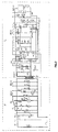
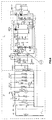
- the circuit of the equipment sends out a signal which opens the gas valves and also energizes a transformer connected with the spark.
- the ignition of the flame- must occur within a maximum time span of 3 seconds from the end of the pre-ventilation.
- a first signal t1 1 is sent out by the logic circuit which excites the RT relay and, as a consequence, its RT1 and RT2 contacts close. These contacts permit a retention current through the BL2 resistance, also called second resistance, through the 2RPA2, RT1, RT2, RTA contacts
- the contacts of said relay namely the 1 RTA and 2RTA contacts, close.
- the closing of the 1RTA contact causes the short circuit of the R resistance and, as a consequence, the variation of the RC time constant of the logic circuit of t1.
- the RC constant of the circuit changes from 20 ⁇ 70 seconds to a max. of 3 seconds.
- the closing of the 2RTA contact with the 3RF contact in its resting position causes the REV relay to be powered through the BLS1 resistance, also called first resistance.
- the feeding of the REV relay entails the closing of the 1REV contact and, therefore, the consequent energization of the REV1 relay placed in series with the RL relay. During this phase the RL relay is not excited.
- the corresponding EVS and EV1 solenoid valves for the gas distribution are open, the EVS valve being the safety valve placed before the two EV1 and EV2 valves.
- the 1REV1 contact also closes and, through the T3 contact and the 2RL contact, which is normally closed, it energizes the transformer energizing the TR spark. Therefore, all the conditions for the ignition of the flame are present, since the TR transformer energizing the spark and the EVS and EV1 solenoid valves for the gas distribution are being powered.
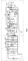
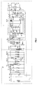
- the safety rules foresee a period of time not exceeding 3 seconds after the end of the pre-ventilation phase within which the flame must ignite. If the flame ignites, as can be observed in the diagram of Fig. 4, the A RF flame sensor senses the ignition and all the contacts 1 RF, 2RF, 3RF and 4RF, the last one being also called first contact, are commuted. By commuting the 2RF contact, the t1 timer stops being powered, so that the count down and any signal output are stopped.
- the RL relay By subsequently commuting the 3RF contact so that, as a consequence the first BLS1 resistance is no longer powered, the RL relay is fed at full voltage, so that the normally closed 2RL contact opens and the igniting spark stops because of the interruption of the energization of the TR transformer.
- the commutation of the 3RF contact causes the t2 timer to start counting, so that for the purpose of counting a signal is sent out such that it will excite the REV2 relay, as can be observed in Fig. 5.
- the EV2 solenoid valve also opens, since at the end of the count down by t2 the REV2 relay is excited and the 1REV2 contact energizes the EV2 solenoid valve. Therefore, during its normal operation, the burner is powered through the EVS safety valve and the EV1 and EV2 valves.
- the operation can be reset by the user by manually commuting the 1BL1 contact.
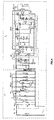
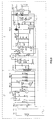
- the 1RTA and 2RTA contacts are also closed and, through the REV relay, energizes said first BLS1 resistance, which is a resistance wound around a bi-metallic rod, which begins to heat up because of the movement of the bi-metal. After a period varying from 3.1 to 5 seconds this bi-metallic rod on which BLS1 is wound will commute the BLG1 contact.
- This commutation interrupts the energization of the entire logic of the monitoring circuit and, as a consequence, also of the REV1 relay. This causes the opening of the 1REV1 contact which by opening stops the energization of the EVS and EV1 solenoid valves.
- the BLG1 contact the commutation of which has caused the shutdown of the equipment, is protected so that it can not be accessible to the user, but only to specialized personnel, whose intervention becomes necessary, since the commutation of the BLG1 contact has only occurred because of a failure of the BL shutdown relay, so that it becomes important to replace it.
- the M motor for the pre-ventilation begins to be powered.
- the countdown of the logic circuit t1 should also start.
- the presence of a flame which is sensed by the A RF circuit for the monitoring of the flame the 1RF, 2RF, 3RF 4RF contacts are commuted.
- the RC charge circuit of the time constant of the timer t1 is not closed at this point, so that it is not possible for the first impulse t1 1 to be sent out, since the countdown is interrupted.
- the RPA1 relay Since the A RF flame monitoring contact is excited, the RPA1 relay is also excited and, as a consequence, the 2RPA2 contact, also called second contact, is commuted and it permits, also through the closing of said first 4RF contact, the energization of said second BL shutdown relay through the second BL2 resistance, which is also wound around a bi-metallic element, deferring from the one previously described. Thus it occurs that if a flame is ignited at the start up, the equipment foresees the immediate shutdown.
- the T relay when the TL limit thermostat opens, the T relay is de-energized and, as a consequence, all the T1, T2, T3 and T4 contacts open.
- the opening of the T2 contact causes the solenoid valve of the REV2 relay to stop being energized.
- the corresponding EV2 solenoid valve is no longer energized. If no gas leaks out of the EVS safety solenoid valve, EV1 receives no gas, so that the flame goes out. If the flame goes out, the A RF relay commutes again and consequently the fourth E relay, which was kept in short circuit by the 2RF contact, is also excited.
- the corresponding 1E contact also opens and it causes the third B relay to open.
- the de-energizing of the third B relay causes also the opening of the contacts connected with said relay, i.e. the B1 and B2 contacts which cause the M motor to stop: it then occurs that after the contact TL of the limit thermostat has opened, the motor keeps on working only as long as the logic circuit which senses the presence of the flame insures that there is a flame.
- the system foresees that the motor, which supplies the combustion air, keeps supplying an amount of ventilation sufficient for the inlet gas to burn, thereby creating the ideal condition preventing dangerous situations due to the build-up of unburnt gas.
Landscapes
- Engineering & Computer Science (AREA)
- Chemical & Material Sciences (AREA)
- Combustion & Propulsion (AREA)
- Mechanical Engineering (AREA)
- General Engineering & Computer Science (AREA)
- Control Of Combustion (AREA)
- Regulation And Control Of Combustion (AREA)
- Feeding And Controlling Fuel (AREA)
Claims (8)
- Eine Steuer- und Kontrollanlage für Gasbrenner, geeignet, die folgenden Schritte zu steuern und zu kontrollieren: Vorlüftung der Brennerkammer, Zündung der Flamme, Halten der Flamme, Löschen der Flamme, wenn eine Einstelltemperatur eines zu erhitzenden Mediums erreicht ist, folgendes umfassend:dadurch gekennzeichnet, daß nach Erreichen der Temperatur des zu überwachenden Mediums, wenn die Flamme im Brenner weiterbrennt, nachdem die Leistungsversorgung des Solenoidventils (EVS) für die Gassicherheit unterbrochen wurde, die Energieversorgung des Motors (M) des elektrischen Lüfters, der die Brennluft liefert, aufrechterhalten bleibt, wobei diese Energieversorgung durch Schließung der Kontakte (B1, B2) eines ersten Relais (B) in der Kreisversorgung gewährleistet ist, welche den Motor (M) des elektrischen Lüfters versorgt, und das durch die geschlossene Position eines Ruhekontakts (1E) eines nicht mit Energie versorgten, zweiten Relais (E) im Logikteil der Anlage erregt wird, wobei dieses zweite Relais (E) reihengeschaltet mit einem ersten Widerstand (BLG) positioniert ist, der um ein Bimetallelement gewickelt ist und parallel mit einem Kontakt (2RF), kontrolliert durch den Flammenüberwachungs-Logikkreis (A RF), der sich schließen muß, wenn die Flamme erfaßt wird, wobei die Energieversorgung des Lüftermotors (M), unterbrochen wird, wenn keine Flamme erfaßt wird, und als Ergebnis den Kontakt (2RF), der durch den Flammenüberwachungs-Logikkreis (A RF) kontrolliert wird, umschaltet, wobei diese Umschaltung den Kurzschluß des zweiten Relais (E) beendet, das reihengeschaltet mit dem ersten Widerstand (BLG) positioniert ist und den Ruhekontakt (1 E) des zweiten Relais (E) öffnet, so daß die Energieversorgung des ersten Relais (B) unterbrochen wird, dessen offene Kontakte (B1, B2) die Versorgung des Motors (M) des elektrischen Lüfters unterbrechen (Fig. 10).A) Einen Leistungsteil (P), der folgendes umfaßt und über eine Versorgungsleitung versorgt:und weiterhin umfassend:den Elektromotor (M) von wenigstens einem elektrischen Lüfter, der die erforderliche Brennluft liefert;wenigstens ein Sicherheits-Solenoidventil (EVS), das stromaufwärts von wenigstens einem Solenoidventil (EV1) für die Gasausgabe positioniert ist;eine Vorrichtung (TR) für die Gaszündung;einen Sensor (TL) für die zu kontrollierende Temperatur des Mediums und einen Sensor (PA) für den Luftdruck im Brenner mit ihren jeweiligen elektrischen Kontakten (TL, PA), die an die Anlage angeschlossen sind;B) Einen Logikteil (L), folgendes umfassend:einen Logikkreis (ARF) zur Überwachung der Flamme;einen Logikkreis (t1) für die Rückwärtszählung der Vorlüftungszeit und eines Zündintervalls, innerhalb dessen eine Flamme erfaßt werden muß, wobei dieser Logikkreis einen ersten Impuls (t11) am Ende des Vorlüftungsschritts aussendet, mit dem die Öffnung der Solenoidventile (EVS, EV1) für die Gasausgabe bewirkt wird, und einen zweiten Impuls (t12), der das Zündungsintervall beendet und eine derartige Intensität aufweist, daß er ein erstes Abschaltrelais (BL) der Anlage in Leitfähigkeit versetzt, wenn die Flamme nicht erfaßt werden sollte,
- Eine Anlage gemäß Patentanspruch 1, dadurch gekennzeichnet, daß wenn die kontrollierte Temperatur einen Einstellwert erreicht hat und wenn eine Flamme erfaßt wurde, die Umschaltung eines Kontakts (BLG1), die mit dem Bimetallelement, um das der erste Widerstand (BLG) gewickelt ist, zusammenwirkt, eine Unterbrechung der Energieversorgung eines Relais (REV1) verursacht, zum Öffnen eines Kontakts (1REV1) in dem Kreis, der das noch geöffnete Solenoidventil (EV1) für die Gasausgabe mit Leistung versorgt, und dadurch dieses Ventil schließt.
- Eine Anlage gemäß Patentanspruch 1, dadurch gekennzeichnet, daß der erste Impuls (t11), der durch den Logikkreis (t1) ausgesendet wird, am Ende des Vorlüftungsschritts ein weiteres Relais (RTA) im Logikteil der Anlage mit Energie versorgt, dessen Kontakte (1RTA, 2RTA) einen Kreis schließen, der ein zweites Abschaltrelais (REV) über einen zweiten, um ein Bimetallelement gewickelten Widerstand (BLS1) versorgt, wobei letzterer mit einem umschaltbaren Kontakt (BLG1) zusammenwirkt und wobei diese Verbindung dazu führt, daß die Anlage abschaltet entweder durch Ansprechen des ersten Abschaltrelais (BL), das einen Kontakt (1BL1) in der Leistungsteil-Versorgungsleitung für die Versorgung der Anlage öffnet oder, bei Betriebsausfall des ersten Abschaltrelais (BL), durch Umschaltung des umschaltbaren Kontakts (BLG1), der mit dem Bimetallelement zusammenwirkt, das mit dem zweiten Widerstand (BLS1) gekoppelt ist (Fig. 6).
- Eine Anlage gemäß Patentanspruch 3, dadurch gekennzeichnet, daß der zweite, um ein Bimetallelement gewickelte Widerstand (BLS1) so bemessen ist, daß die Umschaltung des Kontakts (BLG1), der mit dem Bimetallelement zusammenwirkt, nach der Ausgabe des zweiten Impulses (t12) des Logikkreises für die Rückwärtszählung (t1) erfolgt, wenn die Flamme fehlt und wenn das Abschaltrelais (BL) der Anlage nicht anspricht (Fig. 6).
- Eine Anlage gemäß Patentanspruch 1, dadurch gekennzeichnet, daß das Fehlen der Flamme während des Brennerbetriebs ohne Öffnen des Kontakts (TL), der mit dem Sensor für die Messung der Mediumtemperatur verbunden ist, die Energieversorgung des Abschaltrelais (BL) verursacht, und eine zweiter Widerstand (BLS1), der um ein Bimetallelement gewickelt ist und geeignet ist, einen Kontakt (BLG1) durch Öffnen der weiteren Kontakte (1RF, 3RF) umzuschalten, wobei letztere durch den Flammenüberwachungs-Logikkreis (A RF) kontrolliert werden und diese weiteren Kontakte die Abschaltung der Anlage bewirken durch Unterbrechung der Versorgung des ersten Abschaltrelais (BL), das einen Kontakt (1BL1) in der Versorgungsleitung der Anlage öffnet oder, falls das Abschaltrelais (BL) nicht anspricht, über die Umschaltung des Kontakts (BLG1), der mit dem Bimetallelement verbunden ist, das mit dem zweiten Widerstand (BLS1) verbunden ist und eine Umschaltzeit aufweist, die länger ist als die Ansprechzeit des Abschaltrelais (Fig. 9).
- Eine Anlage gemäß Patentanspruch 1, dadurch gekennzeichnet, daß am Anfang des Vorgangs und wenn die Flamme vorhanden ist, der Flammenüberwachungs-Logikkreis (A RF) einen ersten Kontakt (4RF) umschaltet, der gemeinsam mit einem zweiten, durch ein Relais (RPA1) umgeschalteten Kontakt (2RPA2), der durch den Flammenüberwachungs-Logikkreis erregt wird, das erste Abschaltrelais (BL) über einen weiteren, um ein anderes Bimetallelement gewickelten Widerstand (BL2) mit Energie versorgt, wobei diese Verbindung die Abschaltung der Anlage über das Ansprechen des zweiten Abschaltrelais (REV) verursacht, das den Kontakt (1BL1) öffnet, welcher die Anlage versorgt (Fig. 7).
- Eine Anlage gemäß Patentanspruch 1, dadurch gekennzeichnet, daß wenn der Sensor (BA) des Luftdrucks während der Vorlüftung einen Luftmangel feststellt, die Kontakte (1RPA2, 2RPA2) eines Relais (RPA2), das mit dem Sensor (BA) verbunden ist, das erste Abschaltrelais (BL) über einen weiteren, um ein Bimetallelement gewickelten Widerstand (BL2) mit Energie versorgt, wobei diese Verbindung die Abschaltung der Anlage über das Ansprechen des ersten Abschaltrelais (BL) verursacht, das einen Kontakt (1BL1) in der Leistungsversorgungsleitung der Anlage öffnet (Fig. 8).
- Eine Anlage gemäß Patentanspruch 1 oder 3 oder 6, dadurch gekennzeichnet, daß der erste und der zweite Widerstand (BLS1, BLG), die jeweils nach dem Ende der Verbrennung ansprechen, wenn die Flamme brennt, sowie im Fall einer Störung der Zeitgeberlogik am Ende der Vorlüftung, um dasselbe Bimetallelement gewickelt sind, das denselben Kontakt aktiviert (BLG1).
Applications Claiming Priority (3)
| Application Number | Priority Date | Filing Date | Title |
|---|---|---|---|
| ITVI920148A IT1259837B (it) | 1992-10-07 | 1992-10-07 | Apparecchiatura di controllo e comando per bruciatori a gas |
| ITVI920148 | 1992-10-07 | ||
| EP93116050A EP0591910B1 (de) | 1992-10-07 | 1993-10-05 | Regelungs- und Überwachungsschaltung eines Gasbrenners |
Related Parent Applications (2)
| Application Number | Title | Priority Date | Filing Date |
|---|---|---|---|
| EP93116050.1 Division | 1993-10-05 | ||
| EP93116050A Division EP0591910B1 (de) | 1992-10-07 | 1993-10-05 | Regelungs- und Überwachungsschaltung eines Gasbrenners |
Publications (3)
| Publication Number | Publication Date |
|---|---|
| EP0793059A2 EP0793059A2 (de) | 1997-09-03 |
| EP0793059A3 EP0793059A3 (de) | 1997-10-01 |
| EP0793059B1 true EP0793059B1 (de) | 2000-02-02 |
Family
ID=11425013
Family Applications (2)
| Application Number | Title | Priority Date | Filing Date |
|---|---|---|---|
| EP97107692A Expired - Lifetime EP0793059B1 (de) | 1992-10-07 | 1993-10-05 | Regelungs- und Überwachungsschaltung eines Gasbrenners |
| EP93116050A Expired - Lifetime EP0591910B1 (de) | 1992-10-07 | 1993-10-05 | Regelungs- und Überwachungsschaltung eines Gasbrenners |
Family Applications After (1)
| Application Number | Title | Priority Date | Filing Date |
|---|---|---|---|
| EP93116050A Expired - Lifetime EP0591910B1 (de) | 1992-10-07 | 1993-10-05 | Regelungs- und Überwachungsschaltung eines Gasbrenners |
Country Status (4)
| Country | Link |
|---|---|
| EP (2) | EP0793059B1 (de) |
| AT (1) | ATE165434T1 (de) |
| DE (2) | DE69327811D1 (de) |
| IT (1) | IT1259837B (de) |
Family Cites Families (8)
| Publication number | Priority date | Publication date | Assignee | Title |
|---|---|---|---|---|
| US3488131A (en) * | 1964-10-26 | 1970-01-06 | Whirlpool Co | Electronic spark ignitor control for fuel burner |
| US3524717A (en) * | 1968-06-17 | 1970-08-18 | Electronics Corp America | Combustion supervision system |
| US3574495A (en) * | 1969-12-11 | 1971-04-13 | Honeywell Inc | Burner control system |
| CA1096464A (en) * | 1977-03-07 | 1981-02-24 | Russell B. Matthews | Fuel ignition system having interlock protection and electronic valve leak detection |
| US4243372A (en) * | 1979-02-05 | 1981-01-06 | Electronics Corporation Of America | Burner control system |
| US4482312A (en) * | 1979-06-20 | 1984-11-13 | Electronics Corporation Of America | Burner control system |
| DE3022635C2 (de) * | 1980-06-18 | 1984-11-22 | Danfoss A/S, Nordborg | Steuerschaltung für eine Feuerungsanlage |
| US4976459A (en) * | 1990-02-09 | 1990-12-11 | Inter-City Products Corporation (Usa) | Warmup method for a two stage furnace |
-
1992
- 1992-10-07 IT ITVI920148A patent/IT1259837B/it active IP Right Grant
-
1993
- 1993-10-05 EP EP97107692A patent/EP0793059B1/de not_active Expired - Lifetime
- 1993-10-05 DE DE69327811T patent/DE69327811D1/de not_active Expired - Lifetime
- 1993-10-05 DE DE69318092T patent/DE69318092D1/de not_active Expired - Lifetime
- 1993-10-05 AT AT93116050T patent/ATE165434T1/de not_active IP Right Cessation
- 1993-10-05 EP EP93116050A patent/EP0591910B1/de not_active Expired - Lifetime
Also Published As
| Publication number | Publication date |
|---|---|
| DE69327811D1 (de) | 2000-03-09 |
| EP0793059A2 (de) | 1997-09-03 |
| ITVI920148A1 (it) | 1994-04-07 |
| EP0793059A3 (de) | 1997-10-01 |
| EP0591910B1 (de) | 1998-04-22 |
| EP0591910A1 (de) | 1994-04-13 |
| IT1259837B (it) | 1996-03-28 |
| ITVI920148A0 (it) | 1992-10-07 |
| DE69318092D1 (de) | 1998-05-28 |
| ATE165434T1 (de) | 1998-05-15 |
Similar Documents
| Publication | Publication Date | Title |
|---|---|---|
| EP0385910B1 (de) | Kontrollverfahren für Kraftstoffbrenner mit heisser Oberflächenzündung | |
| CA1166719A (en) | Self-checking safety switch control circuit | |
| CA1116720A (en) | Fail-safe gas feed and ignition sequence control apparatus and method for a gas-fired appliance | |
| US3277949A (en) | Apparatus for hydrocarbon ignition and monitoring | |
| US3488131A (en) | Electronic spark ignitor control for fuel burner | |
| US3086583A (en) | Burner control apparatus | |
| US5169301A (en) | Control system for gas fired heating apparatus using radiant heat sense | |
| US4077762A (en) | Fuel ignition system having contact interlock protection | |
| US4106889A (en) | Burner ignition system | |
| US4850852A (en) | Gas valve shut off method and apparatus | |
| US3484177A (en) | Igniter and control means | |
| EP0793059B1 (de) | Regelungs- und Überwachungsschaltung eines Gasbrenners | |
| US4147496A (en) | Safety ignition means for burner installations | |
| US3059693A (en) | Control system | |
| US3443752A (en) | Control system for gas-fired heating apparatus | |
| US3432246A (en) | Electrical flame ignition and supervising apparatus | |
| US3245456A (en) | Control system for fluid fuel burners | |
| KR930006171B1 (ko) | 연소제어장치 | |
| US4078878A (en) | Fuel burner control device providing safely ignited burner | |
| US4168141A (en) | Safety ignition means for burner installations | |
| JPH08145355A (ja) | 燃焼制御装置 | |
| JPS6027898B2 (ja) | 燃焼制御装置 | |
| JPH08147051A (ja) | 電源制御装置 | |
| US3320998A (en) | Electric control of fuel-burning devices | |
| JP2768635B2 (ja) | 燃焼装置 |
Legal Events
| Date | Code | Title | Description |
|---|---|---|---|
| PUAI | Public reference made under article 153(3) epc to a published international application that has entered the european phase |
Free format text: ORIGINAL CODE: 0009012 |
|
| PUAL | Search report despatched |
Free format text: ORIGINAL CODE: 0009013 |
|
| AC | Divisional application: reference to earlier application |
Ref document number: 591910 Country of ref document: EP |
|
| AK | Designated contracting states |
Kind code of ref document: A2 Designated state(s): CH DE FR GB IT LI |
|
| RIN1 | Information on inventor provided before grant (corrected) |
Inventor name: TAGLIAFERRO, BRUNO Inventor name: FERRARI, ALBERTO Inventor name: BORELLI, LUIGI |
|
| AK | Designated contracting states |
Kind code of ref document: A3 Designated state(s): CH DE FR GB IT LI |
|
| 17P | Request for examination filed |
Effective date: 19971106 |
|
| 17Q | First examination report despatched |
Effective date: 19981210 |
|
| GRAG | Despatch of communication of intention to grant |
Free format text: ORIGINAL CODE: EPIDOS AGRA |
|
| GRAG | Despatch of communication of intention to grant |
Free format text: ORIGINAL CODE: EPIDOS AGRA |
|
| GRAH | Despatch of communication of intention to grant a patent |
Free format text: ORIGINAL CODE: EPIDOS IGRA |
|
| GRAH | Despatch of communication of intention to grant a patent |
Free format text: ORIGINAL CODE: EPIDOS IGRA |
|
| GRAA | (expected) grant |
Free format text: ORIGINAL CODE: 0009210 |
|
| AC | Divisional application: reference to earlier application |
Ref document number: 591910 Country of ref document: EP |
|
| AK | Designated contracting states |
Kind code of ref document: B1 Designated state(s): CH DE FR GB IT LI |
|
| PG25 | Lapsed in a contracting state [announced via postgrant information from national office to epo] |
Ref country code: LI Free format text: LAPSE BECAUSE OF FAILURE TO SUBMIT A TRANSLATION OF THE DESCRIPTION OR TO PAY THE FEE WITHIN THE PRESCRIBED TIME-LIMIT Effective date: 20000202 Ref country code: IT Free format text: LAPSE BECAUSE OF FAILURE TO SUBMIT A TRANSLATION OF THE DESCRIPTION OR TO PAY THE FEE WITHIN THE PRE;WARNING: LAPSES OF ITALIAN PATENTS WITH EFFECTIVE DATE BEFORE 2007 MAY HAVE OCCURRED AT ANY TIME BEFORE 2007. THE CORRECT EFFECTIVE DATE MAY BE DIFFERENT FROM THE ONE RECORDED.SCRIBED TIME-LIMIT Effective date: 20000202 Ref country code: FR Free format text: LAPSE BECAUSE OF FAILURE TO SUBMIT A TRANSLATION OF THE DESCRIPTION OR TO PAY THE FEE WITHIN THE PRESCRIBED TIME-LIMIT Effective date: 20000202 Ref country code: CH Free format text: LAPSE BECAUSE OF FAILURE TO SUBMIT A TRANSLATION OF THE DESCRIPTION OR TO PAY THE FEE WITHIN THE PRESCRIBED TIME-LIMIT Effective date: 20000202 |
|
| REG | Reference to a national code |
Ref country code: CH Ref legal event code: EP |
|
| REF | Corresponds to: |
Ref document number: 69327811 Country of ref document: DE Date of ref document: 20000309 |
|
| PG25 | Lapsed in a contracting state [announced via postgrant information from national office to epo] |
Ref country code: DE Free format text: LAPSE BECAUSE OF FAILURE TO SUBMIT A TRANSLATION OF THE DESCRIPTION OR TO PAY THE FEE WITHIN THE PRESCRIBED TIME-LIMIT Effective date: 20000503 |
|
| EN | Fr: translation not filed | ||
| PG25 | Lapsed in a contracting state [announced via postgrant information from national office to epo] |
Ref country code: GB Free format text: LAPSE BECAUSE OF NON-PAYMENT OF DUE FEES Effective date: 20001005 |
|
| PLBE | No opposition filed within time limit |
Free format text: ORIGINAL CODE: 0009261 |
|
| STAA | Information on the status of an ep patent application or granted ep patent |
Free format text: STATUS: NO OPPOSITION FILED WITHIN TIME LIMIT |
|
| 26N | No opposition filed | ||
| GBPC | Gb: european patent ceased through non-payment of renewal fee |
Effective date: 20001005 |