EP0792968B1 - Disposition for holding down a nose of crossing - Google Patents
Disposition for holding down a nose of crossing Download PDFInfo
- Publication number
- EP0792968B1 EP0792968B1 EP97103343A EP97103343A EP0792968B1 EP 0792968 B1 EP0792968 B1 EP 0792968B1 EP 97103343 A EP97103343 A EP 97103343A EP 97103343 A EP97103343 A EP 97103343A EP 0792968 B1 EP0792968 B1 EP 0792968B1
- Authority
- EP
- European Patent Office
- Prior art keywords
- support
- wing
- frog point
- wing rails
- arrangement according
- Prior art date
- Legal status (The legal status is an assumption and is not a legal conclusion. Google has not performed a legal analysis and makes no representation as to the accuracy of the status listed.)
- Expired - Lifetime
Links
Images

Classifications
-
- E—FIXED CONSTRUCTIONS
- E01—CONSTRUCTION OF ROADS, RAILWAYS, OR BRIDGES
- E01B—PERMANENT WAY; PERMANENT-WAY TOOLS; MACHINES FOR MAKING RAILWAYS OF ALL KINDS
- E01B7/00—Switches; Crossings
- E01B7/10—Frogs
- E01B7/14—Frogs with movable parts
Definitions
- the invention relates to an arrangement for holding down a between wing rails running centerpiece tip that can be supported on a base such as a sliding chair, in particular movable and spring-movable centerpiece tip of a crossover core or crossing.
- a linkage starts from a centerpiece for grooved rail switches from, which penetrates wing rails and over which the centerpiece is adjustable.
- DE-AS 1 272 951 describes a pivotable centerpiece that has a linkage running below wing rails is adjustable.
- Spring-moving centerpiece tips or those that are elastically supported are also from the DE 37 08 233 A1 known.
- WO 94/19542 and DE 43 05 228 A1 describe one known spring-moving centerpiece tip, which starts from a driver device, which itself is supported on the underside of the wing rails so that a quasi rigid unit is formed.
- the driver device which is indirect Belleville washers supported against the centerpiece tip, lifted off the wing rails.
- the problem underlying the present invention is an arrangement for holding down to develop a centerpiece tip of the type described in the introduction in such a way that it is constructive simple measures a safe hold down of the frog tip is guaranteed, whereby At the same time, it should be ensured that for adjusting the centerpiece tip by a wing rail to the other wing rail a desired smoothness is given without in addition to the centerpiece tip, additional masses have to be moved.
- the problem is solved in that the frog tip is penetrated by an element that is used to hold down the centerpiece tip in the direction of the Underlay is subjected to force, and that for adjusting the frog tip, the element in an opening penetrated by this in the frog tip can be raised or so is rotatable that it is adjustable to the desired extent.
- the element penetrates both the frog tip and the wing rails, the Element of a bracket extending in sections below the wing rails goes out, the underside via at least one spring element on at least one wing rail foot is supported.
- the centerpiece tip that is, the element in the opening of the To shift the centerpiece tip in such a way that the element does not hinder the adjustment movement can, it is provided that the holder via an assembly upwards, that is in the direction of Wing rail head is adjustable.
- the element itself is preferably rod-shaped and has in the adjustment path Intermediate protruding sections such as cams on, from one of them holding down the centerpiece tip in her on one of the wing rails supported position in the bottom area of the opening. This will make it a safe one The tip of the centerpiece is held down without the element being supported flatly must take place in the opening.
- the holder includes one below the Wing rails extending plate-shaped section, such as spring elements Disc springs are supported on the underside of the wing rail feet.
- the plate-shaped section of the bracket the aggregate like a piston-cylinder arrangement to the plate-shaped section opposite to that caused by the spring elements To be able to adjust force, whereby the spring elements are compressed.
- a piston-cylinder arrangement can of course also be another unit such as Servomotor can be used or moving can be done by means of a magnet.
- the bracket itself extends on the outside along the wing rails and has clamping jaws to grasp the rod-shaped element. Furthermore, the holder in the area of Rail feet of the wing rails a clear distance that is greater than the distance between outer edges of the wing rail feet. This ensures that the Wing rail feet do not hinder the up and down movement of the bracket.
- the unit itself can be based on a bracket that can be used directly or indirectly with the Wing rails are connected. So the holder of a ribbed plate or of Supports the wing rails like thresholds. Preferably, the bracket is over Clamping jaws fixed to the wing rail feet.
- the rod-shaped element has projections like cams, which by rotating the element the frog tip in the direction of Apply force to the pad or to which the centerpiece tip is adjustable.
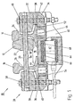
- the figures show sections through a centerpiece tip 10.
- the centerpiece tip usually includes a movable frog block 12 which is between wing rails 14 and 16 runs.
- the frog block or frog tip 12 is on a sliding chair 18 supported, which in the exemplary embodiment as inner rail bracing for the wing rails 14 and 16 is formed.
- the wing rails 14 and 16 themselves are not shown on Supported documents such as ribbed plates, which in turn are based on supports such as sleepers are arranged. In this respect, however, is based on well-known track superstructures referred.
- the frog tip 12 on the wing rail 14 - as shown - or on the Wing rail 16 is a preferably rod-shaped element provided that both the frog tip 12 and the wing rails 14, 16 in Openings 22, 24 and 26 interspersed.
- the openings 22, 24 and 26 are aligned to each other.
- the rod element 22 is based on a holder 28, which in the exemplary embodiment outer jaws 30, 32, via which the rod element 20 is clamped, and a below the wing rails 14 and 16 extending plate-shaped section as a base plate 34 includes.
- the bracket consequently has a section comprising the wing rails 14, 16 U geometry on.
- the jaws 30, 32, the spacers or intermediate plates 36, 38 and the base plate 34 are connected or clamped to one another via bolts or screws 48, 50.
- the bottom plate 34 of the holder 28 runs at a distance from the underside of the feet 44, 46 of the Wing rails 14 and 16. Furthermore, the base plate 34 and thus the holder 28 are opposite the wing rails 14 and 16 are supported by spring elements such as plate springs 52, 54. As The result is the holder 28 or the rod element 20 downwards, that is in the direction of Slide chair 18 or the feet 44, 46 of the wing rails 14, 16 pulled. Due to this the rod element 20 is supported on the bottom area of the opening 22 of the frog tip 12 from, so that the frog tip 12 is held down on the sliding chair 18. In contrast the rod element 20 passes through the opening 24, 26 of the wing rails 14, 16 spaced.
- this shows Rod element 20 in the direction of the sliding chair 18 extending projections such as cams 56, 58th on, which are then supported on the bottom of the opening 22 of the frog tip 12 when the Centerpiece tip 12 rests on the wing rail 14 or on the wing rail 16.
- the bracket 28 can be raised to an extent that the Bar element 20 the opening 22 of the frog tip 12 largely spaced enforced.
- the Bottom plate 34 a force applied by which the plate springs 52 and 54 are compressed become.
- an adjustment unit in the form of a cylinder-piston arrangement goes from a holder 60 from, the piston 64 via an elastic intermediate layer 66 in one recess 68 on the bottom engages from the base plate 34.
- the piston of the unit 62 displaced the base plate 34 is consequently raised against the spring force, whereby the rod element 22 is raised and thus the centerpiece tip 12 moves easily from the Wing rail 14 can be adjusted to wing rail 16 or vice versa.
- the rod element 20 passes through Openings 24, 26 of the wing rails 14, 16 always with play.
- the bracket 60 for the drive unit 62 starts from the wing rail feet 44, 46, as Fig. 2 illustrates.
- the holder 60 is held in the unit 62 is fixed, connected to the wing rail feet 44, 46 via clamping jaws 72, 74.
- a plate 76 runs between the underside of the rail feet 44, 46 and the receptacle 70.
Landscapes
- Engineering & Computer Science (AREA)
- Mechanical Engineering (AREA)
- Architecture (AREA)
- Civil Engineering (AREA)
- Structural Engineering (AREA)
- Chairs For Special Purposes, Such As Reclining Chairs (AREA)
- Surgical Instruments (AREA)
- Chairs Characterized By Structure (AREA)
- Carriages For Children, Sleds, And Other Hand-Operated Vehicles (AREA)
- Dental Tools And Instruments Or Auxiliary Dental Instruments (AREA)
- Brushes (AREA)
- Ladders (AREA)
- Orthopedics, Nursing, And Contraception (AREA)
Abstract
Description
Die Erfindung bezieht sich auf eine Anordnung zum Niederhalten einer zwischen Flügelschienen verlaufenden und auf einer Unterlage wie Gleitstuhl abstützbaren Herzstückspitze, insbesondere beweglicher wie federbeweglicher Herzstückspitze eines Herzstücks einer Weiche oder Kreuzung.The invention relates to an arrangement for holding down a between wing rails running centerpiece tip that can be supported on a base such as a sliding chair, in particular movable and spring-movable centerpiece tip of a crossover core or crossing.
Bei den heutzutage üblichen federbeweglichen Herzstücken wird die Herzstückspitze oder der Herzstückblock zwischen Flügelschienen auf einer Unterlage wie Gleitstuhl abgestützt, wohingegen die Flügelschienen weitgehend ortsfest von Unterlagen wie Rippenplatten ausgehen. Auch besteht die Möglichkeit, Flügelschienen fest auf Gleistühlen, auf denen die Herzstückspitze verschoben wird, zu befestigen.In the spring-moving frogs common today, the frog tip or the Centerpiece block supported between wing rails on a base such as a sliding chair, whereas the wing rails are largely stationary from documents such as rib plates going out. There is also the possibility of fixed wing rails on slide chairs on which the Centerpiece tip is moved to attach.
Nach der DE 23 30 828C2 geht von einem Herzstück für Rillenschienenweichen ein Gestänge aus, das Flügelschienen durchsetzt und über das das Herzstück verstellbar ist.According to DE 23 30 828C2, a linkage starts from a centerpiece for grooved rail switches from, which penetrates wing rails and over which the centerpiece is adjustable.
In der DE-AS 1 272 951 wird ein verschwenkbares Herzstück beschrieben, das über ein unterhalb von Flügelschienen verlaufendes Gestänge verstellbar ist. DE-AS 1 272 951 describes a pivotable centerpiece that has a linkage running below wing rails is adjustable.
Federbewegliche Herzstückspitzen bzw. solche, die elastisch abgestützt sind, sind auch aus der DE 37 08 233 A1 bekannt.Spring-moving centerpiece tips or those that are elastically supported are also from the DE 37 08 233 A1 known.
Beim Einleiten von Schwingungen in Richtung der Mittelachsen der Gleiskörper kann eine Relativbewegung zwischen Herstückspitze und Flügelschienen im Bereich zwischen dem Gleitstuhl bzw. Rippenplatten, von denen die Flügelschienen ausgehen, auftreten.When vibrations are introduced in the direction of the central axes of the track body, a Relative movement between the tip and wing rails in the area between the Sliding chair or ribbed plates from which the wing rails originate occur.
Hierdurch können sich unterschiedliche Bedingungen im Überlaufbereich des Rades zwischen Herzstückspitze und Flügelschienen ausbilden. Dies wiederum hat zur Folge, dass die Herzstückspitze einem unerwünschten Verschleiß unterworfen ist.This can result in different conditions in the overflow area of the wheel Form the centerpiece tip and wing rails. This in turn means that the centerpiece tip is subject to undesirable wear.
Um diese Nachteile zu vermeiden, ist aus der WO 94/19542 bzw. DE 43 05 228 A1 eine federbewegliche Herzstückspitze bekannt, die von einer Mitnehmereinrichtung ausgeht, die sich unterseitig an den Flügelschienen abstützt, so dass sich eine quasi starre Einheit ausbildet. Um jedoch ein leichtgängiges Verstellen der Herzstückspitze von der einen Flügelschiene zur anderen Flügelschiene zu ermöglichen, wird die Mitnehmereinrichtung, die mittelbar über Tellerfedern gegenüber der Herzstückspitze abgestützt ist, von den Flügelschienen abgehoben.In order to avoid these disadvantages, WO 94/19542 and DE 43 05 228 A1 describe one known spring-moving centerpiece tip, which starts from a driver device, which itself is supported on the underside of the wing rails so that a quasi rigid unit is formed. Around however, an easy adjustment of the centerpiece tip from one wing rail to To enable another wing rail, the driver device, which is indirect Belleville washers supported against the centerpiece tip, lifted off the wing rails.
Der vorliegenden Erfindung liegt das Problem zugrunde, eine Anordnung zum Niederhalten einer Herzstückspitze der eingangs beschriebenen Art so weiterzubilden, dass mit konstruktiv einfachen Maßnahmen ein sicheres Niederhalten der Herzstückspitze gewährleistet ist, wobei gleichzeitig sichergestellt sein soll, dass zum Verstellen der Herzstückspitze von einer Flügelschiene zur anderen Flügelschiene eine gewünschte Leichtgängigkeit gegeben ist, ohne dass neben der Herzstückspitze zusätzliche Massen bewegt werden müssen.The problem underlying the present invention is an arrangement for holding down to develop a centerpiece tip of the type described in the introduction in such a way that it is constructive simple measures a safe hold down of the frog tip is guaranteed, whereby At the same time, it should be ensured that for adjusting the centerpiece tip by a wing rail to the other wing rail a desired smoothness is given without in addition to the centerpiece tip, additional masses have to be moved.
Das Problem wird erfindungsgemäß dadurch gelöst, dass die Herzstückspitze von einem Element durchsetzt ist, das zum Niederhalten der Herzstückspitze in Richtung der Unterlage kraftbeaufschlagt ist, und dass zum Verstellen der Herzstückspitze das Element in einer von diesem durchsetzten Durchbrechung in der Herzstückspitze derart anhebbar oder drehbar ist, dass diese im gewünschten Umfang verstellbar ist. Insbesondere ist vorgesehen, dass das Element sowohl die Herzstückspitze als auch die Flügelschienen durchsetzt, wobei das Element von einer sich abschnittsweise unterhalb der Flügelschienen erstreckenden Halterung ausgeht, die unterseitig über zumindest ein Federelement an zumindest einem Flügelschienenfuß abgestützt ist.According to the invention, the problem is solved in that the frog tip is penetrated by an element that is used to hold down the centerpiece tip in the direction of the Underlay is subjected to force, and that for adjusting the frog tip, the element in an opening penetrated by this in the frog tip can be raised or so is rotatable that it is adjustable to the desired extent. In particular, it is provided that the element penetrates both the frog tip and the wing rails, the Element of a bracket extending in sections below the wing rails goes out, the underside via at least one spring element on at least one wing rail foot is supported.
Um die Herzstückspitze verstellen zu können, um also das Element in der Durchbrechung der Herzstückspitze derart zu verlagern, dass das Element die Verstellbewegung nicht behindern kann, ist vorgesehen, dass die Halterung über ein Aggregat nach oben, also in Richtung des Flügelschienenkopfes verstellbar ist.In order to be able to adjust the centerpiece tip, that is, the element in the opening of the To shift the centerpiece tip in such a way that the element does not hinder the adjustment movement can, it is provided that the holder via an assembly upwards, that is in the direction of Wing rail head is adjustable.
Das Element selbst ist vorzugsweise stabförmig ausgebildet und weist im Verstellweg der Herzstückspitze in Richtung der Unterlage vorspringende Abschnitte wie Nocken auf, von denen sich eine beim Niederhalten der Herzstückspitze in ihrer an einer der Flügelschienen anliegenden Stellung im Bodenbereich der Durchbrechung abstützt. Hierdurch wird ein sicheres Niederhalten der Herzstückspitze gewährleistet, ohne dass ein flächiges Abstützen des Elements in der Durchbrechung erfolgen muss.The element itself is preferably rod-shaped and has in the adjustment path Intermediate protruding sections such as cams on, from one of them holding down the centerpiece tip in her on one of the wing rails supported position in the bottom area of the opening. This will make it a safe one The tip of the centerpiece is held down without the element being supported flatly must take place in the opening.
Nach einem weiteren vorteilhaften Vorschlag der Erfindung umfasst die Halterung einen sich unterhalb der Flügelschienen erstreckenden plattenförmigen Abschnitt, der über Federelemente wie Tellerfedern unterseitig an den Flügelschienenfüßen abgestützt ist. Ferner greift an den plattenförmigen Abschnitt der Halterung das Aggregat wie eine Kolben-Zylinder-Anordnung an, um den plattenförmigen Abschnitt entgegen der von den Federelementen hervorgerufenen Kraft verstellen zu können, wodurch die Federelemente zusammengedrückt werden. Anstelle einer Kolben-Zylinder-Anordnung kann selbstverständlich auch ein sonstiges Aggregat wie Stellmotor eingesetzt werden oder ein Verschieben kann mittels eines Magneten erfolgen.According to a further advantageous proposal of the invention, the holder includes one below the Wing rails extending plate-shaped section, such as spring elements Disc springs are supported on the underside of the wing rail feet. Furthermore, the plate-shaped section of the bracket the aggregate like a piston-cylinder arrangement to the plate-shaped section opposite to that caused by the spring elements To be able to adjust force, whereby the spring elements are compressed. Instead of A piston-cylinder arrangement can of course also be another unit such as Servomotor can be used or moving can be done by means of a magnet.
Die Halterung selbst erstreckt sich außenseitig entlang der Flügelschienen und weist Klemmbacken zum Erfassen des stabförmigen Elements auf. Ferner weist die Halterung im Bereich der Schienenfüße der Flügelschienen einen lichten Abstand auf, der größer als der Abstand zwischen äußeren Rändern der Flügelschienenfüße ist. Hierdurch ist sichergestellt, dass die Flügelschienenfüße die Auf- und Abbewegung der Halterung nicht behindern.The bracket itself extends on the outside along the wing rails and has clamping jaws to grasp the rod-shaped element. Furthermore, the holder in the area of Rail feet of the wing rails a clear distance that is greater than the distance between outer edges of the wing rail feet. This ensures that the Wing rail feet do not hinder the up and down movement of the bracket.
Damit beim Anheben bzw. Absenken des stabförmigen Elementes zum Niederhalten bzw. Freigeben der Herzstückspitze die Flügelschienen nicht beeinflußt werden können, ist des weiteren vorgesehen, dass unabhängig von der Stellung des stabförmigen Elementes dieses Durchbrechungen der Flügelschienen stets beabstandet durchsetzt.So that when raising or lowering the rod-shaped element for holding down or Releasing the frog tip the wing rails can not be influenced is the further provided that regardless of the position of the rod-shaped element Breakthroughs in the wing rails are always spaced apart.
Das die Halterung entgegen der von den Federelementen hervorgerufenen Kraft verstellende Aggregat selbst kann von einer Halterung ausgehen, die mittelbar oder unmittelbar mit den Flügelschienen in Verbindung steht. So kann die Halterung von einer Rippenplatte oder von Abstützungen der Flügelschienen wie Schwellen ausgehen. Vorzugsweise ist die Halterung über Klemmbacken an den Flügelschienenfüßen fixiert.That adjusts the holder against the force caused by the spring elements The unit itself can be based on a bracket that can be used directly or indirectly with the Wing rails are connected. So the holder of a ribbed plate or of Supports the wing rails like thresholds. Preferably, the bracket is over Clamping jaws fixed to the wing rail feet.
Ein weitere vorteilhafte Ausgestaltung der Erfindung sieht vor, dass das stabförmig ausgebildete Element Vorsprünge wie Nocken aufweist, die durch Drehen des Elementes die Herzstückspitze in Richtung der Unterlage kraftbeaufschlagen oder zu denen die Herzstückspitze verstellbar ist.Another advantageous embodiment of the invention provides that the rod-shaped element has projections like cams, which by rotating the element the frog tip in the direction of Apply force to the pad or to which the centerpiece tip is adjustable.
Weitere Einzelheiten, Vorteile und Merkmale der Erfindung ergeben sich nicht nur aus den Ansprüchen, den diesen zu entnehmenden Merkmalen - für sich und/oder in Kombination -, sondern auch aus der nachfolgenden Beschreibung eines der Zeichnung zu entnehmenden bevorzugten Ausführungsbeispiels.Further details, advantages and features of the invention result not only from the Claims, the features to be extracted from these - individually and / or in combination -, but also from the following description of one of the drawings preferred embodiment.
Es zeigen:
- Fig. 1
- einen ersten Schnitt durch eine Herzstückspitze und
- Fig. 2
- einen zweiten Schnitt durch eine Herzstückspitze.
- Fig. 1
- a first cut through a frog tip and
- Fig. 2
- a second section through a frog tip.
Den Figuren sind Schnitte durch eine Herzstückspitze 10 zu entnehmen. Die Herzstückspitze
umfasst gewohnterweise einen beweglichen Herzstückblock 12, der zwischen Flügelschienen
14 und 16 verläuft. Der Herzstückblock bzw. die Herzstückspitze 12 ist auf einem Gleitstuhl 18
abgestützt, der im Ausführungsbeispiel als innere Schienenverspannung für die Flügelschienen
14 und 16 ausgebildet ist. Die Flügelschienen 14 und 16 selbst sind auf nicht dargestellten
Unterlagen wie Rippenplatten abgestützt, die ihrerseits auf Unterstützungen wie Schwellen
angeordnet sind. Insoweit wird jedoch auf hinlänglich bekannte Gleisoberbaukonstruktionen
verwiesen.The figures show sections through a
Um die Herzstückspitze 12 im erforderlichen Umfang auf dem Gleitstuhl 18 dann niederzuhalten,
wenn die Herzstückspitze 12 an der Flügelschiene 14 -wie dargestellt- oder an der
Flügelschiene 16 anliegen soll, ist ein vorzugsweise stabförmig ausgebildetes Element
vorgesehen, das sowohl die Herzstückspitze 12 als auch die Flügelschienen 14, 16 in
Durchbrechungen 22, 24 und 26 durchsetzt. Dabei fluchten die Durchbrechungen 22, 24 und 26
zueinander. Das Stabelement 22 geht von einer Halterung 28 aus, die im Ausführungsbeispiel
äußere Klemmbacken 30, 32, über die das Stabelement 20 festgespannt wird, sowie einen
unterhalb der Flügelschienen 14 und 16 verlaufenden plattenförmigen Abschnitt als Bodenplatte
34 umfasst. Die Halterung weist folglich im Schnitt eine die Flügelschienen 14, 16 umfassende
U-Geometrie auf. Zwischen den Klemmbacken 30, 32, die sich in den Laschenkammern der
Flügelschienen 14, 16 erstrecken, und dem plattenförmigen Abschnitt 34 sind ferner
Distanzstücke 36, 38 vorgesehen, wobei deren lichter Abstand größer als der Abstand zwischen
äußeren Rändern 40, 42 der Flügelschienenfüße 44, 46 ist. Durch diese Maßnahme soll
sichergestellt sein, daß eine Reibung zwischen der Halterung 28 und den Flügelschienenfüßen
44, 46 ausgeschlossen ist.In order to hold down the
Die Klemmbacken 30, 32, die Distanzstücke oder Zwischenplatten 36, 38 sowie die Bodenplatte
34 sind über Bolzen bzw. Schrauben 48, 50 miteinander verbunden bzw. verspannt.The
Die Bodenplatte 34 der Halterung 28 verläuft beabstandet zur Unterseite der Füße 44, 46 der
Flügelschienen 14 und 16. Ferner ist die Bodenplatte 34 und damit die Halterung 28 gegenüber
den Flügelschienen 14 und 16 über Federelemente wie Tellerfedern 52, 54 abgestützt. Als
Resultat wird die Halterung 28 bzw. das Stabelement 20 nach unten, also in Richtung des
Gleitstuhls 18 bzw. der Füße 44, 46 der Flügelschienen 14, 16 gezogen. Hierdurch bedingt
stützt sich das Stabelement 20 am Bodenbereich der Durchbrechung 22 der Herzstückspitze 12
ab, so daß die Herzstückspitze 12 auf dem Gleitstuhl 18 niedergehalten wird. Demgegenüber
durchsetzt das Stabelement 20 die Durchbrechung 24, 26 der Flügelschienen 14, 16
beabstandet.The
Um ein sicheres Niederhalten bei optimaler Krafteinleitung zu gewährleisten, weist das
Stabelement 20 in Richtung des Gleitstuhls 18 sich erstreckende Vorsprünge wie Nocken 56, 58
auf, die sich dann am Boden der Durchbrechung 22 der Herzstückspitze 12 abstützen, wenn die
Herzstückspitze 12 an der Flügelschiene 14 bzw. an der Flügelschiene 16 anliegt.In order to guarantee a safe hold down with optimal force transmission, this shows
Um ein leichtgängiges Verstellen der Herzstückspitze 12 zu ermöglichen, ohne dass das
stabförmige Element 20 eine Behinderung darstellen kann, kann aufgrund der erfindungsgemäßen
Konstruktion die Halterung 28 in einem Umfang angehoben werden, daß das
Stabelement 20 die Durchbrechung 22 der Herzstückspitze 12 weitgehend beabstandet
durchsetzt. Um die Halterung 28 und damit das Stabelement 20 anheben zu können, wird in die
Bodenplatte 34 eine Kraft eingeleietet, durch die die Tellerfedern 52 und 54 zusammengedrückt
werden. Hierzu geht von einer Halterung 60 ein Verstellaggregat in Form einer Zylinder-Kolben-Anordnung
aus, wobei der Kolben 64 über eine elastische Zwischenlage 66 in einer
bodenseitigen Aussparung 68 von der Bodenplatte 34 eingreift. Wird der Kolben des Aggregats
62 verschoben, so wird folglich die Bodenplatte 34 entgegen der Federkraft angehoben,
wodurch das Stabelement 22 angehoben und somit die Herzstückspitze 12 leichtgängig von der
Flügelschiene 14 zur Flügelschiene 16 verstellt werden kann oder umgekehrt.In order to enable easy adjustment of the
Unabhängig von der Stellung des Stabelements 20, also unabhängig davon, ob auf die
Halterung 28 allein die Kraft der Tellerfedern 52 oder die diesen entgegengerichtete und von
dem Antriebsaggregat 62 hervorgerufene Kraft einwirkt, durchsetzt das Stabelement 20 die
Durchbrechungen 24, 26 der Flügelschienen 14, 16 stets mit Spiel.Regardless of the position of the
Die Halterung 60 für das Antriebsaggregat 62 geht von den Flügelschienenfüßen 44, 46 aus,
wie die Fig. 2 verdeutlicht. Hierzu wird eine Aufnahme der Halterung 60, in der das Aggregat
62 fixiert ist, über Klemmbacken 72, 74 mit den Flügelschienenfüßen 44, 46 verbunden. Ferner
verläuft zwischen der Unterseite der Schienenfüße 44, 46 und der Aufnahme 70 eine Platte 76.The
Claims (10)
- An arrangement for holding down a frog point (12) disposed between wing rails (14, 16) and supportable on a support such as a slide plate (18), in particular a moveable, such as spring moveable, frog point of a frog (10) of a switch or crossing,
characterized in that
an element (20) passes through the frog point (12), in that said element for holding down the frog point has a force applied to it in the direction of the support (18) and in that the element for shifting the frog point is able to be lifted or turned within a passage (22) of the frog point passed through by the element in such a way that the frog point is able to be shifted to a desired extent. - An arrangement according to claim 1
characterized in that
said element (20) passes through the frog point (12) as well as through the wing rails (14, 16), in that the element extends from a support (28) partially extending below the wing rails (14, 16), in that the support is supported on its bottom face on at least one spring element (52, 54) such as a cup spring at at least one wing rail base (44,'46), and in that for lifting the element a shifting apparatus (62) acts on the support, through which switching apparatus a force is applicable opposed to the force exerted by said spring element. - An arrangement according to claim 1 or 2
characterized in that
said element (20) has a rod-like form and comprises, in the shifting path of the frog point (12), portions such as cams (56, 58) protruding in the direction of the support (18), at least one of said cams being supported in the bottom area of the passage (22), when said cam holds down the frog point (12) in each of its positions resting against one of the wing rails (14, 16). - An arrangement according to one or more of the preceding claims,
characterized in that
said support (28) comprises a plate-like section (34) such as a bottom plate, extending below the wing rails (14, 16), said section or plate being supported on its bottom face by at least one spring element such as cup spring (52) against at least one of the wing rail bases (44, 46), in that preferably the plate-like section of the support may be shifted against the force exerted by the spring element by means of the shifting apparatus (62) such as a piston-cylinder arrangement, and in that when the shifting apparatus is a piston-cylinder arrangement, the piston (64) engages a recess (68) in the plate-like section, such as the bottom plate. - An arrangement according to one or more of the preceding claims
characterized in that
a resilient intermediary layer (66) is disposed between the piston (64) and the downward facing recess (68) in the bottom plate (34) of the support (28). - An arrangement according to one or more of the preceding claims
characterized in that
the support (28) comprising rail clips (30, 32) extending along the exterior of the wing rails, in particular in the area of its web, and clamping the rod-like element (20). - An arrangement according to one or more of the preceding claims
characterized in that
the rod-like element (20) passes through the passages (24, 26) extending through the wing rails (14, 16), in particular in the area of each web, in a spaced relationship, irrespective of the element's position. - An arrangement according to one or more of the preceding claims
characterized in that
the shifting apparatus (62) lifting the support (28) is received by a support (60) directly or indirectly extending from the wing rails (14, 16). - An arrangement according to one or more of the preceding claims
characterized in that
the support (60) for the shifting apparatus (62) extends from at least one support such as a tie of the wing rails (14, 16), or from a ribbed plate supporting the latter, or directly from the wing rail bases (44, 46). - An arrangement according to one or more of the preceding claims
characterized in that
the rod-like element (20) comprises protrusions such as cams (56, 58) applying a force to the frog point (12) in the direction of the support (18) by turning the element, or with reference to which cams the frog point is able to be shifted.
Applications Claiming Priority (2)
| Application Number | Priority Date | Filing Date | Title |
|---|---|---|---|
| DE19607588A DE19607588A1 (en) | 1996-02-29 | 1996-02-29 | Arrangement for holding down a centerpiece tip |
| DE19607588 | 1996-02-29 |
Publications (3)
| Publication Number | Publication Date |
|---|---|
| EP0792968A2 EP0792968A2 (en) | 1997-09-03 |
| EP0792968A3 EP0792968A3 (en) | 1997-09-10 |
| EP0792968B1 true EP0792968B1 (en) | 2001-10-17 |
Family
ID=7786717
Family Applications (1)
| Application Number | Title | Priority Date | Filing Date |
|---|---|---|---|
| EP97103343A Expired - Lifetime EP0792968B1 (en) | 1996-02-29 | 1997-02-28 | Disposition for holding down a nose of crossing |
Country Status (5)
| Country | Link |
|---|---|
| EP (1) | EP0792968B1 (en) |
| AT (1) | ATE207161T1 (en) |
| DE (2) | DE19607588A1 (en) |
| DK (1) | DK0792968T3 (en) |
| ES (1) | ES2166020T3 (en) |
Families Citing this family (1)
| Publication number | Priority date | Publication date | Assignee | Title |
|---|---|---|---|---|
| ES2265237B1 (en) * | 2004-09-08 | 2007-12-16 | Felguera Melt, S.A. | DEVICE FOR THE DECREASE OF MANEUVER EFFORTS IN THE PUNTA MOBILE RAILWAY CROSSINGS. |
Family Cites Families (7)
| Publication number | Priority date | Publication date | Assignee | Title |
|---|---|---|---|---|
| US1905736A (en) * | 1931-11-04 | 1933-04-25 | Locomotive Finished Material C | Spring frog |
| DE1272951B (en) * | 1966-12-21 | 1968-07-18 | Kloeckner Werke Ag | Simple heart with swiveling heart tip |
| FR2142574B1 (en) * | 1971-06-21 | 1973-05-25 | Paris & Outreau Acieries | |
| FR2324800A1 (en) * | 1973-01-18 | 1977-04-15 | Paris & Outreau Acieries | Extra long high speed rail points - have U-section cradle with base groove accommodating junction point with feet at base supporting check rail soes |
| DE2330828C2 (en) * | 1973-06-16 | 1979-10-04 | Fried. Krupp Huettenwerke Ag, 4630 Bochum | The heart of the grooved rail turnouts |
| DE4305228A1 (en) * | 1993-02-19 | 1994-08-25 | Butzbacher Weichenbau Gmbh | Centerpiece |
| DE4315559A1 (en) * | 1993-05-10 | 1994-11-17 | Butzbacher Weichenbau Gmbh | Centerpiece tip |
-
1996
- 1996-02-29 DE DE19607588A patent/DE19607588A1/en not_active Withdrawn
-
1997
- 1997-02-28 EP EP97103343A patent/EP0792968B1/en not_active Expired - Lifetime
- 1997-02-28 DK DK97103343T patent/DK0792968T3/en active
- 1997-02-28 AT AT97103343T patent/ATE207161T1/en active
- 1997-02-28 DE DE59704913T patent/DE59704913D1/en not_active Expired - Lifetime
- 1997-02-28 ES ES97103343T patent/ES2166020T3/en not_active Expired - Lifetime
Also Published As
| Publication number | Publication date |
|---|---|
| ATE207161T1 (en) | 2001-11-15 |
| EP0792968A2 (en) | 1997-09-03 |
| DE59704913D1 (en) | 2001-11-22 |
| EP0792968A3 (en) | 1997-09-10 |
| DK0792968T3 (en) | 2002-02-04 |
| DE19607588A1 (en) | 1997-09-04 |
| ES2166020T3 (en) | 2002-04-01 |
Similar Documents
| Publication | Publication Date | Title |
|---|---|---|
| EP0455153B1 (en) | Locking device for a switch point with stock rails | |
| EP0641409B1 (en) | Expansion joint for part of a railway track | |
| DE2002025C3 (en) | Centerpiece with movable tip | |
| DE2421553A1 (en) | ELASTIC FASTENING ELEMENT FOR RAIL FASTENING | |
| AT411350B (en) | Point operating unit for movable frogs for use in railway tracks, comprises a cylinder-piston unit which is connected to bearings, with bearings being displaceable in axial direction of piston stroke | |
| EP0792968B1 (en) | Disposition for holding down a nose of crossing | |
| EP2995718A1 (en) | Rolling device for switching a tongue | |
| DE2922862C2 (en) | The heart of the turnout | |
| DE4112926A1 (en) | Fixture for rail at railway points - comprises baseplate with ribs fixed on to sleeper, and on which slide chair if fitted by spring component | |
| EP0685017B1 (en) | Cross frog | |
| DE10139198A1 (en) | Mounting for direction change points, at the rails of a railway permanent way, has elastic supports for the rails on the crossties | |
| EP0725858A1 (en) | Rail bed | |
| DE4214605A1 (en) | Expansion joint on underlay for rail section - includes sliding tongue held against stock rail by clips | |
| WO1995006166A1 (en) | Rail seat | |
| EP1321578B1 (en) | Rail fixing with good passage way for railway vehicles | |
| DE3708752A1 (en) | Adjustable rail fastening | |
| DE102006026137A1 (en) | Device for changing switch points | |
| DE4214756A1 (en) | Expansion-joint for rail track | |
| DE2511685A1 (en) | RAILWAY CROSSING ON THE SAME RAIL AND PROCESS FOR ITS PRODUCTION | |
| DE19640962A1 (en) | Rail support for railway track | |
| EP0652996B1 (en) | Roller device | |
| EP0731861B1 (en) | Method for holding down a swing nose of a crossing of a railway switch as well as a hold-down device | |
| EP0786391B1 (en) | Track mounted brake, especially brake compensating for a slope | |
| EP0985765B1 (en) | Device for fixing a rail | |
| DE2103176A1 (en) | Turnout frog for rail travel |
Legal Events
| Date | Code | Title | Description |
|---|---|---|---|
| PUAI | Public reference made under article 153(3) epc to a published international application that has entered the european phase |
Free format text: ORIGINAL CODE: 0009012 |
|
| PUAL | Search report despatched |
Free format text: ORIGINAL CODE: 0009013 |
|
| AK | Designated contracting states |
Kind code of ref document: A2 Designated state(s): AT DE DK ES FR IT LU NL SE |
|
| AX | Request for extension of the european patent |
Free format text: AL;LT;LV;SI |
|
| AK | Designated contracting states |
Kind code of ref document: A3 Designated state(s): AT BE CH DE DK ES FI FR GB GR IE IT LI LU MC NL PT SE |
|
| AX | Request for extension of the european patent |
Free format text: AL;LT;LV;SI |
|
| 17P | Request for examination filed |
Effective date: 19970923 |
|
| RBV | Designated contracting states (corrected) |
Designated state(s): AT DE DK ES FR IT LU NL SE |
|
| RAP1 | Party data changed (applicant data changed or rights of an application transferred) |
Owner name: BWG BUTZBACHER WEICHENBAU GESELLSCHAFT MBH & CO. K |
|
| GRAG | Despatch of communication of intention to grant |
Free format text: ORIGINAL CODE: EPIDOS AGRA |
|
| 17Q | First examination report despatched |
Effective date: 20001016 |
|
| GRAG | Despatch of communication of intention to grant |
Free format text: ORIGINAL CODE: EPIDOS AGRA |
|
| GRAG | Despatch of communication of intention to grant |
Free format text: ORIGINAL CODE: EPIDOS AGRA |
|
| GRAH | Despatch of communication of intention to grant a patent |
Free format text: ORIGINAL CODE: EPIDOS IGRA |
|
| GRAH | Despatch of communication of intention to grant a patent |
Free format text: ORIGINAL CODE: EPIDOS IGRA |
|
| GRAA | (expected) grant |
Free format text: ORIGINAL CODE: 0009210 |
|
| AK | Designated contracting states |
Kind code of ref document: B1 Designated state(s): AT DE DK ES FR IT LU NL SE |
|
| REF | Corresponds to: |
Ref document number: 207161 Country of ref document: AT Date of ref document: 20011115 Kind code of ref document: T |
|
| REF | Corresponds to: |
Ref document number: 59704913 Country of ref document: DE Date of ref document: 20011122 |
|
| RAP2 | Party data changed (patent owner data changed or rights of a patent transferred) |
Owner name: BWG GMBH & CO. KG |
|
| NLT2 | Nl: modifications (of names), taken from the european patent patent bulletin |
Owner name: BWG GMBH & CO. KG |
|
| REG | Reference to a national code |
Ref country code: DK Ref legal event code: T3 |
|
| ET | Fr: translation filed | ||
| REG | Reference to a national code |
Ref country code: ES Ref legal event code: FG2A Ref document number: 2166020 Country of ref document: ES Kind code of ref document: T3 |
|
| PLBE | No opposition filed within time limit |
Free format text: ORIGINAL CODE: 0009261 |
|
| STAA | Information on the status of an ep patent application or granted ep patent |
Free format text: STATUS: NO OPPOSITION FILED WITHIN TIME LIMIT |
|
| 26N | No opposition filed | ||
| PGFP | Annual fee paid to national office [announced via postgrant information from national office to epo] |
Ref country code: IT Payment date: 20060228 Year of fee payment: 10 |
|
| PGFP | Annual fee paid to national office [announced via postgrant information from national office to epo] |
Ref country code: DK Payment date: 20070214 Year of fee payment: 11 |
|
| PGFP | Annual fee paid to national office [announced via postgrant information from national office to epo] |
Ref country code: LU Payment date: 20070227 Year of fee payment: 11 |
|
| REG | Reference to a national code |
Ref country code: DK Ref legal event code: EBP |
|
| PG25 | Lapsed in a contracting state [announced via postgrant information from national office to epo] |
Ref country code: DK Free format text: LAPSE BECAUSE OF NON-PAYMENT OF DUE FEES Effective date: 20080229 |
|
| PG25 | Lapsed in a contracting state [announced via postgrant information from national office to epo] |
Ref country code: IT Free format text: LAPSE BECAUSE OF NON-PAYMENT OF DUE FEES Effective date: 20070228 |
|
| PG25 | Lapsed in a contracting state [announced via postgrant information from national office to epo] |
Ref country code: LU Free format text: LAPSE BECAUSE OF NON-PAYMENT OF DUE FEES Effective date: 20080228 |
|
| PGFP | Annual fee paid to national office [announced via postgrant information from national office to epo] |
Ref country code: FR Payment date: 20120227 Year of fee payment: 16 |
|
| PGFP | Annual fee paid to national office [announced via postgrant information from national office to epo] |
Ref country code: DE Payment date: 20120221 Year of fee payment: 16 |
|
| PGFP | Annual fee paid to national office [announced via postgrant information from national office to epo] |
Ref country code: SE Payment date: 20120217 Year of fee payment: 16 |
|
| PGFP | Annual fee paid to national office [announced via postgrant information from national office to epo] |
Ref country code: NL Payment date: 20120228 Year of fee payment: 16 |
|
| PGFP | Annual fee paid to national office [announced via postgrant information from national office to epo] |
Ref country code: AT Payment date: 20120213 Year of fee payment: 16 |
|
| PGFP | Annual fee paid to national office [announced via postgrant information from national office to epo] |
Ref country code: ES Payment date: 20120224 Year of fee payment: 16 |
|
| REG | Reference to a national code |
Ref country code: NL Ref legal event code: V1 Effective date: 20130901 |
|
| REG | Reference to a national code |
Ref country code: AT Ref legal event code: MM01 Ref document number: 207161 Country of ref document: AT Kind code of ref document: T Effective date: 20130228 |
|
| REG | Reference to a national code |
Ref country code: SE Ref legal event code: EUG |
|
| PG25 | Lapsed in a contracting state [announced via postgrant information from national office to epo] |
Ref country code: AT Free format text: LAPSE BECAUSE OF NON-PAYMENT OF DUE FEES Effective date: 20130228 Ref country code: NL Free format text: LAPSE BECAUSE OF NON-PAYMENT OF DUE FEES Effective date: 20130901 Ref country code: SE Free format text: LAPSE BECAUSE OF NON-PAYMENT OF DUE FEES Effective date: 20130301 |
|
| REG | Reference to a national code |
Ref country code: FR Ref legal event code: ST Effective date: 20131031 |
|
| REG | Reference to a national code |
Ref country code: DE Ref legal event code: R119 Ref document number: 59704913 Country of ref document: DE Effective date: 20130903 |
|
| PG25 | Lapsed in a contracting state [announced via postgrant information from national office to epo] |
Ref country code: FR Free format text: LAPSE BECAUSE OF NON-PAYMENT OF DUE FEES Effective date: 20130228 Ref country code: DE Free format text: LAPSE BECAUSE OF NON-PAYMENT OF DUE FEES Effective date: 20130903 |
|
| REG | Reference to a national code |
Ref country code: ES Ref legal event code: FD2A Effective date: 20140410 |
|
| PG25 | Lapsed in a contracting state [announced via postgrant information from national office to epo] |
Ref country code: ES Free format text: LAPSE BECAUSE OF NON-PAYMENT OF DUE FEES Effective date: 20130301 |