EP0792700A2 - Dispositif et procédés pour éliminer des contaminants - Google Patents
Dispositif et procédés pour éliminer des contaminants Download PDFInfo
- Publication number
- EP0792700A2 EP0792700A2 EP97301074A EP97301074A EP0792700A2 EP 0792700 A2 EP0792700 A2 EP 0792700A2 EP 97301074 A EP97301074 A EP 97301074A EP 97301074 A EP97301074 A EP 97301074A EP 0792700 A2 EP0792700 A2 EP 0792700A2
- Authority
- EP
- European Patent Office
- Prior art keywords
- effluent
- vacuum
- air
- vapor
- extraction pipe
- Prior art date
- Legal status (The legal status is an assumption and is not a legal conclusion. Google has not performed a legal analysis and makes no representation as to the accuracy of the status listed.)
- Granted
Links
- 239000000356 contaminant Substances 0.000 title claims abstract description 51
- 238000000034 method Methods 0.000 title claims abstract description 24
- 238000000605 extraction Methods 0.000 claims abstract description 116
- 239000003570 air Substances 0.000 claims description 87
- 239000007788 liquid Substances 0.000 claims description 42
- 239000012080 ambient air Substances 0.000 claims description 8
- 238000004891 communication Methods 0.000 claims description 8
- 239000012530 fluid Substances 0.000 claims description 8
- 230000001939 inductive effect Effects 0.000 claims description 7
- 230000007423 decrease Effects 0.000 claims description 6
- 239000003673 groundwater Substances 0.000 description 22
- XLYOFNOQVPJJNP-UHFFFAOYSA-N water Substances O XLYOFNOQVPJJNP-UHFFFAOYSA-N 0.000 description 18
- 239000002689 soil Substances 0.000 description 13
- 239000012071 phase Substances 0.000 description 9
- 239000007789 gas Substances 0.000 description 7
- 239000002680 soil gas Substances 0.000 description 5
- 239000000126 substance Substances 0.000 description 5
- 239000007791 liquid phase Substances 0.000 description 4
- 239000000203 mixture Substances 0.000 description 4
- 230000001932 seasonal effect Effects 0.000 description 3
- 239000012808 vapor phase Substances 0.000 description 3
- 229920006395 saturated elastomer Polymers 0.000 description 2
- 230000002411 adverse Effects 0.000 description 1
- 238000009412 basement excavation Methods 0.000 description 1
- 230000015572 biosynthetic process Effects 0.000 description 1
- 230000001276 controlling effect Effects 0.000 description 1
- 238000000151 deposition Methods 0.000 description 1
- 239000007792 gaseous phase Substances 0.000 description 1
- 238000011065 in-situ storage Methods 0.000 description 1
- 238000007689 inspection Methods 0.000 description 1
- 238000012423 maintenance Methods 0.000 description 1
- 239000000463 material Substances 0.000 description 1
- 239000002184 metal Substances 0.000 description 1
- 239000008239 natural water Substances 0.000 description 1
- 238000011017 operating method Methods 0.000 description 1
- 238000001556 precipitation Methods 0.000 description 1
- 230000001105 regulatory effect Effects 0.000 description 1
- 238000005067 remediation Methods 0.000 description 1
- 238000009738 saturating Methods 0.000 description 1
- 238000000926 separation method Methods 0.000 description 1
- 239000005413 snowmelt Substances 0.000 description 1
- 230000002459 sustained effect Effects 0.000 description 1
- 230000005514 two-phase flow Effects 0.000 description 1
- 239000012855 volatile organic compound Substances 0.000 description 1
Images


Classifications
-
- B—PERFORMING OPERATIONS; TRANSPORTING
- B09—DISPOSAL OF SOLID WASTE; RECLAMATION OF CONTAMINATED SOIL
- B09C—RECLAMATION OF CONTAMINATED SOIL
- B09C1/00—Reclamation of contaminated soil
- B09C1/005—Extraction of vapours or gases using vacuum or venting
-
- B—PERFORMING OPERATIONS; TRANSPORTING
- B09—DISPOSAL OF SOLID WASTE; RECLAMATION OF CONTAMINATED SOIL
- B09C—RECLAMATION OF CONTAMINATED SOIL
- B09C2101/00—In situ
Definitions
- This invention relates generally to removing contaminants from effluent.
- the 2-PHASETM (a trademark of the Xerox Corporation) extraction process provides a method and apparatus for removing chemicals and other undesirable substances from a contaminated area of the ground.
- an extraction tube or the like is placed within the contaminated area and a vacuum is applied such that a combined liquid and vapor stream is drawn from the ground through the tube.
- the liquid and vapor are then separated, and each phase is treated to remove contaminants.
- Such processes are disclosed in US-A 5,464,309, US-A 5,441,365, US-A 5,358,357, US-A 5,197,541, US-A 5,172,764, and US-A 5,050,676, all assigned to Xerox Corporation, Stamford, Connecticut, the assignee of the present invention.
- Contaminants can be found in subsurface soil and groundwater, in the liquid or vapor phase. They can exist as discrete substances, or they can be mixed with and/or dissolved in groundwater and soil vapors. Various types of contaminants can be found in groundwater and soil, including volatile organic compounds, semi-volatile materials, metal contaminants, and the like. Such contaminants can be found in the vadose zone (the unsaturated layer that lies between the surface of the earth and the water table), at the interface between the vadose zone and the water table, and in the saturated zone below the water table.
- vadose zone the unsaturated layer that lies between the surface of the earth and the water table
- a variety of techniques have been used for removal of contaminants and remediation of affected media.
- One technique entails the excavation and off-site treatment of the soil.
- Another technique entails saturating the contaminated soil with water in situ, causing the contaminants to be leached slowly from the soil by the water. The contaminated water can then be removed.
- US-A 5,464,309 discloses certain aspects of the 2-PHASETM extraction process for removing volatile organic chemicals from a contaminated area of the ground.
- a borehole is placed in the contaminated area to a depth below the water table, and a plurality of concentric pipes are placed in the borehole. Gas and a vacuum are simultaneously applied to the pipe system such that contaminated vapors and liquid are drawn from the soil into the pipes. The vapors and liquids are transported to the surface together and separated into two components. Each stream is treated to remove the contaminants.
- An apparatus for carrying out the process is also disclosed.
- US-A 5,358,357 discloses other aspects of the 2-PHASETM extraction process and apparatus in which vacuum extraction is used to remove soil contaminants in both the saturated and vadose zones.
- a borehole is provided in the contaminated area to a depth below the water table, a vacuum extraction pipe is placed inside of a riser pipe and both pipes are placed into the borehole to a depth below the water table.
- the vacuum extraction pipe has at least one gas inlet situated below the groundwater level.
- a gas is introduced into the riser pipe while a vacuum is being introduced into the extraction pipe. Gases and liquid are drawn from the soil into the perforated riser pipe and from the riser pipe into the vacuum extraction pipe.
- Two-phase flow within the vacuum extraction pipe is initiated when gas is introduced into the vacuum extraction pipe below the groundwater level. Both the vapors and the liquid are transported to the surface as a two-phase common stream. The vapor and liquid streams are then treated to remove contaminants.
- US-A 5,050,676 and US-A 5,197,541 disclose still other aspects of the 2-PHASETM extraction process and apparatus used to extract contaminants from the ground, including vacuum withdrawal of liquid and vapor phases as a common stream, separation of the liquid and vapor phases, and subsequent treatment of the separated liquid and vapors to produce clean effluents.
- Two phase extraction employs a single vacuum generating device to remove contaminants in both the liquid stream and soil gases through a single well casing.
- the 2-PHASETM extraction process is a very effective technique for removing volatile and water soluble chemicals from a contaminated area of the ground, but seasonal changes and other natural events which regularly alter the height of the water table can adversely affect its operation. For example, during spring months the amount of groundwater present in a given area will often increase due to snow melt or precipitation run off. Since a greater volume of contaminated effluent must be extracted from sub-surface soil, the ratio of entrainment air to groundwater must be manipulated manually or the anti-gravitational force being applied to the effluent stream will be too small to lift it from the ground.
- groundwater levels typically decrease, resulting in an increase in the depth of the vadose zone. This means that the amount of contaminated groundwater in the area will decrease and the amount of soil gas present will increase. This additional soil gas results in greater air flow within the extraction well. The increase in the flow of air causes a loss of vacuum which makes well operation inefficient.
- the bottom of the extraction well must be kept at or very near the liquid-vapor interface within the well in order to maintain the entrainment of suspended liquid within the extracted air stream. If the liquid-vapor interface drops below the bottom of the well, the amount of air being supplied to the well must again be adjusted if the vacuum condition is to be maintained. Once ground water levels rise, the air supply must again be adjusted to optimize the vacuum or the extraction well will again operate inefficiently.
- entrainment air must be adjusted as the groundwater level fluctuates if optimal vacuum delivery to the well formation is to be maintained, and efficient operation of the extraction well is to continue.
- the vacuum within the well is currently maintained by supplying atmospheric air through an inlet as the level of groundwater increases. As the groundwater level drops, the air supply is cut-off.
- This method of operation requires a technician or other maintenance person to physically travel out to the well site, and inspect the hardware to see if the well is operating properly. If the liquid is no longer being entrained, the technician must manually supply compressed air to the well to restart it. The valve must then be manually adjusted to vary the flow of ambient air once the well begins to operate.
- the well may be inoperable for extensive periods of time. It is desirable to provide a way to automatically direct and regulate the amount of air that is applied to the well and extraction tube, as seasonal and other changes to the groundwater level take place.
- the present invention provides such means, thereby eliminating the need for human intervention and the costs and inconvenience associated with it.
- the present invention reduces these problems with air flow control techniques that can be used to maintain the vacuum required to extract contaminated liquids and vapors.
- an apparatus for removing contaminants from an effluent stream comprising: a vacuum extraction pipe for being placed in an extraction well that contains contaminated effluent; the vacuum extraction pipe having an inlet for being placed into the effluent, an outlet, and a port; a vacuum inducing device in fluid communication with said vacuum extraction pipe at said outlet for drawing the effluent upward through the vacuum extraction pipe; an air flow control circuit in fluid communication with said extraction well, and having an air inlet and a valve associated with said air inlet to control air flow into said extraction well through said air inlet; said air flow control circuit further being in fluid communication with said vacuum extraction pipe at said port, said air flow control circuit sustaining a vacuum within said vacuum extraction pipe; and contaminant removing means communicating with said vacuum inducing device and with said vacuum extraction pipe to receive the effluent drawn upward through the vacuum extraction pipe and to remove contaminants from the effluent.
- a method of removing contaminants from an effluent comprising: (a) applying a vacuum to draw effluent upward from an extraction well; (b) supplying air to the extraction well to enhance upward movement of effluent; (c) automatically varying said air supply as the level of effluent in the extraction well varies; (d) removing contaminants from the effluent drawn upward from the extraction well.
- Another aspect provides an apparatus for extracting contaminants from an effluent stream containing a mixture of liquids and vapors, including vacuum extraction means for removing the contaminant-containing effluent stream from vadose and unsaturated zones of soil; vacuum inducing means for applying a vacuum to the vacuum extraction means, thereby providing an upward vertical force to the effluent stream; air supplying means for introducing air into the vacuum extraction means; air flow adjusting means for sustaining a vacuum inside the vacuum extraction means; and vapor-liquid separating means for receiving the effluent stream, separating it into a liquid component and a vapor component, and depositing the vapor component at a first outlet and the second component at a second outlet.
- a method of removing contaminants from a two-phase effluent stream extracted from underground where the stream contains a mixture of contaminated liquids and vapors including applying a vacuum to the effluent stream to extract it from underground; supplying air to a contaminant extraction system to enhance performance of the vacuum extraction; automatically varying the air supply as groundwater content varies; collecting the two-phase effluent stream in a vapor-liquid separator after the effluent stream is extracted from underground; separating the two-phase stream into a liquid component and a vapor component; removing the vapor component of the effluent stream from a first outlet of the vapor-liquid separator; and removing the liquid component of the effluent stream from a second outlet of the vapor-liquid separator.
- Still another aspect provides a method of controlling airflow in a contaminant extraction system including, drawing air into an inlet; opening and closing a gate as a groundwater level varies, the gate serving as an entry to a conduit; moving the air from the air inlet past the gate into the conduit when the gate is open; moving the air through the conduit into a first port and a second port in the vacuum extraction pipe.
- the present invention may be used in conjunction with the 2-PHASETM extraction process and apparatus for removing contaminants and/or contaminant-containing vapors and liquids from the ground.
- the invention may also be used with other processes, and is therefore not limited to this embodiment.
- a source of volatile contaminants creates a plume of adsorbed, dissolved, or suspended free phase and gaseous phase contaminants in the soil of the vadose (unsaturated) zone.
- the contaminants making up the plume tend to leach or percolate downward toward the natural water table. Components lighter than water and not dissolved tend to float at the top of the water table. Dissolved contaminants tend to percolate downward in a plume below the water table, and free-phase components heavier than water tend to migrate downward to the aquitard.
- the 2-PHASETM extraction process generally involves removing liquids and vapors from the ground as a single common stream, separating the vapors in the stream from the liquids, and treating each component to remove contaminants.
- a vacuum supplies the anti-gravitational force used to extract the effluent mixture from the ground.
- FIG. 1 illustrates schematically a system, designated generally by the reference numeral 100.
- a vacuum inducing device 102 is in fluid communication through a pipe 106, vapor-liquid phase separator 108 such as a knock-out pot, and pipe 110 with the pipe fitting 112 to one or more extraction wells 114.
- Air flow control circuit 400 is attached to extraction well 114 as shown.
- Vacuum inducing device 102 causes a mixed liquid-vapor stream 104 (illustrated in FIGS. 3 and 4) to be removed from the ground through extraction well 114.
- This mixed liquid-vapor stream (also referred to as two-phase effluent stream 104) is drawn up from the ground through pipe 110 and into knock-out pot 108.
- the mixture enters knock-out pot 108 where it is separated into a liquid component and a vapor component.
- the knock-out pot is then emptied, and either or both components can be subjected to further treatment for removal of additional contaminants.
- Fig. 1 illustratively shows line 116, through which the liquid component can be removed from knock-out pot 108 by operation of pump 118, which provides the liquid component for treatment to remove contaminants.
- Fig. 2 depicts a detailed illustration of a typical extraction well 114.
- Extraction well 114 shown has an elongated borehole 202 with a riser pipe 204 placed inside.
- Riser pipe 204 contains perforations which lie either entirely below the water table, entirely above the water table, or both above and below the water table. While the illustration depicts vacuum extraction pipe 206 situated inside of riser pipe 204 and with the two pipes approximately concentric, it may be possible for riser pipe 204 to be placed inside of or next to vacuum extraction pipe 206. It is intended to embrace these and other configurations.
- FIG. 3 depicts a more detailed illustration of extraction well 114, and particularly aspiration air inlet 302 as it currently exists.
- air inlet 302 includes valve 304 which controls the flow of atmospheric air into extraction well 114.
- valve 304 For efficient entrainment to take place, valve 304 must be opened and closed manually as it becomes necessary to increase or decrease the amount of atmospheric air that enters extraction well 114.
- a vacuum is applied at the top of vacuum extraction pipe 206 such that the effluent stream 104 will be drawn from the ground.
- compressed air is delivered (by apparatus not shown) to the bottom of extraction well 114 to entrain the contaminated groundwater and soil gas.
- maximum vacuum conditions will develop, and the flow of compressed air into the bottom of the well can be reduced to zero.
- Valve 304 is then manually adjusted to draw atmospheric air into extraction well 114. This allows ambient air to entrain the effluent stream and continue to operate the well. Adjustments to the amount of atmospheric air that enters extraction well 114 can be made automatically by the air flow control circuit 400 of the present invention.
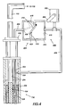
- FIG. 4 is a detailed illustration of the air flow control circuit 400.
- Air flow control circuit 400 automatically directs and regulates the amount of atmospheric air that enters riser pipe 204 and vacuum extraction pipe 206 so well operation can be sustained throughout the various seasonal changes that take place.
- Air flow control circuit 400 includes tube 402 connected in air flow relationship to a first side 408 of check valve assembly 406.
- Check valve assembly 406 includes a housing 416 with a gate 414 hingedly connected to one interior wall 418. Housing 416 has a stop 412 mounted to another interior wall 420 such that gate 414 may either rest against stop 412 in a closed position, or move away from stop 412 to an open position.
- a first opening of tube 402 is placed inside riser pipe 204, so that it may be attached to vacuum extraction pipe 206 through ports 208 at various locations. This enables the vacuum to draw air from air flow control circuit 400 into vacuum extraction pipe 206.
- Tube 404 connects a second side 410 of check valve assembly 406 to extraction well 114 at point 306.
- Point 306 serves as an entry into riser pipe 204.
- Air inlet 302 and valve 304 are connected to tube 404, between check valve assembly 406 and point 306 such that atmospheric air may be directed into check valve assembly 406, and/or into riser pipe 204.
- FIG. 5 is a detailed illustration which shows air flow control circuit 400 attached to extraction well 114.
- One end of tube 402 is placed inside of riser pipe 204 between the inner wall of the riser pipe and the outer wall of vacuum extraction pipe 206.
- gate 414 rests against stop 412 in the closed position.
- a vacuum is applied at the top of vacuum extraction pipe 206, and valve 304 is opened to allow atmospheric air from inlet 302 to enter extraction well 114 at point 306.
- the vacuum inside of extraction well 114, and particularly the resulting horizontal force at point 306, will pull gate 414 toward the well causing it to remain closed.
- check valve assembly 406 will prevent air from passing gate 414, and will therefore stop ambient air from entering vacuum extraction pipe 206 through tube 402. Aspiration air may still be drawn into extraction well 114 through air inlet 302 at point 306.
- the present invention provides a means for automatically supplying, directing and regulating the flow of ambient air to the extraction well, thereby eliminating the need for manual adjustment to maintain well operation, although valve 304 could still be manually adjusted.
- the excess groundwater surrounding the well causes the vacuum inside extraction well 114 to be reduced. This reduced vacuum results in a decrease in the horizontal force being applied at point 306.
- the weakened horizontal force causes gate 414 to open, and allows ambient air to flow into vacuum extraction pipe 206 through tube 402 as needed.
- the flow of ambient air into vacuum extraction pipe 206 will continue until the volume of air within the pipe is large enough to lift the column of effluent to a level at which the vacuum can draw it upward, and apply a vertical force to the effluent stream sufficient to entrain the effluent stream, and lift it from the ground.
Landscapes
- Life Sciences & Earth Sciences (AREA)
- Soil Sciences (AREA)
- Engineering & Computer Science (AREA)
- Environmental & Geological Engineering (AREA)
- Processing Of Solid Wastes (AREA)
- Physical Water Treatments (AREA)
Applications Claiming Priority (2)
| Application Number | Priority Date | Filing Date | Title |
|---|---|---|---|
| US606785 | 1984-05-03 | ||
| US60678596A | 1996-02-27 | 1996-02-27 |
Publications (3)
| Publication Number | Publication Date |
|---|---|
| EP0792700A2 true EP0792700A2 (fr) | 1997-09-03 |
| EP0792700A3 EP0792700A3 (fr) | 1998-05-27 |
| EP0792700B1 EP0792700B1 (fr) | 2002-07-24 |
Family
ID=24429443
Family Applications (1)
| Application Number | Title | Priority Date | Filing Date |
|---|---|---|---|
| EP97301074A Expired - Lifetime EP0792700B1 (fr) | 1996-02-27 | 1997-02-19 | Dispositif et procédés pour éliminer des contaminants |
Country Status (5)
| Country | Link |
|---|---|
| US (1) | US6024868A (fr) |
| EP (1) | EP0792700B1 (fr) |
| JP (1) | JP3971480B2 (fr) |
| BR (1) | BR9701080A (fr) |
| DE (1) | DE69714101T2 (fr) |
Cited By (3)
| Publication number | Priority date | Publication date | Assignee | Title |
|---|---|---|---|---|
| EP0928642A2 (fr) * | 1998-01-08 | 1999-07-14 | Xerox Corporation | Système automatique pour commander l'aspiration d'air |
| FR2809179A1 (fr) * | 2000-05-18 | 2001-11-23 | Ate Antipollution Tech Entpr | Dispositif d'amorcage automatique de cannes de prelevement de fluides |
| WO2014085152A1 (fr) * | 2012-11-30 | 2014-06-05 | Baker Hughes Incorporated | Appareil et procédé pour obtenir des échantillons de fluide de formation |
Families Citing this family (6)
| Publication number | Priority date | Publication date | Assignee | Title |
|---|---|---|---|---|
| US20020162805A1 (en) * | 2001-02-27 | 2002-11-07 | Shenoi Noel A. | Removing contaminants from groundwater |
| US6520259B1 (en) | 2001-10-11 | 2003-02-18 | Jeremy Mathew Rasmussen | Method and apparatus for fluid entrainment |
| US20040231513A1 (en) * | 2002-03-12 | 2004-11-25 | Perkins James A. | System for inline stripping of soil contaminants |
| US7293608B1 (en) | 2004-12-10 | 2007-11-13 | Dudley Clifton M | Liquid well stimulator |
| US20100104369A1 (en) * | 2008-10-23 | 2010-04-29 | Youzhi Chen | Thermal Driven Soil Venting System |
| US9999909B2 (en) * | 2016-04-07 | 2018-06-19 | Edward Augustus Council, III | Soil gas and groundwater remediation system and method |
Citations (3)
| Publication number | Priority date | Publication date | Assignee | Title |
|---|---|---|---|---|
| US3941510A (en) * | 1974-08-09 | 1976-03-02 | Morgan Thomas H | Artificial lift for oil wells |
| EP0304712A2 (fr) * | 1987-08-25 | 1989-03-01 | IEG Industrie-Engineering GmbH | Procédé et dispositif pour retirer des polluants volatilisables du sol |
| US5358357A (en) * | 1993-04-30 | 1994-10-25 | Xerox Corporation | Process and apparatus for high vacuum groundwater extraction |
Family Cites Families (10)
| Publication number | Priority date | Publication date | Assignee | Title |
|---|---|---|---|---|
| US4323122A (en) * | 1980-06-02 | 1982-04-06 | Knopik Dwayne L | Process for recovering organic liquids from underground areas |
| US4844797A (en) * | 1988-03-22 | 1989-07-04 | S&Me, Incorporated | Vacuum extraction system |
| US5147530A (en) * | 1988-11-10 | 1992-09-15 | Water Soft Inc. | Well water removal and treatment system |
| US5197541A (en) * | 1989-09-27 | 1993-03-30 | Xerox Corporation | Apparatus for two phase vacuum extraction of soil contaminants |
| US5050676A (en) * | 1989-09-27 | 1991-09-24 | Xerox Corporation | Process for two phase vacuum extraction of soil contaminants |
| DE4021814A1 (de) * | 1990-05-23 | 1991-11-28 | Ieg Ind Engineering Gmbh | Anordnung zur gasbehandlung von verunreinigtem erdreich |
| US5172764A (en) * | 1991-02-07 | 1992-12-22 | Xerox Corporation | Process and apparatus for groundwater extraction using a high vacuum process |
| US5373897A (en) * | 1993-04-29 | 1994-12-20 | Skarvan; Richard | Underground fluid recovery device |
| US5464309A (en) * | 1993-04-30 | 1995-11-07 | Xerox Corporation | Dual wall multi-extraction tube recovery well |
| US5441365A (en) * | 1994-04-29 | 1995-08-15 | Xerox Corporation | Apparatus and process for treating contaminated soil gases and liquids |
-
1997
- 1997-02-19 DE DE69714101T patent/DE69714101T2/de not_active Expired - Lifetime
- 1997-02-19 EP EP97301074A patent/EP0792700B1/fr not_active Expired - Lifetime
- 1997-02-20 JP JP03668897A patent/JP3971480B2/ja not_active Expired - Fee Related
- 1997-02-26 BR BR9701080A patent/BR9701080A/pt not_active Application Discontinuation
- 1997-08-28 US US08/919,966 patent/US6024868A/en not_active Expired - Lifetime
Patent Citations (3)
| Publication number | Priority date | Publication date | Assignee | Title |
|---|---|---|---|---|
| US3941510A (en) * | 1974-08-09 | 1976-03-02 | Morgan Thomas H | Artificial lift for oil wells |
| EP0304712A2 (fr) * | 1987-08-25 | 1989-03-01 | IEG Industrie-Engineering GmbH | Procédé et dispositif pour retirer des polluants volatilisables du sol |
| US5358357A (en) * | 1993-04-30 | 1994-10-25 | Xerox Corporation | Process and apparatus for high vacuum groundwater extraction |
Cited By (4)
| Publication number | Priority date | Publication date | Assignee | Title |
|---|---|---|---|---|
| EP0928642A2 (fr) * | 1998-01-08 | 1999-07-14 | Xerox Corporation | Système automatique pour commander l'aspiration d'air |
| EP0928642A3 (fr) * | 1998-01-08 | 2000-03-29 | Xerox Corporation | Système automatique pour commander l'aspiration d'air |
| FR2809179A1 (fr) * | 2000-05-18 | 2001-11-23 | Ate Antipollution Tech Entpr | Dispositif d'amorcage automatique de cannes de prelevement de fluides |
| WO2014085152A1 (fr) * | 2012-11-30 | 2014-06-05 | Baker Hughes Incorporated | Appareil et procédé pour obtenir des échantillons de fluide de formation |
Also Published As
| Publication number | Publication date |
|---|---|
| EP0792700A3 (fr) | 1998-05-27 |
| JPH09225448A (ja) | 1997-09-02 |
| EP0792700B1 (fr) | 2002-07-24 |
| JP3971480B2 (ja) | 2007-09-05 |
| DE69714101D1 (de) | 2002-08-29 |
| BR9701080A (pt) | 1998-07-21 |
| US6024868A (en) | 2000-02-15 |
| DE69714101T2 (de) | 2002-11-28 |
Similar Documents
| Publication | Publication Date | Title |
|---|---|---|
| EP0707899B1 (fr) | Procédé et dispositif pour éliminer des contaminants d'une zone de sol contaminée | |
| CA2053446C (fr) | Procede et appareil d'extraction d'eau souterraine par vide pousse | |
| EP0622131B1 (fr) | Procédé pour l'extraction des eaux souterraines sous vide élevé | |
| JP2852117B2 (ja) | 土壌汚染物質の二相真空抽出方法及び装置 | |
| EP0747142B1 (fr) | Système vertical d'isolation pour l'extraction par le vide de deux phases de contaminants du sol et de l'eau souterraine | |
| US5076360A (en) | Priming methods for vacuum extraction wells | |
| US5197541A (en) | Apparatus for two phase vacuum extraction of soil contaminants | |
| US5173092A (en) | Hydrocarbon removal system | |
| US5441365A (en) | Apparatus and process for treating contaminated soil gases and liquids | |
| US5655852A (en) | High vacuum extraction of soil contaminants along preferential flow paths | |
| EP0792700B1 (fr) | Dispositif et procédés pour éliminer des contaminants | |
| US5439594A (en) | Method for subsurface vapor extraction | |
| US6146104A (en) | Groundwater recovery system incorporating a combination of pressure and vacuum to accomplish removal of groundwater fluids from a downhole pump | |
| EP0928642B1 (fr) | Système automatique pour commander l'aspiration d'air | |
| US6305473B1 (en) | Vacuum extraction apparatus and process | |
| JPH07284753A (ja) | 地下汚染物質の除去方法および地下汚染物質の除去装置 | |
| US5529121A (en) | Process for recovery and separation of volatile and non-volatile and non-volatile compounds | |
| EP0911071B1 (fr) | Dispositif pour éliminer des contaminants liquides |
Legal Events
| Date | Code | Title | Description |
|---|---|---|---|
| PUAI | Public reference made under article 153(3) epc to a published international application that has entered the european phase |
Free format text: ORIGINAL CODE: 0009012 |
|
| AK | Designated contracting states |
Kind code of ref document: A2 Designated state(s): DE FR GB |
|
| PUAL | Search report despatched |
Free format text: ORIGINAL CODE: 0009013 |
|
| AK | Designated contracting states |
Kind code of ref document: A3 Designated state(s): DE FR GB |
|
| 17P | Request for examination filed |
Effective date: 19981127 |
|
| 17Q | First examination report despatched |
Effective date: 19991207 |
|
| GRAG | Despatch of communication of intention to grant |
Free format text: ORIGINAL CODE: EPIDOS AGRA |
|
| GRAG | Despatch of communication of intention to grant |
Free format text: ORIGINAL CODE: EPIDOS AGRA |
|
| GRAH | Despatch of communication of intention to grant a patent |
Free format text: ORIGINAL CODE: EPIDOS IGRA |
|
| GRAH | Despatch of communication of intention to grant a patent |
Free format text: ORIGINAL CODE: EPIDOS IGRA |
|
| GRAA | (expected) grant |
Free format text: ORIGINAL CODE: 0009210 |
|
| AK | Designated contracting states |
Kind code of ref document: B1 Designated state(s): DE FR GB |
|
| REG | Reference to a national code |
Ref country code: GB Ref legal event code: FG4D |
|
| REF | Corresponds to: |
Ref document number: 69714101 Country of ref document: DE Date of ref document: 20020829 |
|
| ET | Fr: translation filed | ||
| PLBE | No opposition filed within time limit |
Free format text: ORIGINAL CODE: 0009261 |
|
| STAA | Information on the status of an ep patent application or granted ep patent |
Free format text: STATUS: NO OPPOSITION FILED WITHIN TIME LIMIT |
|
| 26N | No opposition filed |
Effective date: 20030425 |
|
| PGFP | Annual fee paid to national office [announced via postgrant information from national office to epo] |
Ref country code: GB Payment date: 20130129 Year of fee payment: 17 Ref country code: DE Payment date: 20130124 Year of fee payment: 17 Ref country code: FR Payment date: 20130408 Year of fee payment: 17 |
|
| REG | Reference to a national code |
Ref country code: DE Ref legal event code: R119 Ref document number: 69714101 Country of ref document: DE |
|
| GBPC | Gb: european patent ceased through non-payment of renewal fee |
Effective date: 20140219 |
|
| REG | Reference to a national code |
Ref country code: FR Ref legal event code: ST Effective date: 20141031 |
|
| REG | Reference to a national code |
Ref country code: DE Ref legal event code: R119 Ref document number: 69714101 Country of ref document: DE Effective date: 20140902 |
|
| PG25 | Lapsed in a contracting state [announced via postgrant information from national office to epo] |
Ref country code: GB Free format text: LAPSE BECAUSE OF NON-PAYMENT OF DUE FEES Effective date: 20140219 Ref country code: FR Free format text: LAPSE BECAUSE OF NON-PAYMENT OF DUE FEES Effective date: 20140228 Ref country code: DE Free format text: LAPSE BECAUSE OF NON-PAYMENT OF DUE FEES Effective date: 20140902 |