EP0791926A2 - Structure de couvercle de cassette à disque - Google Patents
Structure de couvercle de cassette à disque Download PDFInfo
- Publication number
- EP0791926A2 EP0791926A2 EP97103001A EP97103001A EP0791926A2 EP 0791926 A2 EP0791926 A2 EP 0791926A2 EP 97103001 A EP97103001 A EP 97103001A EP 97103001 A EP97103001 A EP 97103001A EP 0791926 A2 EP0791926 A2 EP 0791926A2
- Authority
- EP
- European Patent Office
- Prior art keywords
- lid
- cartridge casing
- cartridge
- access opening
- disc
- Prior art date
- Legal status (The legal status is an assumption and is not a legal conclusion. Google has not performed a legal analysis and makes no representation as to the accuracy of the status listed.)
- Granted
Links
- 230000001105 regulatory effect Effects 0.000 claims abstract description 5
- 230000003287 optical effect Effects 0.000 description 31
- 238000003780 insertion Methods 0.000 description 6
- 230000037431 insertion Effects 0.000 description 6
- 238000013461 design Methods 0.000 description 3
- 238000000465 moulding Methods 0.000 description 3
- 238000012986 modification Methods 0.000 description 2
- 230000004048 modification Effects 0.000 description 2
- 230000002093 peripheral effect Effects 0.000 description 2
- 230000015572 biosynthetic process Effects 0.000 description 1
- 238000004891 communication Methods 0.000 description 1
- 238000010276 construction Methods 0.000 description 1
- 238000004519 manufacturing process Methods 0.000 description 1
- 239000000463 material Substances 0.000 description 1
- 238000000034 method Methods 0.000 description 1
- 230000002787 reinforcement Effects 0.000 description 1
- 230000000717 retained effect Effects 0.000 description 1
- 229920003002 synthetic resin Polymers 0.000 description 1
- 239000000057 synthetic resin Substances 0.000 description 1
Images


Classifications
-
- G—PHYSICS
- G11—INFORMATION STORAGE
- G11B—INFORMATION STORAGE BASED ON RELATIVE MOVEMENT BETWEEN RECORD CARRIER AND TRANSDUCER
- G11B23/00—Record carriers not specific to the method of recording or reproducing; Accessories, e.g. containers, specially adapted for co-operation with the recording or reproducing apparatus ; Intermediate mediums; Apparatus or processes specially adapted for their manufacture
- G11B23/02—Containers; Storing means both adapted to cooperate with the recording or reproducing means
- G11B23/03—Containers for flat record carriers
- G11B23/0301—Details
- G11B23/0317—Containers with interchangeable record carriers
Definitions
- the present invention generally relates to a disc cartridge of a generally rectangular configuration for removably accommodating a disc-shaped optical or magnetooptical recording medium and, more particularly, to a lid structure for the disc cartridge for selectively opening and closing the access opening leading into the interior of the disc cartridge for removal or replacement of the optical recording medium.
- the disc cartridge of the type referred to above is disclosed in, for example, the Japanese Laid-open Patent Publication No. 5-243626, published in 1994.
- the disc cartridge comprises a generally rectangular flattened casing having an access opening defined at a rear end thereof so as to extend over the entire width thereof.
- This known disc cartridge also includes a lid for selectively opening and closing the access opening to allow the disc-shaped recording medium, for example, the optical disc, to be removed from and inserted into the interior of the casing, respectively.
- the lid has a flange that can be received within the access opening in the casing when it is held in position to close the access opening.
- This lid is pivoted at one end to one corner region at the rear end of the casing so that it can be swung about 180° to open the access opening.
- the cartridge casing has a width slightly greater than the outer diameter of the optical disc and, therefore, if the detent recesses are formed in opposite side walls of the cartridge casing, the detent recesses would leave an internal space therebetween which is narrower than the outer diameter of the optical disc. Accordingly, where the detent recesses are to be formed, the cartridge casing must have an increased width in order for the optical disc to be smoothly removed from or inserted into the cartridge casing. Thus, formation of the detent recesses in the cartridge casing inevitably results in increase in size of the disc cartridge.
- the increase in size of the disc cartridge may be avoided if a wall element defining each detent recess in the respective side wall of the cartridge casing is formed with a slit that is so sized and so shaped as to allow opposite outer peripheral portions of the optical disc to pass through the associated slits during removal or insertion of the optical disc from or into the cartridge casing.
- the use of the slits in the wall elements defining the respective detent recesses in turn necessitates the lid to be so shaped and so configured as to have, in addition to the capability of selectively opening and closing the access opening, an extra capability of selectively opening and closing the slits to thereby avoid any possible ingress of foreign matter into the cartridge casing.
- a space between the optical disc and the access opening is necessarily occupied by the lid having a thickness generally equal to the space between top and bottom panels forming the cartridge casing.
- the lid having such an increased wall thickness is susceptible to deformation during molding thereof and, for example, the accuracy with which a partially arcuate regulating surface used to restrict an arbitrary motion or play of the optical disc within the cartridge casing is formed tends to be lowered.
- an increased amount of synthetic resin is needed to form the lid, accompanied by increase in manufacturing cost and weight.
- the present invention has accordingly an essential object to provide an improved disc cartridge of a type having positioning recesses defined in the vicinity of the access opening, which is compact in size and effective to allow the optical disc to be easily and smoothly removed from or inserted into the cartridge casing and which is dust-tight when the lid is in position to close the access opening.
- Another important object of the present invention is to provide an improved disc cartridge of the type referred to above, wherein both the volume and the weight of the lid are reduced to allow the lid to be manufactured accurately and at reduced cost.
- a further important object of the present invention is to provide an improved disc cartridge of the type referred to above, wherein the lid has a minimized stroke of pivotal movement between opened and closed position to allow the optical disc to be conveniently removed from or inserted into the disc casing.
- the disc cartridge comprises a cartridge casing for freely rotatably accommodating a disc-shaped recording medium, which is provided with positioning recesses defined in respective portions of the right and left sides of the cartridge casing adjacent the rear end thereof.
- a generally U-shaped access opening is defined in the rear end of the cartridge casing and respective portions of the left and right sides thereof including the associated recesses.
- a lid assembly for selectively opening and closing the access opening is pivotally supported by the cartridge casing.
- the lid assembly includes a lid body adapted to protrude into the cartridge casing so as to occupy a space between the recording medium within the cartridge casing and the access opening.
- the lid body includes a regulating surface for restricting a play of the recording medium within the cartridge casing and left and right cutouts defined therein in a manner alignable with the left and right recesses, respectively.
- a thin-walled cavity for reducing the volume and weight of the lid assembly being formed so as to occupy a major portion of surface walls of the lid body while opening at at least one of upper and lower surface walls.
- the lid assembly comprises a first lid including the lid body and having one of the left and right cutouts and a second lid including the lid body and having the other of the left and right cutouts.
- a lock mechanism is employed in the vicinity of neighboring ends of the first and second lids for engagement to retain the first and second lids in a closed position.
- the first lid includes the lid body for closing a major portal area of the access opening and is supported by the cartridge casing for pivotal movement about a first pivot pin disposed frontwardly of one of the cutouts
- the second lid is supported by the cartridge casing for pivotal movement about a second pivot pin, disposed frontwardly of the other of the cutouts, in a direction substantially opposite to the first lid.
- the lock mechanism includes a lock pawl formed in a rear end of the second lid so as to protrude outwardly therefrom and a lock recess defined in an inner surface of a free end of the first lid remote from the first pivot pin.
- the first lid includes the lid body for closing a major portal area of the access opening and is supported by the cartridge casing for sliding along the major portal area of the access opening, wherein the second lid is supported by the cartridge casing for pivotal movement about a pivot pin, disposed frontwardly of the adjacent cutout.
- the lock mechanism includes a first engagement defined in one end of the first lid adjacent the second lid and a second engagement defined in a rear end of the second lid.
- the generally U-shaped access opening is defined in the cartridge casing so as to occupy the rear surface of the cartridge casing and the rear portions of the left and right sides of the cartridge casing including the left and right positioning recesses. Since this access opening is adapted to be closed by the lid assembly occupying a part of the contour of the cartridge casing, selective insertion and removal of the recording medium into and from the cartridge casing can easily be accomplished simply by opening the lid assembly. In addition, respective portions of the walls confronting the left and right recesses are opened, the cartridge casing need not have an increased size.
- the lid assembly With the lid assembly held in the closed position, the lid assembly closes the access opening to thereby avoid any possible ingress of foreign matter into the cartridge casing.
- the provision of the thin-walled cavity in the lid body which occupies a substantial portion of the lid assembly is effective to reduce the volume and weight of the lid assembly in a quantity corresponding to those of the thin-walled cavity. Any possible deformation during molding can also be avoided.
- the stroke of movement of each of the first and second lids can be reduced as compared with that in the prior art disc cartridge, to thereby facilitate an easy insertion and removal of the recording medium into and from the disc cartridge.
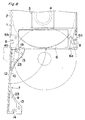
- a disc-shaped optical or magnetooptical recording medium is shown in the form of, for example, an optical disc 1 having first and second major surfaces opposite to each other with audio and/or video signals recorded on each major surface thereof.
- This optical disc 1 is freely rotatably accommodated within a disc cartridge made of a moldable plastic material and including a generally rectangular flattened cartridge casing 2.
- the cartridge casing 2 is made up of top and bottom panels 2a and 2b joined together by means of left and right side walls and a front side wall, with an access opening 6 defined in opposition to the front side wall for selective removal or insertion of the optical disc 1 from or into the interior of the cartridge casing.
- the disc cartridge has generally rectangular access windows 4 defined respectively in the top and bottom panels 2a and 2b at a location intermediate of the width of the disc cartridge for the access of read/write heads (not shown) to the associated major surfaces of the optical disc 1.
- the access windows 4 are normally closed by a slide shutter 3 that is locked at a closed position by a suitable lock mechanism (not shown) when the disc cartridge is not loaded in an information recording and/or reproducing machine.
- the access opening 6 is adapted to be selectively opened and closed by a cover assembly 7 that is pivotally supported by the cartridge casing 2.
- Left and right positioning recesses 8 are provided on respective sides of the cartridge casing 1 adjacent the rear end thereof.
- the access opening 6 is made up of a major portal area 6a of a size sufficient to occupy an entire width of the rear end of the cartridge casing 1 and left and right side portal areas 6b open at respective rear ends of left and right side walls of the cartridge casing 2 which encompass the associated positioning recesses 8.
- the access opening 6, when viewed from above as shown in Figs. 1 and 2, represents a generally U-shaped configuration extending from a rear end of one side wall of the cartridge casing 2 to a rear end of the opposite side wall of the cartridge casing 2 after having traversed the rear end of the cartridge casing 2.
- the cover assembly 7 is of a two-piece design including a first lid 7A and a second lid 7B. As shown in Fig. 1, each lid 7A and 7B is provided with a lid body 9 protruding into the cartridge casing 2 so as to occupy a space between the optical disc 1 and the access opening.
- the lid body 9 of each of the first and second lids 7A and 7B is formed with a partially arcuate regulating surface 10 for restricting an arbitrary motion or play of the optical disc 1 within the cartridge casing 2.
- the lid body 9 of the first lid 7A includes a rear wall 12 for closing the major portal area 6a of the access opening 6 and a generally trapezoidal corner wall 13 for filling up a rear left corner region of the cartridge casing 2 and has a generally U-shaped cutout 14, similar in shape to the left positioning recess 8, defined in a side wall segment of the corner wall 13 in alignment with the associated positioning recess 8.
- the corner wall 13 has a front wall segment formed with a bearing lug 15 through which a pivot pin 16 integral with an inner surface of the bottom panel 2b extends so as to allow the first lid 7A to pivot thereabout between opened and closed positions spaced from each other an angle of 90° or more about the pivot pin 16.
- the first lid 7A is, when in the closed position as shown by the solid line in Fig. 1, held in position to close the major portal area 6a and the left side portal area 6b simultaneously, but is, when in the opened position substantially as shown by the double-dotted phantom line in Fig. 2, held in position to open the major portal area 6a and the left side portal area 6b simultaneously.
- the position where the pivot pin 16 is formed on the bottom panel 2b of the cartridge casing 2 is preferably chosen as to be as close to the left side of the cartridge casing 2 as possible.
- the lid body 9 of the second lid 7B includes a generally trapezoidal corner wall 18 for filling up a rear right corner region of the cartridge casing 2 and has a generally U-shaped cutout 19, similar in shape to the right positioning recess 8, defined in a side wall segment of the corner wall 18 in alignment with the associated positioning recess 8.
- the corner wall 18 has a front wall segment formed with a bearing lug 20 through which a pivot pin 21 integral with the inner surface of the bottom panel 2b extends so as to allow the second lid 7B to pivot thereabout between opened and closed positions spaced from each other an angle of 90° or more about the pivot pins 21. Accordingly, the second lid 7B is, when in the closed position as shown by the solid line in Fig.
- the pivot pin 21 is preferably positioned as close to the right side of the cartridge casing 2 as possible.
- a thin-walled cavity 23 is defined in each of the first and second lids 7A and 7B to thereby render the respective corner wall 13 or 18 to represent a generally frame structure.
- the thin-walled cavity 23 defined in the first lid 7A extends completely across the first lid 7A in a direction substantially perpendicular to any of the top and bottom panels 2a and 2b while occupying a major portion of the corner wall 13 and is traversed by a reinforcement rib 24 formed in the corner wall 13 so as to divide the thin-walled cavity 23 into two segments.
- a front lower surface region of the rear wall 12 which confronts the thin-walled cavity 23 is formed with a generally arcuate drawing pawl 25 which is engageable with a guide pin 26 integral with the bottom panel 2b, when the first lid 7A is pivoted towards the closed position, to guide the first lid 7A as a whole inwardly into the access opening 6 (See Fig. 4).
- the thin-walled cavity 23 defined in the second lid 7B extends completely across the second lid 7B in a direction substantially perpendicular to any of the top and bottom panels 2a and 2b while occupying a major portion of the corner wall 18.
- a front lower surface region of a rear wall of the corner wall 18 which confronts the thin-walled cavity 23 is formed with a generally arcuate drawing pawl 27 which is engageable with a guide pin 28 integral with the bottom panel 2b, when the second lid 7B is pivoted towards the closed position, to guide the second lid 7B as a whole inwardly into the right portal area 6b.
- Respective portions of the top and bottom panels 2a and 2b which are aligned with the thin-walled cavities 23 in the first and second lids 7A and 7B then held in the closed position are formed with positioning holes 29 through which associated positioning pins installed on a player or disc drive are engaged when the disc cartridge is loaded in the player or disc drive.
- the thin-walled cavities 23 defined in the first and second lids 7A and 7B can be advantageously utilized to accommodate the positioning pins then extending through the positioning holes 29 as shown in Fig. 1.
- a lock mechanism 31 is employed and disposed between the first and second lids 7A and 7B.
- the lock mechanism 31 includes a generally wedge-shaped lock pawl 32 formed in the second lid 7B at a location on one side opposite to the U-shaped cutout 19 so as to protrude outwardly therefrom, and a lock recess 33 defined in an inner surface of a free end of the first lid 7A remote from the bearing lug 15, that is, an inner surface of a right end of the rear wall 12 of the first lid 7A.
- the lock pawl 32 is engageable with an inclined step 34 defined deep in the lock recess 33 to thereby prevent the first lid 7A from being freely pivoted towards the opened position about the pivot pin 16.
- the lock pawl 32 has an upper surface formed with a knob 35 protruding outwardly through an aperture 36, defined in the top panel 2a, so as to terminate in flush with an outer surface of the top panel 2a as shown in Fig. 5.
- a portion of the outer surface of the top panel 2a adjacent the aperture 36 is formed with a shallow, finger-engaging groove 37 to accommodate a finger that is placed on the knob 35 when the first and second lids 7A and 7B are desired to be opened.
- the knob 35 has to be pulled outwardly against an engaging force of the lock paw 32 to thereby allow the second and first lids 7B and 7A to successively swing to open the access opening 6.
- the first and second lids 7A and 7B so opened can be closed by following a process substantially reverse to that described above, with the first and second lids 7A and 7B consequently brought to the closed position to thereby avoid any possible ingress of foreign matter into the disc cartridge through the positioning recesses 8.
- cover assembly 7 has been shown and described as made up of the pivotally supported first and second lids 7A and 7B, the cover assembly employed in a second embodiment shown in Figs. 6A, 6B and 7 makes use of a slidable lid and a pivotable lid which will now be described in detail.
- the first or slide lid 7A is supported by the cartridge casing 2 for sliding movement between opened and closed positions in a direction along the plane of the access opening 6, that is, in a direction lengthwise thereof. More specifically, as best shown in Fig. 7, the rear wall 12 of the lid body 9 of the slide lid 7A has top and bottom longitudinal surfaces formed with respective guide ribs 29 protruding outwardly therefrom.
- This slide lid 7A is supported by the cartridge casing 2 with the guide ribs 29 slidingly received in associated guide grooves 40 that are defined in the inner surfaces of the top and bottom panels 2a and 2b.
- a slide operating knob 41 accessible to the finger of the user is formed on a portion of the rear surface of the rear wall 12 adjacent the second or pivotable lid 7B.
- the pivotable lid 7B is supported for pivotal movement between the opened and closed position about a pivot pin 42 extending between the top and bottom panels 2a and 2b at a location adjacent a front portion of the right positioning recess 19.
- the lock mechanism 31 employed in the second embodiment includes a first engagement 43 in the form of an engagement recess defined in an inner surface of a right end of the rear wall 12 and a second engagement 44 in the form of an engagement projection engageable with the first engagement 43 and formed in a rear end of a corner wall 41 that is positioned rearwardly of the positioning recess 19.
- This lock mechanism 31 is so shaped and so configured that when and so long as the slide and pivotable lids 7A and 7B are held in the closed position as shown in Fig. 6A, the first and second engagements 43 and 44 can be engaged with each other, but when the slide lid 7A is forcibly moved in a leftward direction, as viewed in Figs.
- the first and second engagements 43 and 44 can be disengaged from each other to open the major portal area 6a and the left side portal area 6b.
- the slide lid 7A can be closed when the latter is moved in a rightward direction as viewed in Figs. 6A and 6B and, on the other hand, when the pivotable lid 7B is pushed towards the major portal area 6a, the second engagement 44 integral with the pivotable lid 7B can be engaged with the first engagement 43 integral with the slide lid 7A to lock the slide and pivotable lids 7A and 7B in the closed position.
- the lid assembly 7 has been of the two-piece design including the first and second lids 7A and 7B.
- a single lid is employed for the lid assembly 7.
- the lid 7 comprises the lid body 9 including the rear wall 12 for closing the major portal area 6a and the left and right corner walls 13 formed integrally with left and right ends of the rear wall 12 so as to protrude towards the cartridge casing 2.
- the lid body 9 is supported for pivotal movement between opened and closed positions about a pivot pin 45 journalled to rear left and right corners of the cartridge casing 2.
- the left and right corner walls 13 are formed with respective cutouts 45 which are, when and so long as the lid body 9 is in the closed position, aligned with and in communication with the positioning recesses 8, respectively.
- thin-walled cavities 23 are defined in the left and right corner walls 13.
- the lid assembly employed in the embodiment shown in Fig. 8 functions in a manner substantially similar to that employed in the first embodiment of the present invention. Specifically, when the lid body 9 is pivoted from the closed position approximately 180° about the pivot pin 45, the access opening 6 can be opened.
- each thin-walled cavity 23 although shown as extending completely across the associated lid in a direction substantially perpendicular to any of the top and bottom panels, may have a bottom defined by either the top panel or the bottom panel of the cartridge casing. Alternatively, it may be in the form of a confined chamber.
- the first and second lids 7A and 7B may be divided generally at a center of the rear of the casing and may be retained in the closed position by means of the lock mechanism disposed between the first and second lids 7A and 7B.
- the first lid 7A may be formed including one of the top and bottom panels of the cartridge casing 2, in which case the first lid 7A may be supported for pivotal movement in a vertical direction relative to the cartridge casing 2.
- the bearing lugs 15 and 20 employed in the first embodiment of the present invention may be formed to have the same thickness as the corner walls 13 and 18.
- the generally U-shaped access opening 6 is defined in the cartridge casing 2 so as to occupy the rear surface of the cartridge casing 2 and the rear portions of the left and right sides of the cartridge casing 2 including the left and right positioning recesses 8, in combination with the use of the lid body 9 which protrudes into the cartridge casing 2 so that the access opening 6 can be assuredly closed by the lid assembly 7.
- the disc 1 an easily be removed from or inserted into the cartridge casing 2 with no need to render the cartridge casing 2 bulky in size and, moreover, any possible ingress of foreign matter into the cartridge casing 2 through the positioning recesses 8 can be avoided, when and so long as the lid assembly is closed, to thereby eliminate the problem associated with recording and/or reading errors which would otherwise occur as a result of adherence of foreign matter on the optical disc 1.
- the lid body 9 which occupies a major portion of the lid assembly 7 is formed with the thin-walled cavity 23, the volume and weight of the lid assembly 7 can be reduced considerably as compared with those of the conventional lid assembly, eliminating the possibility that the lid assembly may be deformed during molding thereof.
- the lid assembly 7 is made up of the first and second lids 7A and 7B and the access opening 6 can be opened by opening the first and second lids 7A and 7B, the stroke of movement of each of the first and second lids 7A and 7B can be reduced as compared with that in the prior art disc cartridge, to thereby facilitate an easy insertion and removal of the optical disc 1 into and from the disc cartridge.
- the lid assembly can be locked closed by means of the lock mechanism 31 disposed between the first and second lids 7A and 7B, the possibility that the lid assembly 7 is accidentally opened when, for example, the weight of the optical disc 1 acts on the first lid 7A during the handling of the disc cartridge can advantageously be avoided to thereby avoid the possibility that the optical disc 1 may be damaged when the disc cartridge is inadvertently fallen onto the ground.
Landscapes
- Packaging For Recording Disks (AREA)
Applications Claiming Priority (3)
| Application Number | Priority Date | Filing Date | Title |
|---|---|---|---|
| JP65492/96 | 1996-02-26 | ||
| JP06549296A JP3516089B2 (ja) | 1996-02-26 | 1996-02-26 | ディスクカートリッジ |
| JP6549296 | 1996-02-26 |
Publications (3)
| Publication Number | Publication Date |
|---|---|
| EP0791926A2 true EP0791926A2 (fr) | 1997-08-27 |
| EP0791926A3 EP0791926A3 (fr) | 1997-09-24 |
| EP0791926B1 EP0791926B1 (fr) | 2003-05-07 |
Family
ID=13288657
Family Applications (1)
| Application Number | Title | Priority Date | Filing Date |
|---|---|---|---|
| EP97103001A Expired - Lifetime EP0791926B1 (fr) | 1996-02-26 | 1997-02-25 | Structure de couvercle pour cassette à disque |
Country Status (4)
| Country | Link |
|---|---|
| US (1) | US5910941A (fr) |
| EP (1) | EP0791926B1 (fr) |
| JP (1) | JP3516089B2 (fr) |
| DE (1) | DE69721609T2 (fr) |
Families Citing this family (4)
| Publication number | Priority date | Publication date | Assignee | Title |
|---|---|---|---|---|
| JP3594314B2 (ja) * | 1995-09-21 | 2004-11-24 | 松下電器産業株式会社 | ディスク取り出し可能なディスクカートリッジ |
| TW385433B (en) * | 1996-10-28 | 2000-03-21 | Dainippon Printing Co Ltd | A cartridge case for a disk-shaped recording medium and a disk cartridge |
| SG94718A1 (en) * | 1998-05-23 | 2003-03-18 | Samsung Electronics Co Ltd | Cartridge for an information recording medium |
| ES2194613B1 (es) * | 2002-05-02 | 2005-03-16 | Leunamme Engineering S.L. | Funda para apilamiento y extraccion de discos. |
Citations (5)
| Publication number | Priority date | Publication date | Assignee | Title |
|---|---|---|---|---|
| US4455642A (en) * | 1980-10-09 | 1984-06-19 | Victor Company Of Japan, Ltd. | Case for accommodating a rotary recording medium |
| EP0421775A2 (fr) * | 1989-10-06 | 1991-04-10 | Sony Corporation | Cassette à disque |
| GB2272990A (en) * | 1992-11-30 | 1994-06-01 | Hitachi Maxell | Disk cartridge |
| EP0617425A2 (fr) * | 1993-03-23 | 1994-09-28 | Matsushita Electric Industrial Co., Ltd. | Adapteur de cassette et cassette pouvant être reçue dans l'adaption |
| EP0692788A2 (fr) * | 1994-07-14 | 1996-01-17 | Nomai S.A. | Cassette auto-nettoyante amovible à disque dur à haute capacité |
Family Cites Families (2)
| Publication number | Priority date | Publication date | Assignee | Title |
|---|---|---|---|---|
| NL8800820A (nl) * | 1988-03-31 | 1989-10-16 | Philips Nv | Cassette. |
| JPH0268378U (fr) * | 1988-11-11 | 1990-05-23 |
-
1996
- 1996-02-26 JP JP06549296A patent/JP3516089B2/ja not_active Expired - Fee Related
-
1997
- 1997-02-25 EP EP97103001A patent/EP0791926B1/fr not_active Expired - Lifetime
- 1997-02-25 DE DE69721609T patent/DE69721609T2/de not_active Expired - Fee Related
- 1997-02-26 US US08/806,321 patent/US5910941A/en not_active Expired - Fee Related
Patent Citations (5)
| Publication number | Priority date | Publication date | Assignee | Title |
|---|---|---|---|---|
| US4455642A (en) * | 1980-10-09 | 1984-06-19 | Victor Company Of Japan, Ltd. | Case for accommodating a rotary recording medium |
| EP0421775A2 (fr) * | 1989-10-06 | 1991-04-10 | Sony Corporation | Cassette à disque |
| GB2272990A (en) * | 1992-11-30 | 1994-06-01 | Hitachi Maxell | Disk cartridge |
| EP0617425A2 (fr) * | 1993-03-23 | 1994-09-28 | Matsushita Electric Industrial Co., Ltd. | Adapteur de cassette et cassette pouvant être reçue dans l'adaption |
| EP0692788A2 (fr) * | 1994-07-14 | 1996-01-17 | Nomai S.A. | Cassette auto-nettoyante amovible à disque dur à haute capacité |
Also Published As
| Publication number | Publication date |
|---|---|
| JP3516089B2 (ja) | 2004-04-05 |
| EP0791926A3 (fr) | 1997-09-24 |
| EP0791926B1 (fr) | 2003-05-07 |
| DE69721609D1 (de) | 2003-06-12 |
| JPH09231711A (ja) | 1997-09-05 |
| US5910941A (en) | 1999-06-08 |
| DE69721609T2 (de) | 2004-03-25 |
Similar Documents
| Publication | Publication Date | Title |
|---|---|---|
| EP0094087B1 (fr) | Cassette à bande d'enregistrement | |
| CA1196094A (fr) | Cassette de bande | |
| EP0137965A2 (fr) | Cartouche pour disque | |
| EP0421775B1 (fr) | Cassette à disque | |
| JP3710410B2 (ja) | 記録テープカートリッジ | |
| EP0929070A2 (fr) | Cassette à disque | |
| EP0791926B1 (fr) | Structure de couvercle pour cassette à disque | |
| KR20010082025A (ko) | 디스크 카트리지 | |
| US5504644A (en) | Recording/erasing prevention device | |
| EP1001422B1 (fr) | Cassette à disque | |
| JPH09213043A (ja) | ディスクカートリッジ | |
| US5279476A (en) | Tape cassette lid having projection for preventing tape pinching | |
| US5023740A (en) | Tape cassette having tape protecting covers | |
| US5899330A (en) | Encasing mechanism for a cassette enclosing a magnetic record medium | |
| US5689393A (en) | Magnetic disk cartridge having an opening for a magnetic head on a side thereof | |
| US5566037A (en) | Cassette tape player compatible with cassette tapes of different formats | |
| US5367421A (en) | Cartridge for a recording/reproducing medium having a transparent or semi-transparent cover member | |
| US7047546B2 (en) | Disc cartridge | |
| KR100313728B1 (ko) | 테이프카세트 | |
| JP2596489Y2 (ja) | カートリッジ | |
| JP3713861B2 (ja) | ディスクカートリッジ用の収納ケース | |
| JP2654423B2 (ja) | ディスクカートリッジ | |
| JPH0447822Y2 (fr) | ||
| JPH0510301Y2 (fr) | ||
| JPH0356930Y2 (fr) |
Legal Events
| Date | Code | Title | Description |
|---|---|---|---|
| PUAI | Public reference made under article 153(3) epc to a published international application that has entered the european phase |
Free format text: ORIGINAL CODE: 0009012 |
|
| PUAL | Search report despatched |
Free format text: ORIGINAL CODE: 0009013 |
|
| 17P | Request for examination filed |
Effective date: 19970225 |
|
| AK | Designated contracting states |
Kind code of ref document: A2 Designated state(s): DE FR GB |
|
| AK | Designated contracting states |
Kind code of ref document: A3 Designated state(s): DE FR GB |
|
| 17Q | First examination report despatched |
Effective date: 20011108 |
|
| GRAG | Despatch of communication of intention to grant |
Free format text: ORIGINAL CODE: EPIDOS AGRA |
|
| RTI1 | Title (correction) |
Free format text: LID STRUCTURE FOR DISC CARTRIDGE |
|
| GRAG | Despatch of communication of intention to grant |
Free format text: ORIGINAL CODE: EPIDOS AGRA |
|
| GRAH | Despatch of communication of intention to grant a patent |
Free format text: ORIGINAL CODE: EPIDOS IGRA |
|
| GRAH | Despatch of communication of intention to grant a patent |
Free format text: ORIGINAL CODE: EPIDOS IGRA |
|
| GRAA | (expected) grant |
Free format text: ORIGINAL CODE: 0009210 |
|
| AK | Designated contracting states |
Designated state(s): DE FR GB |
|
| REG | Reference to a national code |
Ref country code: GB Ref legal event code: FG4D |
|
| REF | Corresponds to: |
Ref document number: 69721609 Country of ref document: DE Date of ref document: 20030612 Kind code of ref document: P |
|
| ET | Fr: translation filed | ||
| PLBE | No opposition filed within time limit |
Free format text: ORIGINAL CODE: 0009261 |
|
| STAA | Information on the status of an ep patent application or granted ep patent |
Free format text: STATUS: NO OPPOSITION FILED WITHIN TIME LIMIT |
|
| 26N | No opposition filed |
Effective date: 20040210 |
|
| PGFP | Annual fee paid to national office [announced via postgrant information from national office to epo] |
Ref country code: DE Payment date: 20090219 Year of fee payment: 13 |
|
| PGFP | Annual fee paid to national office [announced via postgrant information from national office to epo] |
Ref country code: GB Payment date: 20090225 Year of fee payment: 13 |
|
| PGFP | Annual fee paid to national office [announced via postgrant information from national office to epo] |
Ref country code: FR Payment date: 20090213 Year of fee payment: 13 |
|
| GBPC | Gb: european patent ceased through non-payment of renewal fee |
Effective date: 20100225 |
|
| REG | Reference to a national code |
Ref country code: FR Ref legal event code: ST Effective date: 20101029 |
|
| PG25 | Lapsed in a contracting state [announced via postgrant information from national office to epo] |
Ref country code: FR Free format text: LAPSE BECAUSE OF NON-PAYMENT OF DUE FEES Effective date: 20100301 |
|
| PG25 | Lapsed in a contracting state [announced via postgrant information from national office to epo] |
Ref country code: DE Free format text: LAPSE BECAUSE OF NON-PAYMENT OF DUE FEES Effective date: 20100901 |
|
| PG25 | Lapsed in a contracting state [announced via postgrant information from national office to epo] |
Ref country code: GB Free format text: LAPSE BECAUSE OF NON-PAYMENT OF DUE FEES Effective date: 20100225 |