EP0791690A1 - A device for adjusting inclination of an excavating head for constructing concrete underground walls - Google Patents
A device for adjusting inclination of an excavating head for constructing concrete underground walls Download PDFInfo
- Publication number
- EP0791690A1 EP0791690A1 EP97102378A EP97102378A EP0791690A1 EP 0791690 A1 EP0791690 A1 EP 0791690A1 EP 97102378 A EP97102378 A EP 97102378A EP 97102378 A EP97102378 A EP 97102378A EP 0791690 A1 EP0791690 A1 EP 0791690A1
- Authority
- EP
- European Patent Office
- Prior art keywords
- excavating head
- walls
- excavation
- excavating
- inclination
- Prior art date
- Legal status (The legal status is an assumption and is not a legal conclusion. Google has not performed a legal analysis and makes no representation as to the accuracy of the status listed.)
- Granted
Links
- 238000009412 basement excavation Methods 0.000 claims abstract description 27
- 238000012937 correction Methods 0.000 description 9
- 230000005540 biological transmission Effects 0.000 description 3
- 238000010276 construction Methods 0.000 description 2
- 238000005553 drilling Methods 0.000 description 2
- 238000004364 calculation method Methods 0.000 description 1
- 230000000694 effects Effects 0.000 description 1
- 230000000630 rising effect Effects 0.000 description 1
- 239000011435 rock Substances 0.000 description 1
- 239000002689 soil Substances 0.000 description 1
Images
Classifications
-
- E—FIXED CONSTRUCTIONS
- E02—HYDRAULIC ENGINEERING; FOUNDATIONS; SOIL SHIFTING
- E02F—DREDGING; SOIL-SHIFTING
- E02F3/00—Dredgers; Soil-shifting machines
- E02F3/04—Dredgers; Soil-shifting machines mechanically-driven
- E02F3/46—Dredgers; Soil-shifting machines mechanically-driven with reciprocating digging or scraping elements moved by cables or hoisting ropes ; Drives or control devices therefor
- E02F3/47—Dredgers; Soil-shifting machines mechanically-driven with reciprocating digging or scraping elements moved by cables or hoisting ropes ; Drives or control devices therefor with grab buckets
-
- E—FIXED CONSTRUCTIONS
- E02—HYDRAULIC ENGINEERING; FOUNDATIONS; SOIL SHIFTING
- E02D—FOUNDATIONS; EXCAVATIONS; EMBANKMENTS; UNDERGROUND OR UNDERWATER STRUCTURES
- E02D17/00—Excavations; Bordering of excavations; Making embankments
- E02D17/13—Foundation slots or slits; Implements for making these slots or slits
-
- E—FIXED CONSTRUCTIONS
- E02—HYDRAULIC ENGINEERING; FOUNDATIONS; SOIL SHIFTING
- E02F—DREDGING; SOIL-SHIFTING
- E02F3/00—Dredgers; Soil-shifting machines
- E02F3/04—Dredgers; Soil-shifting machines mechanically-driven
- E02F3/18—Dredgers; Soil-shifting machines mechanically-driven with digging wheels turning round an axis, e.g. bucket-type wheels
- E02F3/22—Component parts
- E02F3/26—Safety or control devices
Definitions
- the present invention falls within the field of excavations for constructing concrete underground walls. More particularly, the invention relates to a device for adjusting inclination of an excavating head for said constructions.
- Each panel is constructed in an excavation generally of rectangular cross section elongated in the direction of the curtain.
- the short sides of the rectangular cross section are located adjacent the short sides of the near panels.
- Excavation is performed by a grab bucket or a drilling bucket with two, four or more toothed rotary boring tools.
- the wall of the underground wall has no break in continuity, i.e. all adjacent panels must contact throughout the whole depth. Therefore, the long sides and short sides of each panel must be vertical. Moreover, helical torsion of a single panel has to be avoided. It is actually possible that some panels, although being contiguous at the top and having vertical axes, form gaps therebetween under a certain depth due to torsion about the vertical axis. Verticality of the panel sides during excavation is so of primary importance.
- WO 94/21864 discloses a device for maintaining the vertical excavation direction of a subterranean curtain.
- the device comprises an outer guiding body suspended to an excavator by a rope.
- a hydraulic clamshell is mounted to an orientable body linked within the outer guiding body so as to correct the excavation inclination relative to the plane of the curtain.
- Inclination detectors are mounted to the outer and/or inner orientable body. The signals from the detectors are transmitted to a control device which, in the event of the deviation of the clamshell body from the predetermined vertical direction, compensates therefor by pivoting the inner body in relation to the guide in the opposite direction to that of the deviation.
- JP-A-3-241 118 discloses an excavator of underground continuous walls making use of an automatic system for correction inclination of the excavation. Twelve movable surfaces are mounted to the excavating head, six at a higher level and six at a lower level. Said surfaces can be singularly urged towards or retracted from the excavation walls perpendicularly thereto for engaging said walls in sliding contact so as to correct the position of the excavating head and eliminate play relative to the excavation walls.
- a device for adjusting inclination of an excavating head for constructing concrete underground walls comprising a plurality of movable surfaces mounted to the excavating head and capable of being selectively urged against the walls of the excavation.
- the device is characterised in that said surfaces are comprised of a pair of rigid, substantially vertical guide means mounted on two opposite vertical sides of the excavating head.
- the guide means have bottom portions linked so as to accomplish rotation in a respective vertical plane by means of upper actuator means.
- numeral 3 designates the body of a conventional excavating bucket suspended to a rope 6.
- the excavating bucket 3 is fitted with lower clamshells 1 and 2, opened and closed via suitable power transmission means schematically designated at 7.
- These means may indifferently be mechanical (such as rope means), electric (cables) or hydraulic (conduits).
- a pair of movable guides 4 and 5 mounted to the vertical sides of the excavating bucket body 3.
- Guides 4, 5 are movable in both the vertical, longitudinal excavation plane and the vertical plane perpendicular to said excavation plane.
- the guides 4 and 5 have a C-shaped cross section with the open portions of the section facing the excavating bucket body 3.
- Each guide has three outer walls: a side wall (41 and 51), and two front opposite walls (42, 43 and 52, 53).
- the guides have a C-shaped cross section wide enough not to interfere with the body 3 of the excavating head as they move relative thereto.
- the guides may be mounted spaced apart from the body 3 in such manner to avoid any contact with it. The example illustrated in the drawings shows that the distance between the opposite front walls of each guide is greater than the thickness of body 3.
- the guides 4 and 5 are secured to the body of the excavating bucket through lower pivotal connections 8 and 9 which allow each respective guide to accomplish rotation (see arrow A, FIG. 1) in either direction of rotation about a horizontal geometrical axis passing through both pivotal connections. Furthermore, each guide is provided with a further lower pivotal connection 15, 16 allowing rotation (arrow B, FIG. 1) about horizontal axes substantially perpendicular to the plane of the continuous underground wall (subterranean curtain) to be constructed.
- the lower pivotal connections 8, 9 as shown in the drawings may obviously be replaced by equivalent binding means, e.g. ball-and-socket joints (not shown), allowing any combination of the rotations shown by arrows A and B.
- each guide is secured to actuators 10, 11, respectively, capable of pushing and pulling the guide horizontally, in the plane of the underground wall (as indicated by arrow C, FIG. 1) as well as perpendicularly to said plane (arrow D, FIG. 1).
- actuators 10 and 11 are independent of each other and should be able to operate simultaneously in the same or opposite way, to the extent required for correcting inclination of the excavating head, as will be more apparent hereinafter.
- Actuators 10 and 11, which may have a mechanical, electric or hydraulic control may be either connected to the power transmission means controlling the excavating device or independent power transmission means. These may be of different kind (mechanic, electric or hydraulic) from those provided for operating the excavating instrument (bucket, drill, etc.).
- the device according to the present invention allows to carry out all the possible corrections of the inclination.
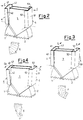
- FIG. 2 to divert the excavation sideways (arrow E) in the plane of the underground wall it is sufficient to extend actuator 10 and withdraw actuator 11 in the same horizontal direction (arrows C).
- FIG. 3 to divert the excavation frontally (arrow F) in a plane perpendicular to that of the underground wall, both actuators 10, 11 are extended parallel in the same direction as indicated by arrow D.
- the actuators 10 and 11 have to be activated in parallel and opposite horizontal directions (arrows D1 and D2).
- the device of this invention provides also for combined corrections of verticality and torsion by suitably controlling rotation of the guides and so attain any possible correction resulting from the combination of two or more of the arrows E, F and G depicted in FIGS. 2 to 4.
- this is accomplished in accordance with the present invention by the provision of only two side guiding means.
- guides 4 and 5 may be mutually connected by horizontal rods 12 and 13 secured so as to allow rotation and torsion shown in FIGS. 2 to 4.
- the guides 4 and 5 may have different shapes from the C one described and illustrated, as far as they have walls adapted to engage the walls of the excavation sideways and/or frontally in order to effect the required deviation.
- the excavating bucket (or drill or other excavating means used) is fitted with sensors (not shown for simplicity) for detecting all data concerning position and inclination of the excavation at the point of the excavating head. These sensors are connected to an on-surface electronic processing unit for controlling correction of inclination and/or torsion in response to errors being possibly detected. The correction may be performed automatically or manually by an operator.
- the sensors can be mounted on the body 3 of the excavating head and/or the movable guides.
- Said sensors comprise: two inclination detectors, one for sensing inclination in the vertical plane of the underground wall and the other for detecting inclination in the vertical plane perpendicular to said plane of the underground wall; a gyroscope for orientation about the excavation axis; and a depth detector for measuring depth.
- a sum of increments calculation method allows to know the position of the excavating tool at any depth during the falling step, and particularly the final position relative to the ideal position.
- the extent of the distance between the excavating bucket and the walls of the excavation may be gauged by an ultrasonic system of known kind (not shown).
- the overall available data (concerning distance from the walls of the excavation, depth, inclination) provide continuous information which enables to know the instantaneous shape of the excavation and modify it if necessary.
- the comparison between the ideal shape of the excavation provides the correction to be made to reduce and nullify any error. Correction can be carried out automatically or by an operator.
Landscapes
- Engineering & Computer Science (AREA)
- Mining & Mineral Resources (AREA)
- Civil Engineering (AREA)
- General Engineering & Computer Science (AREA)
- Structural Engineering (AREA)
- Mechanical Engineering (AREA)
- Life Sciences & Earth Sciences (AREA)
- General Life Sciences & Earth Sciences (AREA)
- Paleontology (AREA)
- Earth Drilling (AREA)
- Bulkheads Adapted To Foundation Construction (AREA)
- Control Of Fluid Pressure (AREA)
- Pit Excavations, Shoring, Fill Or Stabilisation Of Slopes (AREA)
Abstract
Description
- The present invention falls within the field of excavations for constructing concrete underground walls. More particularly, the invention relates to a device for adjusting inclination of an excavating head for said constructions.
- There are known underground walls composed of a series of adjacent panels. Each panel is constructed in an excavation generally of rectangular cross section elongated in the direction of the curtain. The short sides of the rectangular cross section are located adjacent the short sides of the near panels. Excavation is performed by a grab bucket or a drilling bucket with two, four or more toothed rotary boring tools.
- For the stability and efficiency of the work it is important that the wall of the underground wall has no break in continuity, i.e. all adjacent panels must contact throughout the whole depth. Therefore, the long sides and short sides of each panel must be vertical. Moreover, helical torsion of a single panel has to be avoided. It is actually possible that some panels, although being contiguous at the top and having vertical axes, form gaps therebetween under a certain depth due to torsion about the vertical axis. Verticality of the panel sides during excavation is so of primary importance.
- Verticality errors are caused by irregularities in the soil and rocks lying on the vertical excavation axis, whilst torsion errors are due to the twisting of the rope during rising and falling of the excavating head.
- At present, most buckets or other devices for excavating continuous underground walls are provided with guide elements for limiting deviation from the vertical line. Recent kinds of such elements are capable of accomplishing adjusting movements for correcting the inclination of the excavation and are fitted with sensors for detecting the direction and the extent of a verticality error.
- WO 94/21864 discloses a device for maintaining the vertical excavation direction of a subterranean curtain. The device comprises an outer guiding body suspended to an excavator by a rope. A hydraulic clamshell is mounted to an orientable body linked within the outer guiding body so as to correct the excavation inclination relative to the plane of the curtain. Inclination detectors are mounted to the outer and/or inner orientable body. The signals from the detectors are transmitted to a control device which, in the event of the deviation of the clamshell body from the predetermined vertical direction, compensates therefor by pivoting the inner body in relation to the guide in the opposite direction to that of the deviation.
- JP-A-3-241 118 discloses an excavator of underground continuous walls making use of an automatic system for correction inclination of the excavation. Twelve movable surfaces are mounted to the excavating head, six at a higher level and six at a lower level. Said surfaces can be singularly urged towards or retracted from the excavation walls perpendicularly thereto for engaging said walls in sliding contact so as to correct the position of the excavating head and eliminate play relative to the excavation walls.
- It is an object of the present invention to provide a device for correcting the excavation inclination whereby inclination can be adjusted in the plane of the wall as well as in a vertical plane perpendicular to the plane of the wall and also torsion about the vertical line can be corrected.
- It is another object of the present invention to provide a device of simple construction capable of performing all the adjustments required through a reduced number of controls, thereby being easier to direct.
- In accordance with one aspect of the invention as claimed, these objects are accomplished by the provision of a device for adjusting inclination of an excavating head for constructing concrete underground walls, of the type comprising a plurality of movable surfaces mounted to the excavating head and capable of being selectively urged against the walls of the excavation. The device is characterised in that said surfaces are comprised of a pair of rigid, substantially vertical guide means mounted on two opposite vertical sides of the excavating head. The guide means have bottom portions linked so as to accomplish rotation in a respective vertical plane by means of upper actuator means.
- In order that the present invention may be well understood there will now be described a preferred embodiment thereof, given by way of example, reference being made to the accompanying drawings, in which:
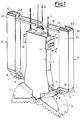
- FIG. 1
- is an exploded perspective view schematically showing an embodiment of the device of this invention applied to a an excavating bucket; and
- FIGS. 2, 3 and 4
- schematically depict a number of operations which the device of FIG. 1 is capable of carrying out.
- With reference initially to FIG. 1,
numeral 3 designates the body of a conventional excavating bucket suspended to a rope 6. The excavatingbucket 3 is fitted withlower clamshells - Although the present example refers to a bucket excavating means, it is understood that the device of this invention is equally applicable to excavating apparatuses of different kind, for example those exploiting drilling means.
- In accordance with the present invention, coupled to the excavating bucket is a pair of
movable guides bucket body 3.Guides - In the preferred embodiment shown in the drawings, the
guides bucket body 3. Each guide has three outer walls: a side wall (41 and 51), and two front opposite walls (42, 43 and 52, 53). Preferably, the guides have a C-shaped cross section wide enough not to interfere with thebody 3 of the excavating head as they move relative thereto. As an alternative, the guides may be mounted spaced apart from thebody 3 in such manner to avoid any contact with it. The example illustrated in the drawings shows that the distance between the opposite front walls of each guide is greater than the thickness ofbody 3. - The
guides pivotal connections pivotal connection pivotal connections - The top portion of each guide is secured to
actuators actuators Actuators - Owing to the lower linkage which allows the lateral guides to accomplish single (arrows A and B) or combined rotation in vertical planes under the action of respective actuators, the device according to the present invention allows to carry out all the possible corrections of the inclination. As shown in FIG. 2, to divert the excavation sideways (arrow E) in the plane of the underground wall it is sufficient to extend
actuator 10 and withdrawactuator 11 in the same horizontal direction (arrows C). Similarly, as shown in FIG. 3, to divert the excavation frontally (arrow F) in a plane perpendicular to that of the underground wall, bothactuators actuators - Obviously, the device of this invention provides also for combined corrections of verticality and torsion by suitably controlling rotation of the guides and so attain any possible correction resulting from the combination of two or more of the arrows E, F and G depicted in FIGS. 2 to 4. Advantageously, this is accomplished in accordance with the present invention by the provision of only two side guiding means.
- Still referring to FIG. 1, the upper end portions of
guides horizontal rods - Alternatively, the
guides - The excavating bucket (or drill or other excavating means used) is fitted with sensors (not shown for simplicity) for detecting all data concerning position and inclination of the excavation at the point of the excavating head. These sensors are connected to an on-surface electronic processing unit for controlling correction of inclination and/or torsion in response to errors being possibly detected. The correction may be performed automatically or manually by an operator.
- The sensors can be mounted on the
body 3 of the excavating head and/or the movable guides. Said sensors comprise: two inclination detectors, one for sensing inclination in the vertical plane of the underground wall and the other for detecting inclination in the vertical plane perpendicular to said plane of the underground wall; a gyroscope for orientation about the excavation axis; and a depth detector for measuring depth. A sum of increments calculation method allows to know the position of the excavating tool at any depth during the falling step, and particularly the final position relative to the ideal position. - The extent of the distance between the excavating bucket and the walls of the excavation may be gauged by an ultrasonic system of known kind (not shown). The overall available data (concerning distance from the walls of the excavation, depth, inclination) provide continuous information which enables to know the instantaneous shape of the excavation and modify it if necessary.
- The comparison between the ideal shape of the excavation provides the correction to be made to reduce and nullify any error. Correction can be carried out automatically or by an operator.
- The disclosures in Italian patent application No. TO96A000125 from which this application claims priority, and in the abstract accompanying this application are incorporated herein by reference.
Claims (8)
- A device for adjusting inclination of an excavating head for constructing concrete underground walls, of the type comprising a plurality of movable surfaces mounted to the excavating head (3) and capable of being selectively urged against the walls of the excavation, characterised in that said surfaces are comprised of a pair of rigid, substantially vertical guide means (4, 5) mounted on two opposite vertical sides of the excavating head, said guide means (4, 5) having bottom portions linked (8, 9, 15, 16) so as to accomplish rotation in a respective vertical plane by means of upper actuator means (10, 11).
- A device as claimed in claim 1, characterised in that each of said actuator means (10, 11) is capable of acting along perpendicular directions (C, D) in a substantially horizontal plane.
- A device as claimed in claim 1, characterised in that said actuator means (10, 11) are independent.
- A device as claimed in claim 1, characterised in that each guide means (4, 5) is linked by two lower pivotal connections (8, 15; 9, 16) about horizontal axes perpendicular therebetween.
- A device as claimed in claim 1, characterised in that said guide means (4, 5) have a C-shaped cross section with the open portions of the section facing the body (3) of the excavating head.
- A device as claimed in claim 5, characterised in that the C-shaped cross section of said guide means (4, 5) is wide enough not to interfere with said body (3) of the excavating head while moving with respect thereto.
- A device as claimed in any of the preceding claims, characterised by being provided with inclination sensor means, depth sensor means, and means for sensing the orientation of the excavating head.
- A device as claimed in any of the preceding claims, characterised by comprising means for detecting the distance between the excavating head and the walls of the excavation.
Applications Claiming Priority (2)
| Application Number | Priority Date | Filing Date | Title |
|---|---|---|---|
| ITTO960125 | 1996-02-26 | ||
| IT96TO000125A IT1285259B1 (en) | 1996-02-26 | 1996-02-26 | DEVICE FOR ADJUSTING THE INCLINATION OF AN EXCAVATION HEAD FOR THE CONSTRUCTION OF CONCRETE DIAPHRAGMs. |
Publications (3)
| Publication Number | Publication Date |
|---|---|
| EP0791690A1 true EP0791690A1 (en) | 1997-08-27 |
| EP0791690B1 EP0791690B1 (en) | 2002-04-17 |
| EP0791690B2 EP0791690B2 (en) | 2004-11-24 |
Family
ID=11414296
Family Applications (1)
| Application Number | Title | Priority Date | Filing Date |
|---|---|---|---|
| EP97102378A Expired - Lifetime EP0791690B2 (en) | 1996-02-26 | 1997-02-14 | A device for adjusting inclination of an excavating head for constructing concrete underground walls |
Country Status (5)
| Country | Link |
|---|---|
| EP (1) | EP0791690B2 (en) |
| CN (1) | CN1119467C (en) |
| DE (1) | DE69711969T3 (en) |
| ES (1) | ES2176537T5 (en) |
| IT (1) | IT1285259B1 (en) |
Cited By (10)
| Publication number | Priority date | Publication date | Assignee | Title |
|---|---|---|---|---|
| FR2785946A1 (en) | 1998-11-18 | 2000-05-19 | Spie Fondations | Method of drilling for building foundations uses radio link between tool head position sensor and operator display |
| EP1162317A3 (en) * | 2000-06-09 | 2002-05-15 | Kobelco Construction Machinery Co., Ltd. | Excavator for a ditch and excavating method therefor |
| FR2825393A1 (en) * | 2001-06-01 | 2002-12-06 | Cie Du Sol | Bucket hoist crane has positional correction via bucket runners controlled by angle sensors |
| EP0919669B1 (en) * | 1997-11-25 | 2004-02-18 | Compagnie Du Sol | Grab bucket with verticality correction |
| EP1630297A1 (en) * | 2004-08-20 | 2006-03-01 | BAUER Maschinen GmbH | Method of making concrete underground walls and device therefor |
| GB2417942A (en) * | 2004-09-09 | 2006-03-15 | Cementation Found Skanska Ltd | Method and apparatus for excavation of a trench |
| EP1748110A2 (en) | 2005-07-22 | 2007-01-31 | SOILMEC S.p.A. | Method and device for mixing earth in situ for the formation of underground walls or diaphragms |
| EP1964980A1 (en) * | 2007-02-28 | 2008-09-03 | Etienne Heirwegh | Excavating means and method to cast in-situ cast walls |
| EP3725955A1 (en) * | 2019-04-18 | 2020-10-21 | BAUER Maschinen GmbH | Slotted wall gripper and method for creating a slot in the ground |
| KR102192275B1 (en) * | 2019-07-09 | 2020-12-17 | 손재방 | Adjustable wall grab for excavation |
Families Citing this family (7)
| Publication number | Priority date | Publication date | Assignee | Title |
|---|---|---|---|---|
| DE102007035591B3 (en) | 2007-07-30 | 2008-10-23 | Bauer Maschinen Gmbh | Civil engineering device for creating slots in the ground |
| CN101440624B (en) * | 2007-11-22 | 2011-01-19 | 北京市三一重机有限公司 | Self-adjusting guide means |
| CN101440626B (en) * | 2007-11-22 | 2010-12-22 | 北京市三一重机有限公司 | Swing type deviation rectifying apparatus |
| CN103306603B (en) * | 2013-06-28 | 2015-10-07 | 葛洲坝集团基础工程有限公司 | Method for correcting error in a kind of diaphragm wall unit groove sector hole |
| CN108064535A (en) * | 2018-01-18 | 2018-05-25 | 广西田阳煦日农业科技发展有限公司 | It is a kind of to dig non-irrigated lotus root structure |
| CN113323046B (en) * | 2021-05-25 | 2021-11-26 | 徐州徐工基础工程机械有限公司 | Righting device of double-wheel slot milling machine |
| CN115045355B (en) * | 2022-05-30 | 2023-06-06 | 中交二公局铁路建设有限公司 | Grab bucket assembly device of grooving machine for grabbing and breaking anchor cable and application method of grab bucket assembly device |
Citations (5)
| Publication number | Priority date | Publication date | Assignee | Title |
|---|---|---|---|---|
| US4718504A (en) * | 1985-03-15 | 1988-01-12 | Tone Boring Co., Ltd. | Trench excavator |
| DE3805868A1 (en) * | 1988-02-25 | 1989-09-07 | Hochtief Ag Hoch Tiefbauten | Rope-guided trench-wall grab |
| JPH03241118A (en) | 1990-02-19 | 1991-10-28 | Fujita Corp | Automatic excavator of underground continuous wall |
| EP0518298A1 (en) * | 1991-06-11 | 1992-12-16 | Bauer Spezialtiefbau GmbH | Milling device for slits and milling method |
| WO1994021864A1 (en) | 1993-03-23 | 1994-09-29 | Stahl- Und Apparatebau Hans Leffer Gmbh | Process and device for precisely maintaining the vertical excavation direction of a subterranean curtain |
Family Cites Families (3)
| Publication number | Priority date | Publication date | Assignee | Title |
|---|---|---|---|---|
| US2781140A (en) * | 1955-10-20 | 1957-02-12 | Shaft Machines Ltd | Mucking machine |
| DE3602387C1 (en) * | 1986-01-28 | 1987-06-04 | Hochtief Ag Hoch Tiefbauten | Device for introducing a substantially vertical bottom slot |
| DE3615068C1 (en) * | 1986-05-03 | 1987-10-08 | Dyckerhoff & Widmann Ag | Rope-guided trench-wall grab |
-
1996
- 1996-02-26 IT IT96TO000125A patent/IT1285259B1/en active IP Right Grant
-
1997
- 1997-02-14 DE DE69711969T patent/DE69711969T3/en not_active Expired - Lifetime
- 1997-02-14 EP EP97102378A patent/EP0791690B2/en not_active Expired - Lifetime
- 1997-02-14 ES ES97102378T patent/ES2176537T5/en not_active Expired - Lifetime
- 1997-02-25 CN CN97102555.XA patent/CN1119467C/en not_active Expired - Lifetime
Patent Citations (5)
| Publication number | Priority date | Publication date | Assignee | Title |
|---|---|---|---|---|
| US4718504A (en) * | 1985-03-15 | 1988-01-12 | Tone Boring Co., Ltd. | Trench excavator |
| DE3805868A1 (en) * | 1988-02-25 | 1989-09-07 | Hochtief Ag Hoch Tiefbauten | Rope-guided trench-wall grab |
| JPH03241118A (en) | 1990-02-19 | 1991-10-28 | Fujita Corp | Automatic excavator of underground continuous wall |
| EP0518298A1 (en) * | 1991-06-11 | 1992-12-16 | Bauer Spezialtiefbau GmbH | Milling device for slits and milling method |
| WO1994021864A1 (en) | 1993-03-23 | 1994-09-29 | Stahl- Und Apparatebau Hans Leffer Gmbh | Process and device for precisely maintaining the vertical excavation direction of a subterranean curtain |
Non-Patent Citations (1)
| Title |
|---|
| PATENT ABSTRACTS OF JAPAN vol. 016, no. 030 (M - 1203) 24 January 1992 (1992-01-24) * |
Cited By (15)
| Publication number | Priority date | Publication date | Assignee | Title |
|---|---|---|---|---|
| EP0919669B1 (en) * | 1997-11-25 | 2004-02-18 | Compagnie Du Sol | Grab bucket with verticality correction |
| FR2785946A1 (en) | 1998-11-18 | 2000-05-19 | Spie Fondations | Method of drilling for building foundations uses radio link between tool head position sensor and operator display |
| EP1162317A3 (en) * | 2000-06-09 | 2002-05-15 | Kobelco Construction Machinery Co., Ltd. | Excavator for a ditch and excavating method therefor |
| US6536142B2 (en) | 2000-06-09 | 2003-03-25 | Kobelco Construction Machinery Co., Ltd. | Excavator for a ditch and excavating method therefor |
| FR2825393A1 (en) * | 2001-06-01 | 2002-12-06 | Cie Du Sol | Bucket hoist crane has positional correction via bucket runners controlled by angle sensors |
| EP1264937A3 (en) * | 2001-06-01 | 2003-01-29 | Compagnie Du Sol | Grab bucket for trench walls with improved control system for the verticality of the excavation |
| EP1630297A1 (en) * | 2004-08-20 | 2006-03-01 | BAUER Maschinen GmbH | Method of making concrete underground walls and device therefor |
| DE102005017092B4 (en) * | 2004-08-20 | 2009-04-16 | Bauer Maschinen Gmbh | Method of making a trench wall in the ground, trench wall cutter and trench wall underpinning |
| GB2417942A (en) * | 2004-09-09 | 2006-03-15 | Cementation Found Skanska Ltd | Method and apparatus for excavation of a trench |
| GB2417942B (en) * | 2004-09-09 | 2008-04-09 | Cementation Found Skanska Ltd | Method and apparatus for excavation of a trench |
| EP1748110A2 (en) | 2005-07-22 | 2007-01-31 | SOILMEC S.p.A. | Method and device for mixing earth in situ for the formation of underground walls or diaphragms |
| EP1748110A3 (en) * | 2005-07-22 | 2008-09-10 | SOILMEC S.p.A. | Method and device for mixing earth in situ for the formation of underground walls or diaphragms |
| EP1964980A1 (en) * | 2007-02-28 | 2008-09-03 | Etienne Heirwegh | Excavating means and method to cast in-situ cast walls |
| EP3725955A1 (en) * | 2019-04-18 | 2020-10-21 | BAUER Maschinen GmbH | Slotted wall gripper and method for creating a slot in the ground |
| KR102192275B1 (en) * | 2019-07-09 | 2020-12-17 | 손재방 | Adjustable wall grab for excavation |
Also Published As
| Publication number | Publication date |
|---|---|
| ITTO960125A1 (en) | 1997-08-26 |
| CN1162673A (en) | 1997-10-22 |
| CN1119467C (en) | 2003-08-27 |
| ES2176537T3 (en) | 2002-12-01 |
| EP0791690B1 (en) | 2002-04-17 |
| IT1285259B1 (en) | 1998-06-03 |
| DE69711969T3 (en) | 2005-06-09 |
| DE69711969D1 (en) | 2002-05-23 |
| EP0791690B2 (en) | 2004-11-24 |
| ITTO960125A0 (en) | 1996-02-26 |
| ES2176537T5 (en) | 2005-06-16 |
| DE69711969T2 (en) | 2002-08-14 |
Similar Documents
| Publication | Publication Date | Title |
|---|---|---|
| EP0791690B1 (en) | A device for adjusting inclination of an excavating head for constructing concrete underground walls | |
| CN1085759C (en) | Process and device for precisely maintaining the vertical excavation direction of a subterranean curtain | |
| US5933346A (en) | Bucket depth and angle controller for excavator | |
| JP2598205B2 (en) | Groove excavator and method of operation | |
| JPH0953253A (en) | Excavation area setting device for area limitation excavation control of construction machinery | |
| JP4048743B2 (en) | Bucket excavator | |
| JPH0224423A (en) | Excavator | |
| JPS5965130A (en) | Apparatus for revolving attaching holder of attachment of hydraulic drill machine | |
| JP2007327334A (en) | Bucket type excavator | |
| JPH11117656A (en) | Drilling equipment mounted on excavator | |
| JPS6337210B2 (en) | ||
| JP2676696B2 (en) | Ground drilling rig | |
| JP3538685B2 (en) | Excavator displacement measurement device | |
| JP2597919B2 (en) | Excavator position detector | |
| JPH01111985A (en) | Vertical plumbing precision controller of excavator for method of reverse circulation construction | |
| HK40057919A (en) | Digging machine with a frame equipped with guiding wings | |
| US20080066350A1 (en) | Method and Apparatus for Excavation of a Trench | |
| SU1158697A1 (en) | Guiding device for working trenches | |
| JPH0240095Y2 (en) | ||
| EP2226427A2 (en) | Excavation apparatus | |
| JP3005872B2 (en) | Excavation direction correction device for excavation casing | |
| KR101549036B1 (en) | Diaphragm wall excavator | |
| JPH01203585A (en) | Excavator horizontal displacement detection method and device | |
| HK40057919B (en) | Digging machine with a frame equipped with guiding wings | |
| JPH0634425Y2 (en) | Posture correction device |
Legal Events
| Date | Code | Title | Description |
|---|---|---|---|
| PUAI | Public reference made under article 153(3) epc to a published international application that has entered the european phase |
Free format text: ORIGINAL CODE: 0009012 |
|
| AK | Designated contracting states |
Kind code of ref document: A1 Designated state(s): DE ES FR GB IT |
|
| 17P | Request for examination filed |
Effective date: 19971002 |
|
| 17Q | First examination report despatched |
Effective date: 19991111 |
|
| GRAG | Despatch of communication of intention to grant |
Free format text: ORIGINAL CODE: EPIDOS AGRA |
|
| GRAG | Despatch of communication of intention to grant |
Free format text: ORIGINAL CODE: EPIDOS AGRA |
|
| GRAH | Despatch of communication of intention to grant a patent |
Free format text: ORIGINAL CODE: EPIDOS IGRA |
|
| GRAH | Despatch of communication of intention to grant a patent |
Free format text: ORIGINAL CODE: EPIDOS IGRA |
|
| REG | Reference to a national code |
Ref country code: GB Ref legal event code: IF02 |
|
| GRAA | (expected) grant |
Free format text: ORIGINAL CODE: 0009210 |
|
| AK | Designated contracting states |
Kind code of ref document: B1 Designated state(s): DE ES FR GB IT |
|
| REF | Corresponds to: |
Ref document number: 69711969 Country of ref document: DE Date of ref document: 20020523 |
|
| ET | Fr: translation filed | ||
| REG | Reference to a national code |
Ref country code: ES Ref legal event code: FG2A Ref document number: 2176537 Country of ref document: ES Kind code of ref document: T3 |
|
| PLBI | Opposition filed |
Free format text: ORIGINAL CODE: 0009260 |
|
| PLBQ | Unpublished change to opponent data |
Free format text: ORIGINAL CODE: EPIDOS OPPO |
|
| PLBF | Reply of patent proprietor to notice(s) of opposition |
Free format text: ORIGINAL CODE: EPIDOS OBSO |
|
| 26 | Opposition filed |
Opponent name: BAUER MASCHINEN GMBH Effective date: 20030117 |
|
| PLBF | Reply of patent proprietor to notice(s) of opposition |
Free format text: ORIGINAL CODE: EPIDOS OBSO |
|
| PLBB | Reply of patent proprietor to notice(s) of opposition received |
Free format text: ORIGINAL CODE: EPIDOSNOBS3 |
|
| PUAH | Patent maintained in amended form |
Free format text: ORIGINAL CODE: 0009272 |
|
| STAA | Information on the status of an ep patent application or granted ep patent |
Free format text: STATUS: PATENT MAINTAINED AS AMENDED |
|
| 27A | Patent maintained in amended form |
Effective date: 20041124 |
|
| AK | Designated contracting states |
Kind code of ref document: B2 Designated state(s): DE ES FR GB IT |
|
| REG | Reference to a national code |
Ref country code: ES Ref legal event code: DC2A Date of ref document: 20050223 Kind code of ref document: T5 |
|
| ET3 | Fr: translation filed ** decision concerning opposition | ||
| PG25 | Lapsed in a contracting state [announced via postgrant information from national office to epo] |
Ref country code: IT Free format text: LAPSE BECAUSE OF NON-PAYMENT OF DUE FEES Effective date: 20090214 |
|
| PGRI | Patent reinstated in contracting state [announced from national office to epo] |
Ref country code: IT Effective date: 20110616 |
|
| PGFP | Annual fee paid to national office [announced via postgrant information from national office to epo] |
Ref country code: GB Payment date: 20120208 Year of fee payment: 16 |
|
| PGFP | Annual fee paid to national office [announced via postgrant information from national office to epo] |
Ref country code: ES Payment date: 20120307 Year of fee payment: 16 |
|
| GBPC | Gb: european patent ceased through non-payment of renewal fee |
Effective date: 20130214 |
|
| PG25 | Lapsed in a contracting state [announced via postgrant information from national office to epo] |
Ref country code: GB Free format text: LAPSE BECAUSE OF NON-PAYMENT OF DUE FEES Effective date: 20130214 |
|
| REG | Reference to a national code |
Ref country code: ES Ref legal event code: FD2A Effective date: 20140409 |
|
| PG25 | Lapsed in a contracting state [announced via postgrant information from national office to epo] |
Ref country code: ES Free format text: LAPSE BECAUSE OF NON-PAYMENT OF DUE FEES Effective date: 20130215 |
|
| REG | Reference to a national code |
Ref country code: FR Ref legal event code: PLFP Year of fee payment: 20 |
|
| PGFP | Annual fee paid to national office [announced via postgrant information from national office to epo] |
Ref country code: IT Payment date: 20160216 Year of fee payment: 20 Ref country code: DE Payment date: 20160209 Year of fee payment: 20 |
|
| PGFP | Annual fee paid to national office [announced via postgrant information from national office to epo] |
Ref country code: FR Payment date: 20160108 Year of fee payment: 20 |
|
| REG | Reference to a national code |
Ref country code: DE Ref legal event code: R071 Ref document number: 69711969 Country of ref document: DE |