EP0790875B1 - Procede et dispositif de production de pieces metalliques - Google Patents
Procede et dispositif de production de pieces metalliques Download PDFInfo
- Publication number
- EP0790875B1 EP0790875B1 EP96927576A EP96927576A EP0790875B1 EP 0790875 B1 EP0790875 B1 EP 0790875B1 EP 96927576 A EP96927576 A EP 96927576A EP 96927576 A EP96927576 A EP 96927576A EP 0790875 B1 EP0790875 B1 EP 0790875B1
- Authority
- EP
- European Patent Office
- Prior art keywords
- powder
- laser beam
- head
- layer
- layers
- Prior art date
- Legal status (The legal status is an assumption and is not a legal conclusion. Google has not performed a legal analysis and makes no representation as to the accuracy of the status listed.)
- Expired - Lifetime
Links
Images


Classifications
-
- B—PERFORMING OPERATIONS; TRANSPORTING
- B23—MACHINE TOOLS; METAL-WORKING NOT OTHERWISE PROVIDED FOR
- B23K—SOLDERING OR UNSOLDERING; WELDING; CLADDING OR PLATING BY SOLDERING OR WELDING; CUTTING BY APPLYING HEAT LOCALLY, e.g. FLAME CUTTING; WORKING BY LASER BEAM
- B23K26/00—Working by laser beam, e.g. welding, cutting or boring
- B23K26/34—Laser welding for purposes other than joining
-
- B—PERFORMING OPERATIONS; TRANSPORTING
- B23—MACHINE TOOLS; METAL-WORKING NOT OTHERWISE PROVIDED FOR
- B23K—SOLDERING OR UNSOLDERING; WELDING; CLADDING OR PLATING BY SOLDERING OR WELDING; CUTTING BY APPLYING HEAT LOCALLY, e.g. FLAME CUTTING; WORKING BY LASER BEAM
- B23K26/00—Working by laser beam, e.g. welding, cutting or boring
- B23K26/14—Working by laser beam, e.g. welding, cutting or boring using a fluid stream, e.g. a jet of gas, in conjunction with the laser beam; Nozzles therefor
- B23K26/142—Working by laser beam, e.g. welding, cutting or boring using a fluid stream, e.g. a jet of gas, in conjunction with the laser beam; Nozzles therefor for the removal of by-products
-
- B—PERFORMING OPERATIONS; TRANSPORTING
- B23—MACHINE TOOLS; METAL-WORKING NOT OTHERWISE PROVIDED FOR
- B23K—SOLDERING OR UNSOLDERING; WELDING; CLADDING OR PLATING BY SOLDERING OR WELDING; CUTTING BY APPLYING HEAT LOCALLY, e.g. FLAME CUTTING; WORKING BY LASER BEAM
- B23K26/00—Working by laser beam, e.g. welding, cutting or boring
- B23K26/14—Working by laser beam, e.g. welding, cutting or boring using a fluid stream, e.g. a jet of gas, in conjunction with the laser beam; Nozzles therefor
- B23K26/144—Working by laser beam, e.g. welding, cutting or boring using a fluid stream, e.g. a jet of gas, in conjunction with the laser beam; Nozzles therefor the fluid stream containing particles, e.g. powder
-
- B—PERFORMING OPERATIONS; TRANSPORTING
- B23—MACHINE TOOLS; METAL-WORKING NOT OTHERWISE PROVIDED FOR
- B23K—SOLDERING OR UNSOLDERING; WELDING; CLADDING OR PLATING BY SOLDERING OR WELDING; CUTTING BY APPLYING HEAT LOCALLY, e.g. FLAME CUTTING; WORKING BY LASER BEAM
- B23K26/00—Working by laser beam, e.g. welding, cutting or boring
- B23K26/20—Bonding
- B23K26/32—Bonding taking account of the properties of the material involved
-
- B—PERFORMING OPERATIONS; TRANSPORTING
- B23—MACHINE TOOLS; METAL-WORKING NOT OTHERWISE PROVIDED FOR
- B23P—METAL-WORKING NOT OTHERWISE PROVIDED FOR; COMBINED OPERATIONS; UNIVERSAL MACHINE TOOLS
- B23P23/00—Machines or arrangements of machines for performing specified combinations of different metal-working operations not covered by a single other subclass
- B23P23/04—Machines or arrangements of machines for performing specified combinations of different metal-working operations not covered by a single other subclass for both machining and other metal-working operations
-
- B—PERFORMING OPERATIONS; TRANSPORTING
- B29—WORKING OF PLASTICS; WORKING OF SUBSTANCES IN A PLASTIC STATE IN GENERAL
- B29C—SHAPING OR JOINING OF PLASTICS; SHAPING OF MATERIAL IN A PLASTIC STATE, NOT OTHERWISE PROVIDED FOR; AFTER-TREATMENT OF THE SHAPED PRODUCTS, e.g. REPAIRING
- B29C64/00—Additive manufacturing, i.e. manufacturing of three-dimensional [3D] objects by additive deposition, additive agglomeration or additive layering, e.g. by 3D printing, stereolithography or selective laser sintering
- B29C64/10—Processes of additive manufacturing
- B29C64/141—Processes of additive manufacturing using only solid materials
- B29C64/153—Processes of additive manufacturing using only solid materials using layers of powder being selectively joined, e.g. by selective laser sintering or melting
-
- B—PERFORMING OPERATIONS; TRANSPORTING
- B29—WORKING OF PLASTICS; WORKING OF SUBSTANCES IN A PLASTIC STATE IN GENERAL
- B29C—SHAPING OR JOINING OF PLASTICS; SHAPING OF MATERIAL IN A PLASTIC STATE, NOT OTHERWISE PROVIDED FOR; AFTER-TREATMENT OF THE SHAPED PRODUCTS, e.g. REPAIRING
- B29C64/00—Additive manufacturing, i.e. manufacturing of three-dimensional [3D] objects by additive deposition, additive agglomeration or additive layering, e.g. by 3D printing, stereolithography or selective laser sintering
- B29C64/10—Processes of additive manufacturing
- B29C64/188—Processes of additive manufacturing involving additional operations performed on the added layers, e.g. smoothing, grinding or thickness control
-
- B—PERFORMING OPERATIONS; TRANSPORTING
- B22—CASTING; POWDER METALLURGY
- B22F—WORKING METALLIC POWDER; MANUFACTURE OF ARTICLES FROM METALLIC POWDER; MAKING METALLIC POWDER; APPARATUS OR DEVICES SPECIALLY ADAPTED FOR METALLIC POWDER
- B22F10/00—Additive manufacturing of workpieces or articles from metallic powder
- B22F10/20—Direct sintering or melting
- B22F10/25—Direct deposition of metal particles, e.g. direct metal deposition [DMD] or laser engineered net shaping [LENS]
-
- B—PERFORMING OPERATIONS; TRANSPORTING
- B22—CASTING; POWDER METALLURGY
- B22F—WORKING METALLIC POWDER; MANUFACTURE OF ARTICLES FROM METALLIC POWDER; MAKING METALLIC POWDER; APPARATUS OR DEVICES SPECIALLY ADAPTED FOR METALLIC POWDER
- B22F12/00—Apparatus or devices specially adapted for additive manufacturing; Auxiliary means for additive manufacturing; Combinations of additive manufacturing apparatus or devices with other processing apparatus or devices
- B22F12/40—Radiation means
- B22F12/41—Radiation means characterised by the type, e.g. laser or electron beam
-
- B—PERFORMING OPERATIONS; TRANSPORTING
- B22—CASTING; POWDER METALLURGY
- B22F—WORKING METALLIC POWDER; MANUFACTURE OF ARTICLES FROM METALLIC POWDER; MAKING METALLIC POWDER; APPARATUS OR DEVICES SPECIALLY ADAPTED FOR METALLIC POWDER
- B22F3/00—Manufacture of workpieces or articles from metallic powder characterised by the manner of compacting or sintering; Apparatus specially adapted therefor ; Presses and furnaces
- B22F3/24—After-treatment of workpieces or articles
- B22F2003/247—Removing material: carving, cleaning, grinding, hobbing, honing, lapping, polishing, milling, shaving, skiving, turning the surface
-
- B—PERFORMING OPERATIONS; TRANSPORTING
- B23—MACHINE TOOLS; METAL-WORKING NOT OTHERWISE PROVIDED FOR
- B23K—SOLDERING OR UNSOLDERING; WELDING; CLADDING OR PLATING BY SOLDERING OR WELDING; CUTTING BY APPLYING HEAT LOCALLY, e.g. FLAME CUTTING; WORKING BY LASER BEAM
- B23K2103/00—Materials to be soldered, welded or cut
- B23K2103/50—Inorganic material, e.g. metals, not provided for in B23K2103/02 – B23K2103/26
-
- B—PERFORMING OPERATIONS; TRANSPORTING
- B29—WORKING OF PLASTICS; WORKING OF SUBSTANCES IN A PLASTIC STATE IN GENERAL
- B29K—INDEXING SCHEME ASSOCIATED WITH SUBCLASSES B29B, B29C OR B29D, RELATING TO MOULDING MATERIALS OR TO MATERIALS FOR MOULDS, REINFORCEMENTS, FILLERS OR PREFORMED PARTS, e.g. INSERTS
- B29K2995/00—Properties of moulding materials, reinforcements, fillers, preformed parts or moulds
- B29K2995/0037—Other properties
- B29K2995/0072—Roughness, e.g. anti-slip
- B29K2995/0073—Roughness, e.g. anti-slip smooth
-
- Y—GENERAL TAGGING OF NEW TECHNOLOGICAL DEVELOPMENTS; GENERAL TAGGING OF CROSS-SECTIONAL TECHNOLOGIES SPANNING OVER SEVERAL SECTIONS OF THE IPC; TECHNICAL SUBJECTS COVERED BY FORMER USPC CROSS-REFERENCE ART COLLECTIONS [XRACs] AND DIGESTS
- Y02—TECHNOLOGIES OR APPLICATIONS FOR MITIGATION OR ADAPTATION AGAINST CLIMATE CHANGE
- Y02P—CLIMATE CHANGE MITIGATION TECHNOLOGIES IN THE PRODUCTION OR PROCESSING OF GOODS
- Y02P10/00—Technologies related to metal processing
- Y02P10/25—Process efficiency
Definitions
- the present invention relates to a method for manufacturing of metallic workpieces, especially of molds, where with a laser beam metal-containing powder a melting area of the laser beam is melted in layers is then machined and applied layers become.
- the invention relates to a Device for the production of metallic workpieces, especially for carrying out the method, with a coating device, which is a laser unit with a laser beam focusing head and a powder feeder for feeding metal-containing powder into a melting area of the laser beam, and a cutting device.
- EP-A-0 558 870 shows Method for free-form welding of metal structures, using a laser Metal powder or metal wire is melted onto a substrate by repeated application is, the part of the metal structure already manufactured itself as Serves substrate.
- a method according to the preamble of claim 1 and a device according to the preamble of claim 20 for the production of metallic workpieces have been proposed, which combine the layer-by-layer melting of metal-containing powder by means of a laser beam and machining by means of a cutting device (ML Murphy et al., The Rapid Manufacture of Metallic Components by Laser Surface Cladding, in: Laser Assisted Net-shape Engineering, Proceedings of the LANE '94, Vol. II, pages 803-814).
- a coating device which has a CO 2 laser and a powder feed device, is mounted on a milling machine.
- a focusing head which focuses the laser beam, can be clamped in the tool clamping device of the milling machine and is arranged coaxially with the spindle of the milling machine.
- the powder feed device has a tube arranged laterally for this purpose, through which metal-containing powder is fed obliquely into a melting region of the laser beam. With a laser beam focusing point diameter of several millimeters (1 mm - 5 mm), tracks with a thickness in the range greater than 1 mm are applied).
- the present invention is therefore based on the object an improved method and device of the type mentioned at the outset, which are the manufacture of metallic workpieces even in the fine area with increased accuracy allow.
- this task becomes one method of the type mentioned at the outset in accordance with the invention, that the powder coaxial to the laser beam in the Melting range is supplied and the individual layers in Tracks with a width in the range of 0.1 mm - 1 mm and one Thickness in the range of 0.05 mm - 0.5 mm can be applied.
- the coaxial feed of the powder ensures one compared to that arranged laterally Powder nozzle uniform, direction-independent material application especially when applying very thin traces are.
- the application of the individual layers in traces of the above size ranges further reduces the Effort in the post-processing since the layers very precise and close already during the coating process the desired final shape of the workpiece.
- An advantageous embodiment of the invention consists in that the tracks with a width in the range of 0.2 mm - 0.5 mm and a thickness in the range of 0.05 mm - 0.2 mm applied become.
- a preferred embodiment of the invention becomes a single layer in traces of different geometry upset.
- Preferred are in edge zones of a layer Traces of relatively small width and thickness applied, while in a core zone of the layer with relative traces larger width and greater thickness can be applied.
- a layer with very high performance manufactured with high accuracy is generated with high build-up capacity, i.e. with larger beam diameter, higher beam power and more powder.
- the decisive factors for accuracy Edge zones of a layer can be distinguished by the fine Shape tracks with high accuracy.
- a preferred embodiment of the invention also consists in that traces in core zones of different layers in be applied in different directions.
- the change the orientation of the filling traces in the core zones of the layer to layer increases the flatness of the surface to be created.
- the powder is melted at a laser power of preferably less than 1 kW.
- Laser sources the beams of which can be transmitted with optical fibers, in particular an Nd-YAG laser, are preferably used.
- a CO 2 laser is used.
- a preferred embodiment of the method according to the invention is that the layers applied each can be reworked individually.
- the last applied layer before applying one another layer on top, on which the further Layer is applied machined while a contour side the last layer applied before applying the another layer remains unprocessed.
- a contour side the last layer applied before applying the another layer remains unprocessed.
- the last top layer applied is on hers Contour sides hereby beyond a target contour, so that another layer melted beyond the target contour can be and especially the peripheral areas can be filled in at the target contour.
- the separate post-processing of one or more applied layers reduce post-processing to a two-dimensional processing of the last generated Layers with constant cutting conditions. This simplifies the programming effort and reduces the risk of collisions and enables automated process control. In addition, the processing of thin depths Cutouts avoided.
- a preferred embodiment of the invention is also given that the layers by milling and / or Grinding can be reworked.
- the contour sides of the layers with fine milling tools edited while the top of each last applied layer worked with rough milling tools becomes. In this way, the necessary for post-processing Processing time is shortened, with the necessary on the contour sides of the layers Accuracy and surface quality is achieved.
- the layers are preferably finished with fine milling or grinding tools at a speed in the range from 10 ⁇ 10 3 rpm to 60 ⁇ 10 3 rpm.
- the workpiece is during cooled by laser and / or machining.
- Temperature of the workpiece simplifies the control of the coating parameters.
- a preferred embodiment of the invention is also that unmelted Powder is blown away and / or sucked away from a work area.
- the laser beam focusing head and the powder head are integral Coating unit.
- the cutting device has a preferred Embodiment of the invention with a cutting head a milling or grinding tool.
- a cutting head a milling or grinding tool.
- the Cutting head and the coating unit on a holding device for holding and guiding the cutting head and the coating unit stored.
- a preferred development of the invention consists in that the holding device has a tool changing device, in which either the cutting head and the coating unit can be clamped.
- the cutting head and the coating unit each clamped in the tool changing device, arranged coaxially to each other.
- the coaxial arrangement of the coating unit and Cutting head optimizes the utilization of the available standing workspace.
- Another preferred embodiment of the invention is a staggered arrangement of the cutting head and the Coating unit.
- Cutting head relative to the coating unit in one Adjustable direction perpendicular to a work table.
- the coating unit during the finishing process or a tool change (or the cutting head during a coating process) from a collision area to be brought.
- the holding device and the workbench relative are adjustable to each other along three axes.
- the holding device and the work table is adjustable in five axes relative to each other. This also makes complicated workpiece geometries, e.g. Workpieces with undercuts can be manufactured more easily.
- each numerically controlled feed drives intended is a numerically controlled Drive for adjusting the laser beam focusing head and the powder head are provided relative to each other.
- a preferred embodiment of the invention also exists in that an optical fiber cable with the laser beam focusing head connected is. A complex beam guidance by means of deflecting mirrors is unnecessary.
- An Nd-YAG laser is preferably provided as the laser source.
- the laser beam is guided through a deflecting mirror device.
- a CO 2 laser is preferably used as the laser source.
- a preferred embodiment of the invention is also that the cutting head is assigned a drive device for driving the milling or grinding tool, by means of which the milling or grinding tool is preferably in the range from 10 ⁇ 10 3 rpm to 60 ⁇ 10 3 rpm is drivable.
- the drive device preferably has an electrical high-speed spindle.
- the workbench has a cooling device for indirect workpiece cooling and heat dissipation.
- the cooler has preferably coolant channels formed in the workbench.
- a powder suction device in a work area the coating unit is provided. Excess Powder that does not melt in the melting area of the laser beam was sucked off and can be used after a possible reprocessing of the powder feed device be returned.
- the control device preferably has a Interface that can be connected to a CAD unit, and furthermore, the control device generates on the Basis of CAD geometry data and manually entered data a machining program for controlling the coating device and the cutting device.
- a tool that is constructed on a CAD unit has been broken down into layers and the CAD geometry data to hand over the electronic control device, which then NC data generated on the basis of this CAD geometry data and this to control the coating device or the cutting device used. That way the production of the workpieces is highly automated.
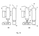
- the device basically has a coating device 2 and a cutting device 3. With the help of Coating device 2 becomes metallic or metal-bound Melted powder and applied in layers. In this way, the workpiece is built up 1 layer by layer. To the shape accuracy and the surface quality of the To improve workpiece 1, the individual layers, as will be explained in more detail later, by the cutting device 3 individually or combined reworked.
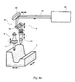
- the coating device 2 has a laser unit a laser beam focusing head 4 and a powder feeder with a powder head 5, which contains the metal Powder feeds into a melting area of the laser beam the powder, as will be explained in more detail later, in Layers on a workpiece substrate or on already applied ones Melting layers.
- the laser beam focusing head 4 and the powder head 5 arranged coaxially with each other and form an integral coating unit that is generally designated by reference number 6.
- the cutting device 3 has a cutting head 7, in the various milling and grinding tools, e.g. Forehead-, End mills and ball end mills or grinding wheels and pins, are clamped to the surface of the applied layers postprocess.
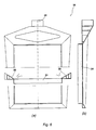
- the cutting head 7 and the coating unit 6 are together on a holding device, generally designated by the reference number 8 is referred to, stored and are by this guided relative to the workpiece 1.
- the holding device 8 is relative to a work table 9 on which the workpiece 1 rests, adjustable along three axes.
- This is a Portal storage device 10 provided on the holding device 8 is stored.
- the portal storage device 10 has a pair of vertical struts lla and llb, to which the Workbench 9 is relatively displaceable along an x-axis and movable by a drive, not shown is.
- a traverse on the two vertical struts lla and llb 12 mounted on which in turn a vertical guide 13 is slidably supported along a y-axis, which by a drive, also not shown, can be moved.
- the holding device 8 is fastened to a slide 14, the along the vertical guide 13 in the direction of a z-axis is slidably mounted and also not by one shown drive is movable.
- the holding device 8 for building up a layer and post-processing them in the x and y directions relative to to move the workpiece 1.
- For building another one Layer is the holding device 8 along the z-axis adjusted above.
- the holding device 8 relative to the work table 9 along three axes is adjustable, it is also possible to use the holding device 8 and the work table 9 five-axis relative to each other adjustable to store more complicated workpiece geometries easier to manufacture.
- the coating unit is 6 with the laser beam focusing head 4 and the powder head 5 by the holding device 8 relative to the cutting head 7 adjustable along an axis z2 and by a Movable drive, not shown.
- the Holding device 8 as can be seen in FIGS. 3 and 4 adjustable holding part 14, which on a holding frame 15th the holding device 8 is slidably mounted.
- the holding part 14 is a transmission member with this 16 connected, the part of a drive such as a hydraulic piston-cylinder unit with which the coating unit 6 relative to the cutting head 7 is proceeded.
- the coating unit 6 can thereby be moved up from a collision area to the coating unit 6 to bring them to a safe distance, if with the cutting head 7 an applied layer of Workpiece 1 is reworked.
- the laser beam focusing head 4 and the powder head 5 through a hollow cylindrical connecting part 16 connected to each other, such that the laser beam focusing head 4 and the powder head 5 coaxial with each other are arranged.
- a leaving the focusing head 4 Laser beam 17 is through the hollow cylindrical connecting part 16 through and through a central recess 18 in passed through the powder head 5 onto the workpiece 1.
- the Powder head 5 has connection sections on a peripheral side 19 on which the powder head with lines one does not shown powder conveyor is connected.
- the connection sections 19 of the powder head 5 are with powder channels 20, which are formed in the powder head 5, connected.
- the powder head has 5 protective gas channels, with corresponding Connection sections connected to the powder head 5 are (but not shown) for the reflow process Add protective gas and bundle the powder jet.
- the coaxial feeding of the powder into the melting range of the Laser beam enables stable melting of the powder, even if, as will be described in more detail later tracks with a relatively small thickness and width in one Range of about 0.1 mm or 0.3 to 0.4 mm can be applied.
- the powder head 5 is relative to that Laser beam focusing head adjustable in the direction of the laser beam.
- the connecting part 16 has a fine adjustment device 21 on the powder head 5 along the Axis z2 'away from the focusing head 4 and moved towards it.
- the Fine adjustment device 21 has a threaded connection which is a first connecting portion 16a relative to one second connecting section 16b is adjustable so that adjust the total length of the connecting part 16 leaves. This can be done by manually turning the connecting section 16a take place.
- a numerically controlled Provide drive through which the powder head 5 automatically adjustable relative to the laser beam focusing head 4 is.
- the adjustability between the powder head 5 and the laser beam focusing head 4 also allows you to trace the powder to melt different widths. For a bigger one
- the laser beam is defocused, to increase the melting range.
- the laser beam focusing head 4 along the z2 axis relative moved up to the holding device 8 away from the workpiece 1, so that the distance between the laser beam focusing head 4 and the workpiece 1 enlarged.
- the powder head 5 relative to the focusing head 4 the fine adjustment device 21 down along the axis z2 ' moved to compensate for the adjustment of the focusing head 4 and the powder exactly in the melting range of the laser beam 17 feed. This way layers can with high order rates and at the same time with one high contour accuracy, as will be explained later will be built.
- the laser beam focusing head 4 is connected to an optical fiber cable 22, through which the laser beam is guided from a laser source (not shown) to the laser beam focusing head 4.
- An Nd-YAG laser is preferably provided as the laser source.
- the coating unit 6 can be moved in a simple manner without the need for complex deflecting mirror devices.
- the guidance of the laser beam through deflecting mirror devices should preferably be used in conjunction with a CO 2 laser as the laser source.
- the kinematics of the holding device 8 for the cutting head 7 and the coating unit 6 is in the schematic 7 clarifies the illustration.
- the cutting head 7 and the coating unit 6, which are axially offset from one another are arranged together are perpendicular to the work table 9 adjustable to match the one already applied Layers and a layer thickness to be set the structure of a workpiece from bottom to top.
- the coating unit 6 as a whole is relative to the cutting head 7 adjustable.
- the powder head 5 again adjustable relative to the laser beam focusing head 4.
- Various milling and grinding tools 23 can be clamped in the machining head 7, which are driven by a drive of the machining device 3, not shown, which preferably also has an electrical high-speed spindle, also not shown, at a speed in the range from 10 ⁇ 10 3 rpm - 60 ⁇ 10 3 rpm can be driven.
- very fine milling or grinding tools can also be used to finely rework the surface of the melted layers, especially on their contour side.
- a not insignificant aspect in the litigation for the Layer-by-layer construction of the workpiece 1 by melting the Powder is the temperature of the workpiece 1.
- a cooling device is provided which holds the workpiece 1 cools and essentially at a constant temperature holds.
- Cooling plate 24 is provided, on which the workpiece 1 rests.
- a plurality of coolant channels 25, circulated through the coolant is a temperature measuring system not shown in the figures, which preferably has a pyrometer. This temperature measurement system detects one after machining a layer Surface temperature of the workpiece 1.
- the further structure of the workpiece is only continued when the detected Temperature does not exceed a specified value.
- this temperature is between 20 ° and 100 ° C.
- a suction device 26 is provided, the excess Powder or residues generated by the melting process sucks.
- the suction device 26 has a suction frame 27, which extends around the cooling plate 24.
- the suction frame 27 is essentially formed by a hollow profile, which has a triangular cross section.
- the suction frame has a peripheral edge of the cooling plate 24 27 a circumferential suction opening through which excess Powder from the surface of the cooling plate 24 to the inside of the suction frame 27 is sucked in.
- the suction frame 27 is arranged such that a frame surface 29 of starting from the circumferential edge of the cooling plate 24 extends obliquely outwards and inclined upwards, so that excess powder on the frame surface 29 back on the cooling plate 24 slides and through the suction opening 28 in the inside of the suction frame 27 is sucked in.
- a suction pipe connection 30 On one side of the suction frame 27 is a suction pipe connection 30 provided to which a suction pipe of the suction device 28 is connected.
- the suction frame 27 has a changing cross-sectional area on from the suction pipe connection 30 to the, based on the suction pipe connection 30, most distant portion of the suction frame 27 continuously decreases to in every area of the Suction frame 27 for the suction of powder particles to achieve the necessary flow rate.
- the excess powder and other residue particles can for example during the laser coating process and / or after the laser coating process and / or during can be suctioned off during machining. Since the vacuumed Powder with unmelted grains, oxides or chips is affected, there is a processing device in the suction device provided, for example, a cyclone separator, which separates the impurities and / or has a fine dust filter, the fine dust from the excess Powder separates. The recovered powder can then returned to the powder feeder become.
- a processing device in the suction device provided, for example, a cyclone separator, which separates the impurities and / or has a fine dust filter, the fine dust from the excess Powder separates.
- the recovered powder can then returned to the powder feeder become.
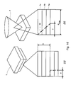
- the deflecting mirror device 31 a first deflecting mirror 53 and a second deflecting mirror 54 on which the laser beam to the focusing head 4 lead, according to the embodiment shown Focusing mirror 44 has.
- FIG. 8b Another embodiment with a deflecting mirror device 31 is shown in FIG. 8b.
- the deflecting mirror device 31 has only a first deflecting mirror 53, which directs the laser beam 17 emerging from the laser source 51 directly to the focusing head 4, which according to this exemplary embodiment has a focusing lens 45.
- a CO 2 laser is provided as laser source 51.
- the workpiece can be along an x and y axis be slidable so that the focusing head 4, the powder head 5 and the cutting head 7 only in the direction of one z-axis are displaceable.
- the powder head 5 is relative to the focusing head 4, i.e. relative to the focus mirror 44 or the focusing lens 45 along the z-axis adjustable.
- the deflecting mirror 53 requires in this embodiment no mobility and is rigidly mounted.
- the workpiece can only be moved along the x direction be, then the focusing head 4, the powder head 5 and the cutting head 7 both along the y axis and are also displaceable on the z-axis.
- the deflecting mirror 53 is also displaceable along the y-axis.
- the powder head 5 adjustable along the z-axis is.
- This adjustability of the powder head, relatively to the focusing head 4 is necessary to feed the powder always exactly in the melting range of the laser beam 17 judge.
- a focusing mirror is sufficient 44 or a focusing lens 45 to provide the are each rigidly mounted.
- 8c is an embodiment of the invention Device similar to that described with reference to Figures 1-7 Embodiment shown.
- laser source 51 an Nd-YAG laser is provided, from which a laser beam emerges by means of an optical fiber cable 22 to the laser beam focusing head 4 is performed.
- different axis distributions are possible.
- the workpiece 1 along the x-axis and Y-axis can be moved while the focusing head 4 and the powder head 5 each (and relative to each other) along the z-axis are slidably mounted.
- the cutting head 7 is also movably supported along the z-axis.
- the cutting head 7 the powder head 5 and the laser beam focusing head 4 both along the y axis as well movable on the z-axis.
- the workpiece 1 along the three axes x, y and z be movable, so that in this embodiment only the powder head 5 can be moved along the z-axis.
- the laser beam focusing head 4 and the machining head 7 can be rigidly mounted.
- the cutting head 7 the Laser beam focusing head 4 and the powder head 5 along the x-axis, the y-axis and the z-axis can be moved. All embodiments common is that the powder head 5 relative to the laser beam focusing head 4, namely along the z-axis, is movable.
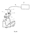
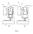
- FIG. 9 Another preferred embodiment of the invention is shown in Fig. 9.
- the device shown therein differs different from the previously described embodiments essentially in that the cutting head 7 and the coating unit 6 is not axially offset from one another are simultaneously mounted on a holding device, but that the holding device in this embodiment is generally designated by reference number 34, has a tool changing device 33, optionally the coating unit 6 or the cutting head 7 is clamped can be.
- the tool changing device 33 and are the coating unit 6 or the machining head 7 designed such that the cutting head 7 coaxial arranged to the laser beam focusing head 4 or the powder head 5 is when this is in the tool changing device 33 are clamped.
- the coaxial arrangement of the coating unit 6 and the cutting head 7 facilitated the machining of the melted layers and in particular reduces the programming effort for the Machining. It is also particularly advantageous that the available work area is as good as possible is exploited
- the cutting device 3 has a compressed air spindle 36 for driving the milling or grinding tool 23.
- Components or components of this embodiment which in essentially correspond to those of the first exemplary embodiment, are designated by the same reference numbers. Another Explanation does not appear to be necessary.
- a distance sensor has the distance from the top of the last applied layer from a reference point. This measuring process can be carried out continuously during machining or selectively after machining be performed. If the target height is not reached, there is a new coating process according to the Geometry of the last layer applied. If the one to be created Geometry, i.e. the target height after another or not achieved after repeated coating processes alarm is triggered and the manufacturing process is stopped, in order to first correct the corresponding causes of errors, before the manufacturing process is started again.
- Each of the devices described above according to the different Embodiments of the invention also have an electronic control device for controlling the coating device and the cutting device.
- the control device has an interface to CAD geometry data a CAD model of the workpiece to be manufactured, generated on a CAD unit.
- the controller generates based on this CAD geometry data and other manually entered data, are determined by the options in process control, independently a machining program to control the Coating device and the cutting device. This makes the production of the workpiece to a high degree automated.
- the NC data can be used for control the coating device and the cutting device generated in two different ways.
- CAD unit Corresponding a first embodiment by means of CAD unit generated two different CAD models, one of which one of the target geometry of the workpiece to be manufactured corresponds and used for machining post-processing is and a second the workpiece to be manufactured with larger Corresponds to dimensions that use for the coating process becomes.
- only one generated only CAD model whereby when creating the NC data for controlling the coating device, i.e. for the coating process, a fictitious tool diameter correction is defined so that a wider one Layer is applied. During post-processing the actual tool is then defined so that the Target geometry is reached.
- the workpiece is out Layers 1a, 1b ... 1n built up by using the coating unit 6
- Metallic powder melted in layers becomes.
- the layers 1a, 1b to 1n are each reworked individually or in groups of several at the same time.
- This layer-by-post processing reduces the Milling or grinding on a two-dimensional machining with constant cutting conditions, what the Postprocessing much easier and especially the Programming effort considerably reduced. Furthermore the risk of collision is reduced and the processing of thin and slim deep recesses avoided.
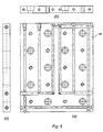
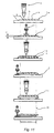
- a single layer is created as seen in Fig. 11 by melting several tracks side by side.
- the number of tracks varies depending on the one to be produced Wall thickness of the workpiece 1 at the location of this layer, i.e. depending on the width 1 of the layer to be produced and reduced in the borderline case to a single track.
- a Laser power which is less than 1 kW
- a width b im Range of 0.1 mm - 1 mm preferably in the range of 0.2 mm - 0.5 mm
- a thickness d in the range of 0.05 mm - 0.5 mm, preferably applied in the range of 0.05 mm - 0.2 mm.
- the first layer 1a After the first layer 1a has been applied, it is melted another layer, the first layer 1a on its Top face 1 'milled, in such a way that layer 1a defines one Layer thickness d has. For this, a rough milling tool used to achieve high cutting performance. While before melting another layer the top 1 'of the first layer 1a is processed, the remains Layer 1a on its contour sides 1 "unprocessed, so that the first layer still protrudes beyond a target contour 38.
- the contour side 1 "of the layers is finely machined with a fine milling or grinding tool in order to achieve high dimensional accuracy and surface quality on the contour side 1".
- the fine milling or grinding tool is rotated at a speed in the range from 10 x 10 3 to 60 x 10 3 .
- the top is the second layer, while the Contour side of the second layer 1b remains unprocessed and is only reworked when the third layer 1c has melted.
- the penultimate Layer or more applied before the last layer Layers, which is particularly important at the start of the process
- a single layer in Traces ⁇ of different geometry applied. While in Edge zones A of a layer 1a have tracks ⁇ with a relatively small number Width b and small thickness d are applied in a core zone B of layer 1a tracks ⁇ with relatively larger ones Width b and greater thickness d applied. You can also Layers of different thickness can be applied.
- the layer 1 a in its Edge zones are first machined to a defined one Achieve edge zone geometry before in a following Step onto the reworked contour area tracks ⁇ small thickness and width are applied.
- a layer 1a can initially also in an edge zone with traces ⁇ of small thickness and width be built up before in a subsequent step Core zone B with larger traces ⁇ is generated. In a subsequent one Then the contour area and the Machined top of the applied layer.
- FIG. 12d shows an embodiment of the method shown where a layer is uniform with larger traces ⁇ is built up, with the contour area and the top is formed solely by machining post-processing.
- the laser beam diameter is used for different application rates changed in the melting range in which the laser beam focusing head 4, as shown in Fig. 13, relative to that Workpiece 1 is moved so that the distance to the workpiece 1 changes.
- the Laser beam focusing head 4 moved away from the workpiece 1.
- the powder head 5 must be relative to the focusing head 4 can be adjusted along the direction of the laser beam feed the powder into the melting range of the laser beam 17, i.e. the movement of the laser beam focusing head 4 must can be compensated by a counter movement of the powder head 5.
- layers and traces applied in a layer of different materials. Basically, metallic or metal-bound Ceramic materials melted in powder form. While in claimed edge zones A of the workpiece 1 layers 1n and Traces ⁇ in a layer 1n made of hard, wear-resistant Material is applied in core zones B of the workpiece a soft tough material melted so that the Workpiece properties can be optimized.
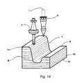
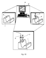
- 15 shows the method steps leading to the partial construction a mold, i.e. especially for repairs of the mold, according to a preferred embodiment of the procedure.
- the first step is with the help of the CAD unit 37 a geometrically regular Area R defined in the workpiece 1, which is the defective Digit S contains.
- the geometrically regular area R is by means of the cutting device 3 from the Workpiece 1 milled or ground to replace the damaged one Area S, which is an irregular and indefinite Form has to create an area of known geometry.
- the workpiece 1 is in the area of the recess through the geometric regular area R is formed locally rebuilt by melting metal-containing powder in layers becomes.
- the procedural strategies described above are matched according to the workpiece.
- FIG. 16 illustrates the production of undercut workpieces 1 according to a preferred embodiment of the invention Method, the workpiece 1 according to FIG. 16a step-shaped and undercut conically according to FIG. 16b is.
- n layers are first melted, the individual layers being machined only on an upper side onto which a further layer is melted.
- the contour sides of the layers initially remain unprocessed.
- the number n of layers is melted in accordance with a maximum width or a maximum diameter d max of the target contour to be produced.
- the layers 1a, 1b and 1c are machined on their contour side in order to produce the desired contour 38 of the undercut.
- the maximum width that can be produced without collision with the milling or grinding tool is identified by the letter v.
- Procedure and the associated device are characterized by fast and very precise production from molds, which are partially matched by the use of materials has optimized tool properties, whereby in particular the high level of automation and the low level Programming effort is an advantage.
Claims (44)
- Procédé de fabrication de pièces métalliques, notamment d'outils de formage, dans lequel une poudre métallique est déposée couche par couche par fusion à l'aide d'un rayon laser sur une zone de fusion du rayon laser, et dans lequel les couches appliquées sont usinées par enlèvement de copeaux, caractérisé en ce que la poudre est amenée dans la zone de fusion de façon coaxiale par rapport au rayon laser (17), et que les différentes couches (1a, 1b...1n) sont déposées par bandes (α, β) d'une largeur (b) comprise entre 0,1 mm et 1 mm et d'une épaisseur (d) comprise entre 0,05 mm et 0,5 mm.
- Procédé selon la revendication 1, caractérisé en ce que les bandes (α, β) sont déposées et ont une largeur (b) comprise entre 0,2 mm et 0,5 mm et une épaisseur (d) comprise entre 0,05 et 0,2 mm.
- Procédé selon la revendication 1 ou 2, caractérisé en ce qu'une seule couche (1a, 1b, 1n) est déposée par bandes (α, β) de géométries différentes.
- Procédé selon la revendication 3, caractérisé en ce que dans les zones de bordure (A) d'une couche (1a), des bandes (β) d'une largeur (b) et d'une épaisseur (d) relativement faibles sont déposées, tandis que sur une zone centrale de la couche (1a) des bandes (α) d'une largeur (b) et d'une épaisseur (d) relativement plus importantes sont déposées.
- Procédé selon au moins l'une des revendications 1 à 4, caractérisé en ce que les bandes (α) sont déposées sur des zones centrales (B) de différentes couches (1a, 1b, 1n) dans des directions différentes.
- Procédé selon au moins l'une des revendications 1 à 5, caractérisé en ce que la poudre est appliquée par fusion avec une puissance de laser inférieure ou égale à 1 kW.
- Procédé selon au moins l'une des revendications 1 à 6, caractérisé en ce que l'on utilise un laser YAG dopé au néodyme.
- Procédé selon au moins l'une des revendications 1 à 6, caractérisé en ce que l'on utilise un laser à Co2.
- Procédé selon au moins l'une des revendications 1 à 8, caractérisé en ce que les couches (1a, 1b, 1n) et/ou les bandes (α, β) sont déposées en une couche à base de matières différentes.
- Procédé selon la revendication 9, caractérisé en ce que sur des zones de bordure (A) sollicitées de la pièce (1), des couches (1n) et/ou des bandes (β) sont déposées en une couche (1n) d'une matière dure résistante à l'usure, tandis que sur des zones centrales (B) de la pièce (1), des couches (1a, 1b) et/ou des bandes (α) sont déposées en une couche de matière douce.
- Procédé selon au moins l'une des revendications 1 à 10, caractérisé en ce que les couches déposées (1a, 1b, 1n) sont respectivement usinées de façon individuelle.
- Procédé selon la revendication 11, caractérisé en ce que la couche (1a, 1b) respectivement déposée en dernier est tournée transversalement avant le dépôt d'une autre couche (1b, 1c) sur une face supérieure (1') sur laquelle est déposée la couche suivante, tandis qu'une face de contour (1") de la dernière couche déposée reste sans usinage avant le dépôt de la couche suivante.
- Procédé selon la revendication 11 ou 12, caractérisé en ce que respectivement l'avant-dernière couche (1a, 1b) ou plusieurs couches déposées avant la dernière couche (1c) sont usinées sur une face de contour (1").
- Procédé selon au moins l'une des revendications 1 à 13, caractérisé en ce que les couches (1a, 1b, 1n) sont usinées par fraisage et/ou meulage.
- Procédé selon la revendication 14, caractérisé en ce que les faces de contour (1") des couches (1a, 1b, 1n) sont usinées à l'aide d'outils de fraisage fins, tandis que la face supérieure (1') de la couche respectivement déposée en dernier est usinée à l'aide d'outils de fraisage grossier.
- Procédé selon au moins l'une des revendications 1 à 15, caractérisé en ce que les couches (1a, 1b, 1n) subissent un usinage fin à l'aide d'outils de fraisage fins ou d'outils de meulage (23) à une vitesse de rotation comprise entre 10 x 103 tr/min. et 60 x 103 tr/min.
- Procédé selon au moins l'une des revendications 1 à 16, caractérisé en ce que la couche (1a) déposée en dernier est usinée dans une zone de contour de telle sorte que la zone de contour soit obtenue dans une forme prédéterminée et que dans une étape suivante, des bandes (β) de faible épaisseurs (d) et largeur (b) soient déposées sur la zone de contour usinée.
- Procédé selon au moins l'une des revendications 1 à 17, caractérisé en ce que la pièce (1) est refroidie pendant le traitement laser et/ou l'enlèvement de copeaux.
- Procédé selon au moins l'une des revendications 1 à 18, caractérisé en ce que la poudre non fondue est expulsée et/ou aspirée d'une zone de travail.
- Dispositif de fabrication dé pièces métalliques, notamment d'outils de formage, comprenant un dispositif de revêtement présentant une unité laser avec une tête de focalisation du rayon laser, et un dispositif d'alimentation en poudre pour alimenter une zone de fusion du rayon laser avec de la poudre métallique, et un dispositif d'enlèvement de copeaux, notamment pour la mise en oeuvre du procédé selon la revendication 1, caractérisé en ce que le dispositif d'alimentation en poudre présente une tête à poudre (5) disposée coaxialement par rapport à la tête de focalisation du rayon laser et mobile en direction du rayon laser (17) relativement par rapport à la tête de focalisation (4) du rayon laser pour disposer par fusion la poudre amenée en bandes d'épaisseurs et/ou largeurs différentes, l'amenée coaxiale de la poudre dans la zone de fusion du rayon laser permettant une fusion stable de la poudre pour disposer des bandes d'une largeur (b) comprise entre 0,1 mm et 1 mm et d'une épaisseur (d) comprise entre 0,05 mm et 0,5 mm.
- Dispositif selon la revendication 20, caractérisé en ce que la tête de focalisation (4) du rayon laser et la tête à poudre (5) constituent une unité de revêtement (6) intégrale.
- Dispositif selon la revendication 20 ou 21, caractérisé en ce que le dispositif d'enlèvement de copeaux (3) présente une tête d'enlèvement (7) comprenant un outil de fraisage ou de meulage (23)
- Dispositif selon la revendication 21 ou 22, caractérisé en ce que la tête d'enlèvement (7) et l'unité de revêtement (6) sont logées sur un dispositif de maintien (8, 34).
- Dispositif selon la revendication 23, caractérisé en ce que le dispositif de maintien (34) présente un dispositif de changement d'outil (33) permettant de recevoir au choix la tête d'enlèvement (7) et l'unité de revêtement (6).
- Dispositif selon la revendication 24, caractérisé en ce que la tête d'enlèvement (7) et l'unité de revêtement (6) sont disposées de façon coaxiale l'une par rapport à l'autre.
- Dispositif selon au moins l'une des revendications 21 à 23, caractérisé en ce que la tête d'enlèvement (7) et l'unité de revêtement (6) sont disposées de façon décalée l'une par rapport à l'autre.
- Dispositif selon la revendication 26, caractérisé en ce que la tête d'enlèvement (7) est mobile relativement par rapport à l'unité de revêtement (6) dans une direction verticale par rapport à une table de travail (9).
- Dispositif selon au moins l'une des revendications 23 à 27, caractérisé en ce que le dispositif de maintien (8, 34) et la table de travail (9) sont mobiles relativement l'un par rapport à l'autre le long de trois axes (xyz).
- Dispositif selon au moins l'une des revendications 23 à 27, caractérisé en ce que le dispositif de maintien (8, 34) et la table de travail (9) sont mobiles relativement l'un par rapport à l'autre selon cinq axes.
- Dispositif selon la revendication 28 ou 29, caractérisé en ce que respectivement des entraínements d'avance à commande numérique sont prévus pour le déplacement relatif l'un par rapport à l'autre du dispositif de maintien (8) et de la table de travail (9).
- Dispositif selon au moins l'une des revendications 20 à 30, caractérisé en ce qu'un entraínement à commande numérique est prévu pour le déplacement relatif l'une par rapport à l'autre de la tête de focalisation (4) du rayon laser et de la tête à poudre (5).
- Dispositif selon au moins l'une des revendications 20 à 31, caractérisé en ce qu'un câble à guides d'ondes lumineuses (22) est relié à la tête de focalisation (4) du rayon laser.
- Dispositif selon au moins l'une des revendications 20 à 31, caractérisé en ce qu'un dispositif à miroir de renvoi (50) est prévu.
- Dispositif selon au moins l'une des revendications 20 à 33, caractérisé en ce qu'un laser YAG dopé au néodyme est prévu en tant que source laser.
- Dispositif selon la revendication 33, caractérisé en ce qu'un laser à Co2 est prévu en tant que source laser.
- Dispositif selon au moins l'une des revendications 21 à 35, caractérisé en ce qu'un dispositif d'entraínement est associé à la tête d'enlèvement (7) pour entraíner l'outil de fraisage ou de meulage (23).
- Dispositif selon la revendication 36, caractérisé en ce que l'outil de fraisage ou de meulage (23) peut être entraíné à une vitesse comprise entre 10 x 103 tr/min. et 60 x 103 tr/min.
- Dispositif selon la revendication 36 ou 37, caractérisé en ce que le dispositif d'entraínement présente une broche électrique à grande vitesse.
- Dispositif selon au moins l'une des revendications 20 à 38, caractérisé en ce qu'une table de travail (9) présente un dispositif de refroidissement (24).
- Dispositif selon la revendication 39, caractérisé en ce que le dispositif de refroidissement présente des canaux à réfrigérant (25) formés dans la table de travail (9).
- Dispositif selon au moins l'une des revendications 20 à 40, caractérisé en ce qu'un dispositif d'aspiration de poudre (26) est prévu sur une zone de travail de l'unité de revêtement (6).
- Dispositif selon au moins l'une des revendications 20 à 41, caractérisé en ce qu'un dispositif de commande électronique est prévu pour la commande du dispositif de revêtement (2) et du dispositif d'enlèvement (3).
- Dispositif selon la revendication 42, caractérisé en ce que le dispositif de commande présente une interface pouvant être reliée à une unité CAO (37).
- Dispositif selon la revendication 43, caractérisé en ce que le dispositif de commande génère un programme d'usinage sur la base de données géométriques CAO et de données saisies manuellement pour la commande du dispositif de revêtement (2) et du dispositif d'enlèvement (3).
Applications Claiming Priority (3)
| Application Number | Priority Date | Filing Date | Title |
|---|---|---|---|
| DE19533960A DE19533960C2 (de) | 1995-09-13 | 1995-09-13 | Verfahren und Vorrichtung zur Herstellung von metallischen Werkstücken |
| DE19533960 | 1995-09-13 | ||
| PCT/EP1996/003231 WO1997010067A1 (fr) | 1995-09-13 | 1996-07-22 | Procede et dispositif de production de pieces metalliques |
Publications (2)
| Publication Number | Publication Date |
|---|---|
| EP0790875A1 EP0790875A1 (fr) | 1997-08-27 |
| EP0790875B1 true EP0790875B1 (fr) | 2000-11-02 |
Family
ID=7772075
Family Applications (1)
| Application Number | Title | Priority Date | Filing Date |
|---|---|---|---|
| EP96927576A Expired - Lifetime EP0790875B1 (fr) | 1995-09-13 | 1996-07-22 | Procede et dispositif de production de pieces metalliques |
Country Status (4)
| Country | Link |
|---|---|
| EP (1) | EP0790875B1 (fr) |
| AT (1) | ATE197259T1 (fr) |
| DE (2) | DE19533960C2 (fr) |
| WO (1) | WO1997010067A1 (fr) |
Cited By (4)
| Publication number | Priority date | Publication date | Assignee | Title |
|---|---|---|---|---|
| EP1887107A3 (fr) * | 2006-08-12 | 2008-09-17 | Rolls-Royce plc | Méthode de formation dýun composant sur un substrat |
| KR20160064377A (ko) * | 2014-11-27 | 2016-06-08 | 한국생산기술연구원 | 3차원 메탈프린터를 이용한 다공성 패드 제작방법 |
| CN107363259A (zh) * | 2016-03-23 | 2017-11-21 | 沙迪克株式会社 | 层叠造型装置 |
| FR3060426A1 (fr) * | 2016-12-19 | 2018-06-22 | Peugeot Citroen Automobiles Sa | Procede d’emboutissage et decoupe en serie |
Families Citing this family (71)
| Publication number | Priority date | Publication date | Assignee | Title |
|---|---|---|---|---|
| DE19701078C1 (de) * | 1997-01-15 | 1998-02-05 | Ikm Inst Fuer Kunststoffe Im M | Verfahren zur Herstellung von dreidimensionalen, für die Formgebung von thermoplastifiziertem Kunststoff bestimmten Werkzeugen |
| DE19817091C2 (de) * | 1998-04-17 | 2001-04-05 | Nu Tech Gmbh | Verfahren zum Einlegieren von pulverförmigen Zusatzstoffen und Vorrichtung zur Durchführung des Verfahrens |
| DE19841892C1 (de) * | 1998-09-11 | 1999-09-30 | Fraunhofer Ges Forschung | Verfahren und Vorrichtung zur Herstellung von Werkstücken |
| DE19907105A1 (de) | 1999-02-19 | 2000-08-31 | Volkswagen Ag | Verfahren und Vorrichtung zum Herstellen von verschleißfesten, tribologischen Zylinderlaufflächen |
| US6520996B1 (en) | 1999-06-04 | 2003-02-18 | Depuy Acromed, Incorporated | Orthopedic implant |
| DE19929333C1 (de) * | 1999-06-26 | 2000-12-07 | Continental Ag | Verfahren zum Herstellen einer Vulkanisationsform für Fahrzeugreifen und Vulkanisationsform für Fahrzeugreifen |
| US6396025B1 (en) | 1999-07-01 | 2002-05-28 | Aeromet Corporation | Powder feed nozzle for laser welding |
| DE19935274C1 (de) * | 1999-07-27 | 2001-01-25 | Fraunhofer Ges Forschung | Vorrichtung und Verfahren zur Herstellung von Bauteilen aus einer Werkstoffkombination |
| DE19937260B4 (de) | 1999-08-06 | 2006-07-27 | Eos Gmbh Electro Optical Systems | Verfahren und Vorrichtung zum Herstellen eines dreidimensionalen Objekts |
| DE19949972C1 (de) * | 1999-10-11 | 2001-02-08 | Fraunhofer Ges Forschung | Verfahren zur Herstellung von Formkörpern oder zum Auftragen von Beschichtungen |
| DE10007962C1 (de) * | 2000-02-22 | 2001-07-26 | Werkzeugbau Siegfried Hofmann | Verfahren zur Herstellung von Spritzguß- oder Druckgußformen |
| DE10009133A1 (de) * | 2000-02-26 | 2001-08-30 | Volkswagen Ag | Verfahren zum Laserbeschichten einer Oberfläche |
| CA2370657A1 (fr) * | 2000-02-28 | 2001-09-07 | Vaw Aluminium Ag | Procede de production d'un composant cylindrique, partiellement cylindrique ou cylindrique creux dont la surface est alliee, et dispositif pour la mise en oeuvre de ce procede |
| AU2001275253A1 (en) * | 2000-06-05 | 2001-12-17 | Laser Fire | Orthopedic implant and method of making metal articles |
| DE10065960C5 (de) * | 2000-06-07 | 2005-10-06 | (bu:st) GmbH Beratungsunternehmen für Systeme und Technologien | Verfahren zur Herstellung eines Werkstückes mit exakter Geometrie |
| AT4665U1 (de) | 2000-07-14 | 2001-10-25 | Plansee Tizit Ag | Verfahren zum pressen einer schneidplatte |
| DE10047614C2 (de) * | 2000-09-26 | 2003-03-27 | Generis Gmbh | Vorrichtung zum schichtweisen Aufbau von Modellen |
| JP3446733B2 (ja) * | 2000-10-05 | 2003-09-16 | 松下電工株式会社 | 三次元形状造形物の製造方法及びその装置 |
| DE10053742C5 (de) * | 2000-10-30 | 2006-06-08 | Concept Laser Gmbh | Vorrichtung zum Sintern, Abtragen und/oder Beschriften mittels elektromagnetischer gebündelter Strahlung sowie Verfahren zum Betrieb der Vorrichtung |
| GB0028557D0 (en) * | 2000-11-23 | 2001-01-10 | Innovative Materials Proc Tech | Fabrication method and apparatus |
| DE10058748C1 (de) | 2000-11-27 | 2002-07-25 | Markus Dirscherl | Verfahren zur Herstellung eines Bauteils sowie Vorrichtung zur Durchführung des Verfahrens |
| EP1234625A1 (fr) * | 2001-02-21 | 2002-08-28 | Trumpf Werkzeugmaschinen GmbH + Co. KG | Procédé et dispositif pour fabriquer un article par frittage selective au laser |
| DE10124795A1 (de) | 2001-05-21 | 2002-12-12 | Bu St Gmbh Beratungsunternehme | Vorrichtung und Verfahren zur Herstellung eines Werkstücks mit exakter Geometrie |
| DE10157647C5 (de) * | 2001-11-26 | 2012-03-08 | Cl Schutzrechtsverwaltungs Gmbh | Verfahren zur Herstellung von dreidimensionalen Werkstücken in einer Laser-Materialbearbeitungsanlage oder einer Stereolitographieanlage |
| DE10158169B4 (de) * | 2001-11-28 | 2007-02-08 | Cl Schutzrechtsverwaltungs Gmbh | Vorrichtung zur Herstellung und/oder Bearbeitung von Bauteilen aus Pulverteilchen |
| DE60237139D1 (de) * | 2002-03-26 | 2010-09-09 | Panasonic Elec Works Co Ltd | Verfahren zur Herstellung eines gesinterten Formkörpers durch selektives Laser-Sintern |
| US20060006157A1 (en) * | 2004-07-09 | 2006-01-12 | Ingersoll Machine Tools, Inc. | Method and apparatus for repairing or building up surfaces on a workpiece while the workpiece is mounted on a machine tool |
| DE102004042492A1 (de) | 2004-08-31 | 2006-03-09 | WINKLER + DüNNEBIER AG | Verfahren und Vorrichtung zur Herstellung einer Schneid- oder Prägewalze mittels Laserauftragsschweißen |
| DE102005007792B4 (de) * | 2005-02-14 | 2013-03-07 | Lim Laserinstitut Mittelsachsen Gmbh | Verfahren und Einrichtung zum Auftragsschweissen von Schichten aus Partikeln mit einer Korngrösse kleiner 20 μm auf Substrate |
| GB0509263D0 (en) * | 2005-05-06 | 2005-06-15 | Rolls Royce Plc | Component fabrication |
| FR2896176B1 (fr) * | 2006-01-16 | 2009-12-04 | Snecma | Procede de fabrication d'un objet par projection laser de poudre metallique, tel qu'une pale de turbomachine |
| DE102008012063B4 (de) * | 2008-02-29 | 2016-01-07 | Cl Schutzrechtsverwaltungs Gmbh | Verfahren zur Herstellung eines Hybridformteils |
| EP2280801B1 (fr) | 2008-05-29 | 2015-02-25 | Siemens Aktiengesellschaft | Procédé de soudage de pièces d'usinage en alliages superréfractaires |
| DE102008031926A1 (de) * | 2008-07-08 | 2010-01-14 | Bego Medical Gmbh | Verfahren zum schichtweisen Herstellen stark geneigter Flächen |
| DE102008031925B4 (de) * | 2008-07-08 | 2018-01-18 | Bego Medical Gmbh | Duales Herstellungsverfahren für Kleinserienprodukte |
| US10000021B2 (en) | 2009-06-23 | 2018-06-19 | Panasonic Intellectual Property Management Co., Ltd. | Method for manufacturing three-dimensional shaped object and three-dimensional shaped object obtained by the same |
| DE102009033684A1 (de) * | 2009-07-17 | 2010-11-18 | Mtu Aero Engines Gmbh | Schleifsystem |
| DE102009038165A1 (de) * | 2009-08-20 | 2011-02-24 | Fockele, Matthias, Dr. | Vorrichtung zur Herstellung von Formkörpern durch schichtweises Aufbauen aus Werkstoffpulver |
| SE535361C2 (sv) | 2010-11-10 | 2012-07-10 | Biomain Ab | Dentalbryggor och superstrukturer, samt metoder för att tillverka dessa |
| FR2983424B1 (fr) * | 2011-12-02 | 2014-09-19 | Nantes Ecole Centrale | Procede et dispositif d'usinage par addition de matiere et mise en forme combinees |
| DE102012004213A1 (de) * | 2012-03-06 | 2013-09-12 | Voxeljet Technology Gmbh | Verfahren und Vorrichtung zum Herstellen dreidimensionaler Modelle |
| EP2849672B1 (fr) | 2012-05-10 | 2019-10-16 | Renishaw Plc. | Procédé de fabrication d'un article |
| WO2013167903A1 (fr) | 2012-05-10 | 2013-11-14 | Renishaw Plc | Procédé de fabrication d'un article |
| GB201212629D0 (en) | 2012-07-16 | 2012-08-29 | Prec Engineering Technologies Ltd | A machine tool |
| US9751260B2 (en) | 2013-07-24 | 2017-09-05 | The Boeing Company | Additive-manufacturing systems, apparatuses and methods |
| DE102013108761A1 (de) * | 2013-08-13 | 2015-02-19 | Hamuel Maschinenbau Gmbh & Co. Kg | Bearbeitungsmaschine, Verfahren zum Wiederherstellen eines Bauteils und Bauteil |
| EP2886307A1 (fr) | 2013-12-20 | 2015-06-24 | Voxeljet AG | Dispositif, papier spécial et procédé de fabrication de pièces moulées |
| US10759002B2 (en) | 2014-03-18 | 2020-09-01 | Kabushiki Kaisha Toshiba | Stack forming apparatus and manufacturing method of stack formation |
| DE102014206697A1 (de) | 2014-04-07 | 2015-10-08 | Homag Holzbearbeitungssysteme Gmbh | Vorrichtung sowie Verfahren zum Erstellen von Volumenkörpern |
| DE102014005916A1 (de) * | 2014-04-25 | 2015-10-29 | Cl Schutzrechtsverwaltungs Gmbh | Vorrichtung zum Herstellen von dreidimensionalen Objekten |
| US20160221122A1 (en) * | 2015-02-03 | 2016-08-04 | Hamilton Sundstrand Corporation | Hybrid additive manufacturing method for rotor |
| CN104816481B (zh) * | 2015-05-28 | 2017-05-03 | 百度在线网络技术(北京)有限公司 | 熔融沉积型3d打印机的步进机构 |
| US10065241B2 (en) | 2015-11-17 | 2018-09-04 | General Electric Company | Combined additive manufacturing and machining system |
| US10688581B2 (en) | 2015-11-24 | 2020-06-23 | The Board Of Trustees Of Western Michigan University | 3D metal printing device and process |
| DE102016202696B4 (de) * | 2016-02-22 | 2020-03-12 | Fraunhofer-Gesellschaft zur Förderung der angewandten Forschung e.V. | Vorrichtung zur additiven Herstellung von dreidimensionalen Bauteilen |
| JP6316517B1 (ja) | 2016-12-28 | 2018-04-25 | 三菱電機株式会社 | 積層造形支援装置、積層造形支援方法、および積層造形支援プログラム |
| JP2020511317A (ja) | 2017-02-28 | 2020-04-16 | スリーエム イノベイティブ プロパティズ カンパニー | メタルボンド研磨物品及びメタルボンド研磨物品の製造方法 |
| DE102018106706A1 (de) | 2017-04-10 | 2018-10-11 | Jenoptik Industrial Metrology Germany Gmbh | Vorrichtung zur pulverbettbasierten generativen Fertigung von metallischen Bauteilen |
| CN106984813B (zh) * | 2017-04-14 | 2019-08-20 | 华南理工大学 | 一种激光选区熔化加工过程同轴监测方法及装置 |
| CN109396430A (zh) * | 2017-08-16 | 2019-03-01 | 业纳工业计量德国公司 | 用于以基于粉末床的方式生成式地制造金属组件的装置 |
| CN108262476B (zh) * | 2018-04-16 | 2023-09-15 | 安徽机电职业技术学院 | 一种扇形结构的3d打印机 |
| CN108672849B (zh) * | 2018-05-23 | 2020-01-14 | 哈尔滨工业大学 | 微束电弧选择性熔凝与电火花分层铣削复合增材制造方法 |
| CN109290576B (zh) * | 2018-10-30 | 2020-10-02 | 浙江工贸职业技术学院 | 一种金属3d打印装置 |
| CN109664113A (zh) * | 2019-01-23 | 2019-04-23 | 泉州市海通电子设备有限公司 | 一种具有集尘效果的铝面板茶盘生产加工用开槽装置 |
| JP2021041479A (ja) * | 2019-09-09 | 2021-03-18 | 株式会社スギノマシン | 加工機及び加工方法 |
| CN110747459B (zh) * | 2019-10-08 | 2021-09-07 | 广东镭奔激光科技有限公司 | 机器人联动的激光熔覆复合激光锻造的双光束变向控制方法 |
| IT201900023982A1 (it) * | 2019-12-13 | 2021-06-13 | Cms Spa | Centro di lavoro a controllo numerico |
| IT201900023991A1 (it) * | 2019-12-13 | 2021-06-13 | Cms Spa | Centro di lavoro e metodo per lavorare pezzi |
| DE102019134812A1 (de) | 2019-12-17 | 2021-06-17 | Chiron Group Se | Vorrichtung zur Beschichtung von Bremsscheiben |
| JP7388212B2 (ja) * | 2020-01-31 | 2023-11-29 | セイコーエプソン株式会社 | 三次元造形物の製造方法および三次元造形装置 |
| CN113103004A (zh) * | 2021-03-05 | 2021-07-13 | 五邑大学 | 一种复合立式加工中心 |
Family Cites Families (6)
| Publication number | Priority date | Publication date | Assignee | Title |
|---|---|---|---|---|
| US4724299A (en) * | 1987-04-15 | 1988-02-09 | Quantum Laser Corporation | Laser spray nozzle and method |
| IL92428A (en) * | 1989-02-08 | 1992-12-01 | Gen Electric | Fabrication of components by layered deposition |
| DE4040554A1 (de) * | 1990-12-18 | 1992-07-02 | Maho Ag | Werkzeugmaschine zur abtragenden werkstueckbearbeitung mittels laserstrahls |
| DE4113633C2 (de) * | 1991-04-26 | 1994-06-30 | Manfred Toeller | Bearbeitungsvorrichtung |
| US5250136A (en) * | 1992-02-12 | 1993-10-05 | General Motors Corporation | Method of making a core/pattern combination for producing a gas-turbine blade or component |
| ATE152946T1 (de) * | 1992-03-02 | 1997-05-15 | Sulzer Innotec Ag | Freiformschweissen von metallstrukturen mit laser |
-
1995
- 1995-09-13 DE DE19533960A patent/DE19533960C2/de not_active Expired - Fee Related
-
1996
- 1996-07-22 DE DE59606092T patent/DE59606092D1/de not_active Expired - Fee Related
- 1996-07-22 AT AT96927576T patent/ATE197259T1/de not_active IP Right Cessation
- 1996-07-22 EP EP96927576A patent/EP0790875B1/fr not_active Expired - Lifetime
- 1996-07-22 WO PCT/EP1996/003231 patent/WO1997010067A1/fr active IP Right Grant
Cited By (5)
| Publication number | Priority date | Publication date | Assignee | Title |
|---|---|---|---|---|
| EP1887107A3 (fr) * | 2006-08-12 | 2008-09-17 | Rolls-Royce plc | Méthode de formation dýun composant sur un substrat |
| KR20160064377A (ko) * | 2014-11-27 | 2016-06-08 | 한국생산기술연구원 | 3차원 메탈프린터를 이용한 다공성 패드 제작방법 |
| CN107363259A (zh) * | 2016-03-23 | 2017-11-21 | 沙迪克株式会社 | 层叠造型装置 |
| US10583607B2 (en) | 2016-03-23 | 2020-03-10 | Sodick Co., Ltd. | Lamination molding apparatus |
| FR3060426A1 (fr) * | 2016-12-19 | 2018-06-22 | Peugeot Citroen Automobiles Sa | Procede d’emboutissage et decoupe en serie |
Also Published As
| Publication number | Publication date |
|---|---|
| DE19533960A1 (de) | 1997-03-20 |
| DE19533960C2 (de) | 1997-08-28 |
| EP0790875A1 (fr) | 1997-08-27 |
| ATE197259T1 (de) | 2000-11-15 |
| DE59606092D1 (de) | 2000-12-07 |
| WO1997010067A1 (fr) | 1997-03-20 |
Similar Documents
| Publication | Publication Date | Title |
|---|---|---|
| EP0790875B1 (fr) | Procede et dispositif de production de pieces metalliques | |
| EP1198341B1 (fr) | Procede et dispositif pour produire des elements a partir d'une combinaison de materiaux | |
| DE10157647C5 (de) | Verfahren zur Herstellung von dreidimensionalen Werkstücken in einer Laser-Materialbearbeitungsanlage oder einer Stereolitographieanlage | |
| EP1733837B1 (fr) | Dispositif pour séparer une pièce plane en matériau fragile par laser | |
| DE102010011508B4 (de) | Verfahren zur Herstellung zumindest einer Spannut und zumindest einer Schneidkante und Laserbearbeitungsvorrichtung | |
| EP1332039B1 (fr) | Dispositif de frittage, de gravure et/ou d'ecriture par l'intermediaire de rayonnement electromagnetique en faisceau et procede d'utilisation du dispositif | |
| EP3463742B1 (fr) | Machine-outil pour soudage par apport de matière | |
| DE602005001804T2 (de) | Laserbearbeitungsmaschine mit einer Entgrateinrichtung | |
| EP1133377B1 (fr) | Dispositif et procede de balayage de la surface d'un objet a l'aide d'un faisceau laser | |
| DE3212589C2 (fr) | ||
| WO2018059901A1 (fr) | Procédé et machine d'usinage laser destinés au soudage laser d'une première et d'une deuxième sections d'une pièce à usiner | |
| DE19949972C1 (de) | Verfahren zur Herstellung von Formkörpern oder zum Auftragen von Beschichtungen | |
| DE112016001311T5 (de) | Verfahren zum Bearbeiten von Werkstücken | |
| DE112017002948T5 (de) | Systeme und verfahren zur temperaturregelung in einem additiven fertigungsverfahren | |
| DE19853366B4 (de) | Vorrichtung und Verfahren zum Umformen | |
| DE3546130C2 (de) | Verfahren zur Steuerung der Bearbeitung in einer Elektroerosionsmaschine mit einer Drahtelektrode | |
| EP1238746A2 (fr) | Méthode et appareil de découpe et soudage laser à commande robotique | |
| EP3388171A1 (fr) | Procédé et dispositif de fabrication permettant la construction en couches d'un corps moulé défini à l'aide des données de description géométrique | |
| DE3626808C2 (fr) | ||
| DE19841892C1 (de) | Verfahren und Vorrichtung zur Herstellung von Werkstücken | |
| AT405379B (de) | Verfahren zum ausbessern von oberflächendefekten | |
| DE102007002437B4 (de) | Verfahren zur formgebenden Bearbeitung von Werkstücken | |
| DE29824994U1 (de) | Vorrichtung zum Herstellen eines Formkörpers mittels selektivem Laserschmelzen | |
| DE102019129378A1 (de) | Verfahren und Vorrichtung zur generativen Fertigung eines Formkörpers | |
| WO2019243088A1 (fr) | Procédé et dispositif de formage de pièces métalliques |
Legal Events
| Date | Code | Title | Description |
|---|---|---|---|
| PUAI | Public reference made under article 153(3) epc to a published international application that has entered the european phase |
Free format text: ORIGINAL CODE: 0009012 |
|
| 17P | Request for examination filed |
Effective date: 19970317 |
|
| AK | Designated contracting states |
Kind code of ref document: A1 Designated state(s): AT BE CH DE FR GB IT LI NL SE |
|
| 17Q | First examination report despatched |
Effective date: 19971002 |
|
| GRAG | Despatch of communication of intention to grant |
Free format text: ORIGINAL CODE: EPIDOS AGRA |
|
| GRAG | Despatch of communication of intention to grant |
Free format text: ORIGINAL CODE: EPIDOS AGRA |
|
| GRAH | Despatch of communication of intention to grant a patent |
Free format text: ORIGINAL CODE: EPIDOS IGRA |
|
| GRAH | Despatch of communication of intention to grant a patent |
Free format text: ORIGINAL CODE: EPIDOS IGRA |
|
| GRAH | Despatch of communication of intention to grant a patent |
Free format text: ORIGINAL CODE: EPIDOS IGRA |
|
| GRAA | (expected) grant |
Free format text: ORIGINAL CODE: 0009210 |
|
| AK | Designated contracting states |
Kind code of ref document: B1 Designated state(s): AT BE CH DE FR GB IT LI NL SE |
|
| PG25 | Lapsed in a contracting state [announced via postgrant information from national office to epo] |
Ref country code: NL Free format text: LAPSE BECAUSE OF FAILURE TO SUBMIT A TRANSLATION OF THE DESCRIPTION OR TO PAY THE FEE WITHIN THE PRESCRIBED TIME-LIMIT Effective date: 20001102 Ref country code: IT Free format text: LAPSE BECAUSE OF FAILURE TO SUBMIT A TRANSLATION OF THE DESCRIPTION OR TO PAY THE FEE WITHIN THE PRE;WARNING: LAPSES OF ITALIAN PATENTS WITH EFFECTIVE DATE BEFORE 2007 MAY HAVE OCCURRED AT ANY TIME BEFORE 2007. THE CORRECT EFFECTIVE DATE MAY BE DIFFERENT FROM THE ONE RECORDED.SCRIBED TIME-LIMIT Effective date: 20001102 Ref country code: GB Free format text: LAPSE BECAUSE OF FAILURE TO SUBMIT A TRANSLATION OF THE DESCRIPTION OR TO PAY THE FEE WITHIN THE PRESCRIBED TIME-LIMIT Effective date: 20001102 Ref country code: FR Free format text: LAPSE BECAUSE OF FAILURE TO SUBMIT A TRANSLATION OF THE DESCRIPTION OR TO PAY THE FEE WITHIN THE PRESCRIBED TIME-LIMIT Effective date: 20001102 |
|
| REF | Corresponds to: |
Ref document number: 197259 Country of ref document: AT Date of ref document: 20001115 Kind code of ref document: T |
|
| REG | Reference to a national code |
Ref country code: CH Ref legal event code: EP |
|
| REF | Corresponds to: |
Ref document number: 59606092 Country of ref document: DE Date of ref document: 20001207 |
|
| PG25 | Lapsed in a contracting state [announced via postgrant information from national office to epo] |
Ref country code: SE Free format text: LAPSE BECAUSE OF FAILURE TO SUBMIT A TRANSLATION OF THE DESCRIPTION OR TO PAY THE FEE WITHIN THE PRESCRIBED TIME-LIMIT Effective date: 20010202 |
|
| EN | Fr: translation not filed | ||
| NLV1 | Nl: lapsed or annulled due to failure to fulfill the requirements of art. 29p and 29m of the patents act | ||
| GBV | Gb: ep patent (uk) treated as always having been void in accordance with gb section 77(7)/1977 [no translation filed] |
Effective date: 20001102 |
|
| PG25 | Lapsed in a contracting state [announced via postgrant information from national office to epo] |
Ref country code: AT Free format text: LAPSE BECAUSE OF NON-PAYMENT OF DUE FEES Effective date: 20010722 |
|
| PG25 | Lapsed in a contracting state [announced via postgrant information from national office to epo] |
Ref country code: LI Free format text: LAPSE BECAUSE OF NON-PAYMENT OF DUE FEES Effective date: 20010731 Ref country code: CH Free format text: LAPSE BECAUSE OF NON-PAYMENT OF DUE FEES Effective date: 20010731 Ref country code: BE Free format text: LAPSE BECAUSE OF NON-PAYMENT OF DUE FEES Effective date: 20010731 |
|
| PLBE | No opposition filed within time limit |
Free format text: ORIGINAL CODE: 0009261 |
|
| STAA | Information on the status of an ep patent application or granted ep patent |
Free format text: STATUS: NO OPPOSITION FILED WITHIN TIME LIMIT |
|
| 26N | No opposition filed | ||
| BERE | Be: lapsed |
Owner name: FRAUNHOFER-GESELLSCHAFT ZUR FORDERUNG DER ANGEWAN Effective date: 20010731 |
|
| REG | Reference to a national code |
Ref country code: CH Ref legal event code: PL |
|
| PGFP | Annual fee paid to national office [announced via postgrant information from national office to epo] |
Ref country code: DE Payment date: 20020828 Year of fee payment: 7 |
|
| PG25 | Lapsed in a contracting state [announced via postgrant information from national office to epo] |
Ref country code: DE Free format text: LAPSE BECAUSE OF NON-PAYMENT OF DUE FEES Effective date: 20040203 |