EP0790390B1 - Rotorschaufelspitzenabdichtung einer Turbomaschine - Google Patents
Rotorschaufelspitzenabdichtung einer Turbomaschine Download PDFInfo
- Publication number
- EP0790390B1 EP0790390B1 EP97300344A EP97300344A EP0790390B1 EP 0790390 B1 EP0790390 B1 EP 0790390B1 EP 97300344 A EP97300344 A EP 97300344A EP 97300344 A EP97300344 A EP 97300344A EP 0790390 B1 EP0790390 B1 EP 0790390B1
- Authority
- EP
- European Patent Office
- Prior art keywords
- stator
- supply
- turbomachine
- shroud
- fluid
- Prior art date
- Legal status (The legal status is an assumption and is not a legal conclusion. Google has not performed a legal analysis and makes no representation as to the accuracy of the status listed.)
- Expired - Lifetime
Links
- 238000001816 cooling Methods 0.000 description 18
- 239000007789 gas Substances 0.000 description 18
- 239000012530 fluid Substances 0.000 description 12
- 238000002485 combustion reaction Methods 0.000 description 6
- 238000010438 heat treatment Methods 0.000 description 4
- 239000000446 fuel Substances 0.000 description 3
- 230000001052 transient effect Effects 0.000 description 2
- 238000011144 upstream manufacturing Methods 0.000 description 2
- 239000012809 cooling fluid Substances 0.000 description 1
- 230000000694 effects Effects 0.000 description 1
- 238000000034 method Methods 0.000 description 1
Images
Classifications
-
- F—MECHANICAL ENGINEERING; LIGHTING; HEATING; WEAPONS; BLASTING
- F01—MACHINES OR ENGINES IN GENERAL; ENGINE PLANTS IN GENERAL; STEAM ENGINES
- F01D—NON-POSITIVE DISPLACEMENT MACHINES OR ENGINES, e.g. STEAM TURBINES
- F01D11/00—Preventing or minimising internal leakage of working-fluid, e.g. between stages
- F01D11/08—Preventing or minimising internal leakage of working-fluid, e.g. between stages for sealing space between rotor blade tips and stator
- F01D11/14—Adjusting or regulating tip-clearance, i.e. distance between rotor-blade tips and stator casing
- F01D11/20—Actively adjusting tip-clearance
- F01D11/24—Actively adjusting tip-clearance by selectively cooling-heating stator or rotor components
-
- F—MECHANICAL ENGINEERING; LIGHTING; HEATING; WEAPONS; BLASTING
- F05—INDEXING SCHEMES RELATING TO ENGINES OR PUMPS IN VARIOUS SUBCLASSES OF CLASSES F01-F04
- F05D—INDEXING SCHEME FOR ASPECTS RELATING TO NON-POSITIVE-DISPLACEMENT MACHINES OR ENGINES, GAS-TURBINES OR JET-PROPULSION PLANTS
- F05D2260/00—Function
- F05D2260/20—Heat transfer, e.g. cooling
- F05D2260/201—Heat transfer, e.g. cooling by impingement of a fluid
-
- Y—GENERAL TAGGING OF NEW TECHNOLOGICAL DEVELOPMENTS; GENERAL TAGGING OF CROSS-SECTIONAL TECHNOLOGIES SPANNING OVER SEVERAL SECTIONS OF THE IPC; TECHNICAL SUBJECTS COVERED BY FORMER USPC CROSS-REFERENCE ART COLLECTIONS [XRACs] AND DIGESTS
- Y02—TECHNOLOGIES OR APPLICATIONS FOR MITIGATION OR ADAPTATION AGAINST CLIMATE CHANGE
- Y02T—CLIMATE CHANGE MITIGATION TECHNOLOGIES RELATED TO TRANSPORTATION
- Y02T50/00—Aeronautics or air transport
- Y02T50/60—Efficient propulsion technologies, e.g. for aircraft
Definitions
- the present invention relates to turbomachines, particularly to gas turbine engines, more particularly to apparatus for controlling the clearance between rotor blades and a surrounding shroud of gas turbine engine compressors or rotors.
- US Patent No4,849,895 describes a system for adjusting a radial clearance between the tips of the blades of a turbine rotor stage and encircling stator elements such as shroud means.
- the system controls the radial clearance by means of a valve in the air flow duct activated by a signal based upon real-time calculations carried out by an electronic computer.
- the clearance control is achieved by varying the amount of cooling air supplied to the turbine section in accordance with the computer calculations.
- the air is directed at the exterior of the turbine casing in jets from a surrounding air manifold.
- the air supply from the valve is ducted into an annular chamber around the turbine casing, from which the air passes through passageways in the low pressure turbine and circulates from one stage to another, in known fashion.
- the present invention seeks to provide a turbomachine with novel apparatus for controlling the clearance between the rotor blades and a surrounding shroud.
- a turbomachine comprising a rotor having a plurality of radially outward extending rotor blades, on one side of the rotor a stator assembly including a stator disc and a plurality of stator vanes arranged in a first stage extending radially outward from the stator disc, shroud means encircling the rotor blades at a radial clearance therefrom, an opposite side of the shroud means being located between the inner and outer radial stops on an adjacent stator assembly to limit radial movement of the shroud means, and a fluid supply means controlled by valve means and having at least one passage extending radially through the stator assembly, characterised in that the shroud means is cantilevered on one side from the first stage of stator vanes, and the at least one passage is arranged to direct a supply of fluid to impinge directly onto the stator disc and the valve means is operated to control the supply of the fluid onto the disc in order to influence the temperature and therefore
- stator disc and the first stage of stator vanes are located downstream of the rotor blades.
- valve means comprises an on/off valve arranged to supply cooling or heating fluid in a first mode of operation and to terminate the supply of cooling or heating fluid in a second mode of operation.
- the supply of cooling or heating fluid is a supply of cool fluid to cool the stator disc
- the valve means is arranged tc supply cool fluid to the stator disc to cool the stator disc to reduce the clearance between the shroud and the rotor blades during cruise and the valve means is arranged to terminate the supply of cooling fluid to the stator disc to increase the clearance between the shroud and the rotor blades during high speed operation of the turbomachine.
- turbomachine is a gas turbine engine.
- the rotor may be a turbine rotor and the stator may be a turbine stator.
- the means to supply cooling or heating fluid may include bleed means to bleed fluid from the compressor of the gas turbine engine.
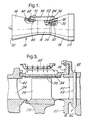
- a gas turbine engine turbomachine 10 is shown in Figure 1 and comprises in flow series an intake 12, a compressor section 14, a combustion section 16, a turbine section 18 and an exhaust nozzle 20.
- the compressor section 14 is arranged to be driven by the turbine section 18 and the compressor section 14 may comprise one or more compressor rotors (not shown) driven by one or more turbine rotors 26 via shafts (not shown).
- the gas turbine engine 10 operates quite conventionally in that air is compressed as it flows through the compressor section 14 to the combustion section 16.
- Fuel is injected into a combustion chamber 22 in the combustion section 16 and is burnt in the air supplied by the compressor section 14 to produce hot gases.
- the hot gases flow out of the combustion section 16 through the turbine section 18 and exhaust nozzle 20 to atmosphere.
- the hot exhaust gases drive the turbine section 18 which in turn drives the compressor section 14.
- the turbine section 18 includes a stage of high pressure nozzle guide vanes 24 between which the hot exhaust gases from combustion chamber 22 flow to the turbine section.
- a high pressure turbine motor 26 is located downstream of the high pressure nozzle guide vanes 24, and the high pressure turbine rotor 26 carries a plurality of circumferentially arranged, radially extending turbine blades 28. Downstream of the turbine blades 28 is located a stage of low pressure nozzle guide vanes 30, arranged circumferentially around and extending radially from a low pressure stator disc 32.
- a shroud 34 is arranged around and spaced from the tips of the high pressure turbine blades 28 by a clearance 36.
- the downstream end 38 of shroud 34 is cantilevered from the low pressure nozzle guide vanes 30 while its upstream end 40 of the shroud 34 is located between two radial stops, radial inner stop 42 and radial outer stop 44 on the high pressure nozzle guide vanes 24.
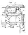
- a casing 46 encircles the nozzle guide vanes 24 and 34 and the shroud 34, and together with a member 48 defines an annular chamber 50 which receives cooling air via supply apertures 52.
- the member 48 located immediately surrounding the shroud 34, is provided with a plurality of holes 54 to allow air within the chamber 50 to be expelled in the direction of the shroud 34 to provide impingement cooling of the shroud 34. Used impingement cooling air flows through further apertures 56 in the shroud 34 into the gas stream flowing through the turbine section 18.
- the low pressure nozzle guide vanes 30 are provided with one or more passages 58 which extend radially through the low pressure nozzle guide vanes 30. These passages interconnect a chamber 60 defined between the casing 46 and the low pressure nozzle guide vanes 30 with a chamber 62 defined between the stator disc 32 and the low pressure nozzle guide vanes 30.
- the chamber 60 is connected to a bleed device 63 on the compressor section 14 of the gas turbine engine 10.
- the bleed device 63 comprises a plurality of apertures 64 in the casing 66 of the compressor section 14 thereby allowing air at a suitable pressure and temperature to be bled from the compressor section 14. This air is supplied to the chamber 60 via a pipe 68 and a valve 70.
- the passages 58 in the low pressure nozzle guide vanes 30 are preferably arranged to discharge the cooling air from the compressor section 14 such that it impinges directly upon the stator disc 32 for maximum cooling effect, ie at 90° to the stator disc surface.
- the cooling air from the passages 58 may be directed to flow along the surface of the stator disc 32 in a radially inward direction.
- the valve 70 is a two-position on/off valve and preferably is operated by the engine or an aircraft control system. For example the rate of change of throttle, fuel flow, or other aircraft control demand is monitored and used to change the state of the valve 70. Alternatively the pilot could switch the position of the valve 70.
- the valve 70 is opened to allow cooling air to be bled from the compressor section 14 through the pipe 68 to the chamber 60.
- the cooling air then flows from chamber 60 through the passages 58 in the low pressure nozzle guide vanes 30 into the chamber 62.
- Cooling air discharged from the passages 58 is directed against, or over, the stator disc 32, cooling it and reducing its diameter, which in turn causes the low pressure nozzle guide vanes 30 to be moved radially inwardly.
- This radial inward movement of the low pressure nozzle guide vanes 30 causes the shroud 34 to move radially inwards thereby reducing the clearance 36 between the shroud 34 and the rotor blade 28 tips.
- the valve 70 is operated for example during cruise conditions of an aircraft when the speed of rotation of the engine remains relatively constant.
- the valve 70 is closed to prevent cooling air flowing from the compressor section 14 to cool the stator disc 32.
- the hotter stator disc 32 increases in diameter with corresponding radial outward movements of the low pressure nozzle guide vanes 30 and shroud 34 to increase the clearance 36 between the shroud 34 and the rotor blade 28 tips.
- the valve 70 is closed for example during transient conditions and violent manoeuvring of the aircraft.
- the shroud 34 is cantilevered from its upstream 40 on the high pressure nozzle guide vanes 24 giving most movement at the trailing edge of the turbine blade 28.
- the shroud may be cantilevered from the low pressure nozzle guide vanes or high pressure nozzle guide vanes by suspending the shroud from the mid section of a lever pivoted on the high pressure nozzle guide vanes or low pressure nozzle guide vanes. This would ensure that the clearance changed uniformly at all points between the shroud and rotor blades.
Landscapes
- Engineering & Computer Science (AREA)
- Mechanical Engineering (AREA)
- General Engineering & Computer Science (AREA)
- Turbine Rotor Nozzle Sealing (AREA)
Claims (7)
- Turbomaschine mit einem Rotor, der eine Vielzahl radial nach außen ragender Rotorschaufeln (28) aufweist, weiter mit einer Statorbaugruppe auf einer Seite des Rotors, die eine Statorscheibe (32) und eine Vielzahl von Statorschaufeln (30) aufweist, die in einer ersten Stufe radial auswärts von der Statorscheibe (32) verlaufend angeordnet sind, ferner mit Wandmitteln (34), welche die Rotorschaufeln (28) mit radialem Spielraum (A, B) umgeben, wobei eine entgegengesetzte Seite der Bandmittel (34) zwischen einem inneren und einem äußeren Radialanschlag an einer benachbarten Statorbaugruppe gelegen ist, um die Radialbewegung der Wandmittel (34) zu begrenzen, und mit Strömungsmittelzuführmitteln (60, 68) die durch Ventilmittel (70) gesteuert werden und mindestens einen Kanal (58) aufweisen, der radial durch die Statorbaugruppe verläuft, dadurch gekennzeichnet, dass die Wandmittel (34) an einer Seite von der ersten Stufe der Statorschaufeln (30) auskragend angeordnet ist und der mindestens eine Kanal (58) so angeordnet ist, dass er eine Strömungsmittelzufuhr direkt auf die Statorscheibe (32) auftreffend richtet, und dass die Ventilmittel (70) zur Steuerung der Strömungsmittelzufuhr auf die Scheibe (32) zum Beeinflussen der Temperatur und daher des Durchmessers der Scheibe (32) und dadurch zur Steuerung des radialen Spielraums (A, B) zwischen den Spitzen der Rotorschaufeln (28) und den Wandmitteln (34) betätigt werden.
- Turbomaschine nach Anspruch 1, wobei die Statorscheibe (32) und die erste Stufe von Statorschaufeln (30) stromab der Rotorschaufeln (28) angeordnet sind.
- Turbomaschine nach einem der vorhergehenden Ansprüche, wobei die Ventilmittel (70) ein Ein/Aus-Ventil aufweisen, da so angeordnet ist, dass es Kühl- oder Heizmedium in einer ersten Betriebsart zufuhrt und die Zufuhr des Kühl- oder Heizmediums in einer zweiten Betriebsart beendigt.
- Turbomaschine nach einem der vorhergehenden Ansprüche, wobei die Zufuhr von Kühl- oder Heizmedium eine Zufuhr von Kühlmedium zum Kühlen der Statorscheibe (32) ist, wobei die Ventilmittel (70) so ausgelegt sind, dass sie Kühlmedium zur Statorscheibe (32) zum Kühlen der Statorscheibe zur Verringerung des Spielraums zwischen der Wand (34) und den Rotorschaufeln (28) während des Normallauf zuführen und die Zufuhr von Kühlmedium zur Statorscheibe (32) zur Vergrößerung des Spielraums zwischen der Wand und den Rotorschaufeln (28) während des Hochdrehzahlbetriebs der Turbomaschine beendigen.
- Turbomaschine nach einem der vorhergehenden Ansprüche, wobei die Turbomaschine ein Gasturbinentriebwerk ist.
- Turbomaschine nach Anspruch 5, wobei der Rotor ein Turbinenrotor und der Stator ein Turbinenstator ist
- Turbomaschine nach Anspruch 6, wobei die Mittel zur Zufuhr von Kühl- oder Heizmedium Abzweigmittel zum Abzweigen von Medium vom Verdichter des Gasturbinentriebwerks umfassen.
Applications Claiming Priority (2)
| Application Number | Priority Date | Filing Date | Title |
|---|---|---|---|
| GB9602842A GB2310255B (en) | 1996-02-13 | 1996-02-13 | A turbomachine |
| GB9602842 | 1996-02-13 |
Publications (3)
| Publication Number | Publication Date |
|---|---|
| EP0790390A2 EP0790390A2 (de) | 1997-08-20 |
| EP0790390A3 EP0790390A3 (de) | 1999-05-12 |
| EP0790390B1 true EP0790390B1 (de) | 2003-03-12 |
Family
ID=10788556
Family Applications (1)
| Application Number | Title | Priority Date | Filing Date |
|---|---|---|---|
| EP97300344A Expired - Lifetime EP0790390B1 (de) | 1996-02-13 | 1997-01-20 | Rotorschaufelspitzenabdichtung einer Turbomaschine |
Country Status (4)
| Country | Link |
|---|---|
| US (1) | US5772400A (de) |
| EP (1) | EP0790390B1 (de) |
| DE (1) | DE69719579T2 (de) |
| GB (1) | GB2310255B (de) |
Families Citing this family (39)
| Publication number | Priority date | Publication date | Assignee | Title |
|---|---|---|---|---|
| DE19839592A1 (de) * | 1998-08-31 | 2000-03-02 | Asea Brown Boveri | Strömungsmaschine mit gekühlter Rotorwelle |
| US6120242A (en) * | 1998-11-13 | 2000-09-19 | General Electric Company | Blade containing turbine shroud |
| US6393825B1 (en) * | 2000-01-25 | 2002-05-28 | General Electric Company | System for pressure modulation of turbine sidewall cavities |
| US6691519B2 (en) | 2000-02-18 | 2004-02-17 | Siemens Westinghouse Power Corporation | Adaptable modular gas turbine power plant |
| US6341938B1 (en) * | 2000-03-10 | 2002-01-29 | General Electric Company | Methods and apparatus for minimizing thermal gradients within turbine shrouds |
| GB2395756B (en) * | 2002-11-27 | 2006-02-08 | Rolls Royce Plc | Cooled turbine assembly |
| US6892931B2 (en) * | 2002-12-27 | 2005-05-17 | General Electric Company | Methods for replacing portions of turbine shroud supports |
| US7094029B2 (en) * | 2003-05-06 | 2006-08-22 | General Electric Company | Methods and apparatus for controlling gas turbine engine rotor tip clearances |
| US20050109016A1 (en) * | 2003-11-21 | 2005-05-26 | Richard Ullyott | Turbine tip clearance control system |
| DE102005013796A1 (de) * | 2005-03-24 | 2006-09-28 | Alstom Technology Ltd. | Wärmestausegment |
| DE102005013797A1 (de) * | 2005-03-24 | 2006-09-28 | Alstom Technology Ltd. | Wärmestausegment |
| US20070249823A1 (en) * | 2006-04-20 | 2007-10-25 | Chemagis Ltd. | Process for preparing gemcitabine and associated intermediates |
| US20080025838A1 (en) * | 2006-07-25 | 2008-01-31 | Siemens Power Generation, Inc. | Ring seal for a turbine engine |
| FR2907841B1 (fr) * | 2006-10-30 | 2011-04-15 | Snecma | Secteur d'anneau de turbine de turbomachine |
| US7597533B1 (en) | 2007-01-26 | 2009-10-06 | Florida Turbine Technologies, Inc. | BOAS with multi-metering diffusion cooling |
| US7665962B1 (en) | 2007-01-26 | 2010-02-23 | Florida Turbine Technologies, Inc. | Segmented ring for an industrial gas turbine |
| FR2913051B1 (fr) * | 2007-02-28 | 2011-06-10 | Snecma | Etage de turbine dans une turbomachine |
| US8038388B2 (en) | 2007-03-05 | 2011-10-18 | United Technologies Corporation | Abradable component for a gas turbine engine |
| US8616827B2 (en) * | 2008-02-20 | 2013-12-31 | Rolls-Royce Corporation | Turbine blade tip clearance system |
| US8256228B2 (en) * | 2008-04-29 | 2012-09-04 | Rolls Royce Corporation | Turbine blade tip clearance apparatus and method |
| FR2931872B1 (fr) * | 2008-05-28 | 2010-08-20 | Snecma | Turbine haute pression d'une turbomachine avec montage ameliore du boitier de pilotage des jeux radiaux d'aubes mobiles. |
| US8296037B2 (en) | 2008-06-20 | 2012-10-23 | General Electric Company | Method, system, and apparatus for reducing a turbine clearance |
| US8668459B2 (en) * | 2010-05-28 | 2014-03-11 | Hamilton Sundstrand Corporation | Turbine blade walking prevention |
| US20110293407A1 (en) * | 2010-06-01 | 2011-12-01 | Wagner Joel H | Seal and airfoil tip clearance control |
| US8944756B2 (en) | 2011-07-15 | 2015-02-03 | United Technologies Corporation | Blade outer air seal assembly |
| US9080458B2 (en) | 2011-08-23 | 2015-07-14 | United Technologies Corporation | Blade outer air seal with multi impingement plate assembly |
| EP2574732A2 (de) * | 2011-09-29 | 2013-04-03 | Hitachi Ltd. | Gasturbine |
| EP2959117B1 (de) | 2013-02-23 | 2019-07-03 | Rolls-Royce North American Technologies, Inc. | Schaufelspielraumsteuerung für einen gasturbinenmotor |
| US9453429B2 (en) * | 2013-03-11 | 2016-09-27 | General Electric Company | Flow sleeve for thermal control of a double-wall turbine shell and related method |
| US10100737B2 (en) * | 2013-05-16 | 2018-10-16 | Siemens Energy, Inc. | Impingement cooling arrangement having a snap-in plate |
| EP2826962B1 (de) * | 2013-07-15 | 2016-06-22 | MTU Aero Engines GmbH | Strömungsmaschine mit Dichtsegmenten und Leitschaufelsegmenten |
| US20160047549A1 (en) * | 2014-08-15 | 2016-02-18 | Rolls-Royce Corporation | Ceramic matrix composite components with inserts |
| US9784116B2 (en) * | 2015-01-15 | 2017-10-10 | General Electric Company | Turbine shroud assembly |
| US10443451B2 (en) | 2016-07-18 | 2019-10-15 | Pratt & Whitney Canada Corp. | Shroud housing supported by vane segments |
| US10739002B2 (en) | 2016-12-19 | 2020-08-11 | General Electric Company | Fluidic nozzle assembly for a turbine engine |
| US10612466B2 (en) * | 2017-09-11 | 2020-04-07 | United Technologies Corporation | Gas turbine engine active clearance control system using inlet particle separator |
| KR102051988B1 (ko) * | 2018-03-28 | 2019-12-04 | 두산중공업 주식회사 | 이중관 라이너 내부 유동가이드를 포함하는 가스 터빈 엔진의 연소기, 및 이를 포함하는 가스터빈 |
| US11047258B2 (en) | 2018-10-18 | 2021-06-29 | Rolls-Royce Plc | Turbine assembly with ceramic matrix composite vane components and cooling features |
| US11015475B2 (en) | 2018-12-27 | 2021-05-25 | Rolls-Royce Corporation | Passive blade tip clearance control system for gas turbine engine |
Family Cites Families (10)
| Publication number | Priority date | Publication date | Assignee | Title |
|---|---|---|---|---|
| FR1548541A (de) * | 1967-10-24 | 1968-12-06 | ||
| FR2280791A1 (fr) * | 1974-07-31 | 1976-02-27 | Snecma | Perfectionnements au reglage du jeu entre les aubes et le stator d'une turbine |
| US4117669A (en) * | 1977-03-04 | 1978-10-03 | The United States Of America As Represented By The Administrator Of The National Aeronautics And Space Administration | Apparatus and method for reducing thermal stress in a turbine rotor |
| US4157232A (en) * | 1977-10-31 | 1979-06-05 | General Electric Company | Turbine shroud support |
| FR2614073B1 (fr) * | 1987-04-15 | 1992-02-14 | Snecma | Dispositif d'ajustement en temps reel du jeu radial entre un rotor et un stator de turbomachine |
| GB2226365B (en) * | 1988-12-22 | 1993-03-10 | Rolls Royce Plc | Turbomachine clearance control |
| US5212940A (en) * | 1991-04-16 | 1993-05-25 | General Electric Company | Tip clearance control apparatus and method |
| US5169287A (en) * | 1991-05-20 | 1992-12-08 | General Electric Company | Shroud cooling assembly for gas turbine engine |
| GB9210642D0 (en) * | 1992-05-19 | 1992-07-08 | Rolls Royce Plc | Rotor shroud assembly |
| DE4411616C2 (de) * | 1994-04-02 | 2003-04-17 | Alstom | Verfahren zum Betreiben einer Strömungsmaschine |
-
1996
- 1996-02-13 GB GB9602842A patent/GB2310255B/en not_active Expired - Fee Related
-
1997
- 1997-01-20 EP EP97300344A patent/EP0790390B1/de not_active Expired - Lifetime
- 1997-01-20 DE DE69719579T patent/DE69719579T2/de not_active Expired - Lifetime
- 1997-01-27 US US08/791,487 patent/US5772400A/en not_active Expired - Lifetime
Also Published As
| Publication number | Publication date |
|---|---|
| EP0790390A3 (de) | 1999-05-12 |
| US5772400A (en) | 1998-06-30 |
| DE69719579D1 (de) | 2003-04-17 |
| DE69719579T2 (de) | 2003-12-11 |
| GB9602842D0 (en) | 1996-04-10 |
| GB2310255A (en) | 1997-08-20 |
| GB2310255B (en) | 1999-06-16 |
| EP0790390A2 (de) | 1997-08-20 |
Similar Documents
| Publication | Publication Date | Title |
|---|---|---|
| EP0790390B1 (de) | Rotorschaufelspitzenabdichtung einer Turbomaschine | |
| EP1252424B1 (de) | Verfahren zum betrieb einer gasturbine mit verstellbaren leitschaufeln | |
| US6585482B1 (en) | Methods and apparatus for delivering cooling air within gas turbines | |
| US10578028B2 (en) | Compressor bleed auxiliary turbine | |
| US4329114A (en) | Active clearance control system for a turbomachine | |
| CA2519823C (en) | Methods and apparatus for assembling a gas turbine engine | |
| JP5514354B2 (ja) | 流量調節ファンを備えたタービンエンジンとその動作方法 | |
| US10711702B2 (en) | Mixed flow turbocore | |
| CN107120146B (zh) | 主动hpc间隙控制 | |
| US7269955B2 (en) | Methods and apparatus for maintaining rotor assembly tip clearances | |
| EP2375005B1 (de) | Verfahren zur steuerung des schaufelspitzendichtspalts einer turbine | |
| US10113486B2 (en) | Method and system for modulated turbine cooling | |
| EP3133246A1 (de) | Luftstromeinspritzdüse für einen gasturbinenmotor | |
| EP1013937A2 (de) | Abzapfringraum bei den Schaufelspitzen eines Gasturbinentriebwerks | |
| US7353647B2 (en) | Methods and apparatus for assembling gas turbine engines | |
| CN110017211A (zh) | 具有密封件的涡轮发动机 | |
| CN116464561B (zh) | 在发动机停机期间旋转压缩机的加压气流 | |
| EP3351767B1 (de) | Zwischengekühltes kühlluftsystem mit bypass |
Legal Events
| Date | Code | Title | Description |
|---|---|---|---|
| PUAI | Public reference made under article 153(3) epc to a published international application that has entered the european phase |
Free format text: ORIGINAL CODE: 0009012 |
|
| AK | Designated contracting states |
Kind code of ref document: A2 Designated state(s): DE FR |
|
| 17P | Request for examination filed |
Effective date: 19980212 |
|
| PUAL | Search report despatched |
Free format text: ORIGINAL CODE: 0009013 |
|
| AK | Designated contracting states |
Kind code of ref document: A3 Designated state(s): DE FR |
|
| 17Q | First examination report despatched |
Effective date: 20010628 |
|
| GRAH | Despatch of communication of intention to grant a patent |
Free format text: ORIGINAL CODE: EPIDOS IGRA |
|
| GRAH | Despatch of communication of intention to grant a patent |
Free format text: ORIGINAL CODE: EPIDOS IGRA |
|
| GRAA | (expected) grant |
Free format text: ORIGINAL CODE: 0009210 |
|
| AK | Designated contracting states |
Designated state(s): DE FR |
|
| REF | Corresponds to: |
Ref document number: 69719579 Country of ref document: DE Date of ref document: 20030417 Kind code of ref document: P |
|
| ET | Fr: translation filed | ||
| PLBE | No opposition filed within time limit |
Free format text: ORIGINAL CODE: 0009261 |
|
| STAA | Information on the status of an ep patent application or granted ep patent |
Free format text: STATUS: NO OPPOSITION FILED WITHIN TIME LIMIT |
|
| 26N | No opposition filed |
Effective date: 20031215 |
|
| REG | Reference to a national code |
Ref country code: FR Ref legal event code: PLFP Year of fee payment: 20 |
|
| PGFP | Annual fee paid to national office [announced via postgrant information from national office to epo] |
Ref country code: DE Payment date: 20160127 Year of fee payment: 20 |
|
| PGFP | Annual fee paid to national office [announced via postgrant information from national office to epo] |
Ref country code: FR Payment date: 20160126 Year of fee payment: 20 |
|
| REG | Reference to a national code |
Ref country code: DE Ref legal event code: R071 Ref document number: 69719579 Country of ref document: DE |
|
| REG | Reference to a national code |
Ref country code: FR Ref legal event code: CA Effective date: 20170517 |