EP0790390A2 - Rotorschaufelspitzenabdichtung einer Turbomaschine - Google Patents
Rotorschaufelspitzenabdichtung einer Turbomaschine Download PDFInfo
- Publication number
- EP0790390A2 EP0790390A2 EP97300344A EP97300344A EP0790390A2 EP 0790390 A2 EP0790390 A2 EP 0790390A2 EP 97300344 A EP97300344 A EP 97300344A EP 97300344 A EP97300344 A EP 97300344A EP 0790390 A2 EP0790390 A2 EP 0790390A2
- Authority
- EP
- European Patent Office
- Prior art keywords
- shroud
- stator
- turbomachine
- cooling
- supply
- Prior art date
- Legal status (The legal status is an assumption and is not a legal conclusion. Google has not performed a legal analysis and makes no representation as to the accuracy of the status listed.)
- Granted
Links
Images
Classifications
-
- F—MECHANICAL ENGINEERING; LIGHTING; HEATING; WEAPONS; BLASTING
- F01—MACHINES OR ENGINES IN GENERAL; ENGINE PLANTS IN GENERAL; STEAM ENGINES
- F01D—NON-POSITIVE DISPLACEMENT MACHINES OR ENGINES, e.g. STEAM TURBINES
- F01D11/00—Preventing or minimising internal leakage of working-fluid, e.g. between stages
- F01D11/08—Preventing or minimising internal leakage of working-fluid, e.g. between stages for sealing space between rotor blade tips and stator
- F01D11/14—Adjusting or regulating tip-clearance, i.e. distance between rotor-blade tips and stator casing
- F01D11/20—Actively adjusting tip-clearance
- F01D11/24—Actively adjusting tip-clearance by selectively cooling-heating stator or rotor components
-
- F—MECHANICAL ENGINEERING; LIGHTING; HEATING; WEAPONS; BLASTING
- F05—INDEXING SCHEMES RELATING TO ENGINES OR PUMPS IN VARIOUS SUBCLASSES OF CLASSES F01-F04
- F05D—INDEXING SCHEME FOR ASPECTS RELATING TO NON-POSITIVE-DISPLACEMENT MACHINES OR ENGINES, GAS-TURBINES OR JET-PROPULSION PLANTS
- F05D2260/00—Function
- F05D2260/20—Heat transfer, e.g. cooling
- F05D2260/201—Heat transfer, e.g. cooling by impingement of a fluid
-
- Y—GENERAL TAGGING OF NEW TECHNOLOGICAL DEVELOPMENTS; GENERAL TAGGING OF CROSS-SECTIONAL TECHNOLOGIES SPANNING OVER SEVERAL SECTIONS OF THE IPC; TECHNICAL SUBJECTS COVERED BY FORMER USPC CROSS-REFERENCE ART COLLECTIONS [XRACs] AND DIGESTS
- Y02—TECHNOLOGIES OR APPLICATIONS FOR MITIGATION OR ADAPTATION AGAINST CLIMATE CHANGE
- Y02T—CLIMATE CHANGE MITIGATION TECHNOLOGIES RELATED TO TRANSPORTATION
- Y02T50/00—Aeronautics or air transport
- Y02T50/60—Efficient propulsion technologies, e.g. for aircraft
Definitions
- the present invention relates to turbomachines, particularly to gas turbine engines, more particularly to apparatus for controlling the clearance between rotor blades and a surrounding shroud of gas turbine engine compressors or rotors.
- the present invention seeks to provide a turbomachine with novel apparatus for controlling the clearance between the rotor blades and a surrounding shroud.
- the present invention provides a turbomachine comprising a rotor having a plurality of radially extending rotor blades, a stator including a shroud, a stator disc and a plurality of stator vanes arranged in a first stage, the first stage of stator vanes extending radially from the stator disc, the shroud being arranged around and spaced radially from the rotor blades by a clearance, the shroud being supported from the first stage of stator vanes, means to supply a cooling or heating fluid onto the stator disc and valve means to control the supply of the cooling or heating fluid onto the stator disc to control the clearance between rotor blades and the shroud.
- stator disc and the first stage of stator vanes are located downstream of the rotor blades.
- a first end of the shroud is cantilevered from the first stage of stator vanes.
- a second end of the shroud is located between inner and outer radial stops to limit movement of the shroud.
- the stops are arranged on an adjacent stage of stator vanes.
- a first end of the shroud may be cantilevered from an adjacent stage of stator vanes.
- the means to supply cooling or heating fluid comprises at least one passage extending radially through the first stage of stator vanes.
- the means to supply cooling or heating fluid is arranged to impinge the cooling or heating fluid onto the stator disc.
- valve means comprises an on/off valve arranged to supply cooling or heating fluid in a first mode of operation and to terminate the supply of cooling or heating fluid in a second mode of operation.
- the supply of cooling or heating fluid is a supply of cool fluid to cool the stator disc
- the valve means is arranged to supply cool fluid to the stator disc to cool the stator disc to reduce the clearance between the shroud and the rotor blades during cruise and the valve means is arranged to terminate the supply of cooling fluid to the stator disc to increase the clearance between the shroud and the rotor blades during high speed operation of the turbomachine.
- turbomachine is a gas turbine engine.
- the rotor may be a turbine motor and the stator may be a turbine stator.
- the means to supply cooling or heating fluid may include bleed means to bleed fluid from the compressor of the gas turbine engine.
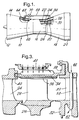
- a gas turbine engine turbomachine 10 is shown in Figure 1 and comprises in flow series an intake 12, a compressor section 14, a combustion section 16, a turbine section 18 and an exhaust nozzle 20.
- the compressor section 14 is arranged to be driven by the turbine section 18 and the compressor section 14 may comprise one or more compressor rotors (not shown) driven by one or more turbine rotors 26 via shafts (not shown).
- the gas turbine engine 10 operates quite conventionally in that air is compressed as it flows through the compressor section 14 to the combustion section 16.
- Fuel is injected into a combustion chamber 22 in the combustion section 16 and is burnt in the air supplied by the compressor section 14 to produce hot gases.
- the hot gases flow out of the combustion section 16 through the turbine section 18 and exhaust nozzle 20 to atmosphere.
- the hot exhaust gases drive the turbine section 18 which in turn drives the compressor section 14.
- the turbine section 18 includes a stage of high pressure nozzle guide vanes 24 between which the hot exhaust gases from combustion chamber 22 flow to the turbine section.
- a high pressure turbine motor 26 is located downstream of the high pressure nozzle guide vanes 24, and the high pressure turbine rotor 26 carries a plurality of circumferentially arranged, radially extending turbine blades 28. Downstream of the turbine blades 28 is located a stage of low pressure nozzle guide vanes 30, arranged circumferentially around and extending radially from a low pressure stator disc 32.
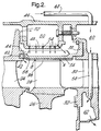
- a shroud 34 is arranged around and spaced from the tips of the high pressure turbine blades 28 by a clearance 36.
- the downstream end 38 of shroud 34 is cantilevered from the low pressure nozzle guide vanes 30 while its upstream end 40 of the shroud 34 is located between two radial stops, radial inner stop 42 and radial outer stop 44 on the high pressure nozzle guide vanes 24.
- a casing 46 encircles the nozzle guide vanes 24 and 34 and the shroud 34, and together with a member 48 defines an annular chamber 50 which receives cooling air via supply apertures 52.
- the member 48 located immediately surrounding the shroud 34, is provided with a plurality of holes 54 to allow air within the chamber 50 to be expelled in the direction of the shroud 34 to provide impingement cooling of the shroud 34. Used impingement cooling air flows through further apertures 56 in the shroud 34 into the gas stream flowing through the turbine section 18.
- the low pressure nozzle guide vanes 30 are provided with one or more passages 58 which extend radially through the low pressure nozzle guide vanes 30. These passages interconnect a chamber 60 defined between the casing 46 and the low pressure nozzle guide vanes 30 with a chamber 62 defined between the stator disc 32 and the low pressure nozzle guide vanes 30.
- the chamber 60 is connected to a bleed device 62 on the compressor section 14 of the gas turbine engine 10.
- the bleed device 62 comprises a plurality of apertures 64 in the casing 66 of the compressor section 14 thereby allowing air at a suitable pressure and temperature to be bled from the compressor section 14. This air is supplied to the chamber 60 via a pipe 68 and a valve 70.
- the passages 58 in the low pressure nozzle guide vanes 30 are preferably arranged to discharge the cooling air from the compressor section 14 such that it impinges directly upon the stator disc 32 for maximum cooling effect, ie at 90° to the stator disc surface.
- the cooling air from the passages 58 may be directed to flow along the surface of the stator disc 32 in a radially inward direction.
- the valve 70 is a two-position on/off valve and preferably is operated by the engine or an aircraft control system. For example the rate of change of throttle, fuel flow, or other aircraft control demand is monitored and used to change the state of the valve 70. Alternatively the pilot could switch the position of the valve 70.
- the valve 70 is opened to allow cooling air to be bled from the compressor section 14 through the pipe 68 to the chamber 60.
- the cooling air then flows from chamber 60 through the passages 58 in the low pressure nozzle guide vanes 30 into the chamber 62.
- Cooling air discharged from the passages 58 is directed against, or over, the stator disc 32, cooling it and reducing its diameter, which in turn causes the low pressure nozzle guide vanes 30 to be moved radially inwardly.
- This radial inward movement of the low pressure nozzle guide vanes 30 causes the shroud 34 to move radially inwards thereby reducing the clearance 36 between the shroud 34 and the rotor blade 28 tips.
- the valve 70 is operated for example during cruise conditions of an aircraft when the speed of rotation of the engine remains relatively constant.
- the valve 70 is closed to prevent cooling air flowing from the compressor section 14 to cool the stator disc 32.
- the hotter stator disc 32 increases in diameter with corresponding radial outward movements of the low pressure nozzle guide vanes 30 and shroud 34 to increase the clearance 36 between the shroud 34 and the rotor blade 28 tips.
- the valve 70 is closed for example during transient conditions and violent manoeuvring of the aircraft.
- the shroud 34 is cantilevered from its upstream 40 on the high pressure nozzle guide vanes 24 giving most movement at the trailing edge of the turbine blade 28.
- the shroud may be cantilevered from the low pressure nozzle guide vanes or high pressure nozzle guide vanes by suspending the shroud from the mid section of a lever pivoted on the high pressure nozzle guide vanes or low pressure nozzle guide vanes. This would ensure that the clearance changed uniformly at all points between the shroud and rotor blades.
Landscapes
- Engineering & Computer Science (AREA)
- Mechanical Engineering (AREA)
- General Engineering & Computer Science (AREA)
- Turbine Rotor Nozzle Sealing (AREA)
Applications Claiming Priority (2)
| Application Number | Priority Date | Filing Date | Title |
|---|---|---|---|
| GB9602842A GB2310255B (en) | 1996-02-13 | 1996-02-13 | A turbomachine |
| GB9602842 | 1996-02-13 |
Publications (3)
| Publication Number | Publication Date |
|---|---|
| EP0790390A2 true EP0790390A2 (de) | 1997-08-20 |
| EP0790390A3 EP0790390A3 (de) | 1999-05-12 |
| EP0790390B1 EP0790390B1 (de) | 2003-03-12 |
Family
ID=10788556
Family Applications (1)
| Application Number | Title | Priority Date | Filing Date |
|---|---|---|---|
| EP97300344A Expired - Lifetime EP0790390B1 (de) | 1996-02-13 | 1997-01-20 | Rotorschaufelspitzenabdichtung einer Turbomaschine |
Country Status (4)
| Country | Link |
|---|---|
| US (1) | US5772400A (de) |
| EP (1) | EP0790390B1 (de) |
| DE (1) | DE69719579T2 (de) |
| GB (1) | GB2310255B (de) |
Cited By (3)
| Publication number | Priority date | Publication date | Assignee | Title |
|---|---|---|---|---|
| EP0984138A2 (de) * | 1998-08-31 | 2000-03-08 | Asea Brown Boveri AG | Strömungsmaschine mit gekühlter Rotorwelle |
| EP1120559A3 (de) * | 2000-01-25 | 2004-08-25 | General Electric Company | System und Methode zur Modulation des Kühlluftdrucks in Turbinenhohlräumen |
| US8944756B2 (en) | 2011-07-15 | 2015-02-03 | United Technologies Corporation | Blade outer air seal assembly |
Families Citing this family (36)
| Publication number | Priority date | Publication date | Assignee | Title |
|---|---|---|---|---|
| US6120242A (en) * | 1998-11-13 | 2000-09-19 | General Electric Company | Blade containing turbine shroud |
| US6691519B2 (en) | 2000-02-18 | 2004-02-17 | Siemens Westinghouse Power Corporation | Adaptable modular gas turbine power plant |
| US6341938B1 (en) * | 2000-03-10 | 2002-01-29 | General Electric Company | Methods and apparatus for minimizing thermal gradients within turbine shrouds |
| GB2395756B (en) | 2002-11-27 | 2006-02-08 | Rolls Royce Plc | Cooled turbine assembly |
| US6892931B2 (en) * | 2002-12-27 | 2005-05-17 | General Electric Company | Methods for replacing portions of turbine shroud supports |
| US7094029B2 (en) * | 2003-05-06 | 2006-08-22 | General Electric Company | Methods and apparatus for controlling gas turbine engine rotor tip clearances |
| US20050109016A1 (en) * | 2003-11-21 | 2005-05-26 | Richard Ullyott | Turbine tip clearance control system |
| DE102005013796A1 (de) * | 2005-03-24 | 2006-09-28 | Alstom Technology Ltd. | Wärmestausegment |
| DE102005013797A1 (de) * | 2005-03-24 | 2006-09-28 | Alstom Technology Ltd. | Wärmestausegment |
| US20070249823A1 (en) * | 2006-04-20 | 2007-10-25 | Chemagis Ltd. | Process for preparing gemcitabine and associated intermediates |
| US20080025838A1 (en) * | 2006-07-25 | 2008-01-31 | Siemens Power Generation, Inc. | Ring seal for a turbine engine |
| FR2907841B1 (fr) * | 2006-10-30 | 2011-04-15 | Snecma | Secteur d'anneau de turbine de turbomachine |
| US7665962B1 (en) | 2007-01-26 | 2010-02-23 | Florida Turbine Technologies, Inc. | Segmented ring for an industrial gas turbine |
| US7597533B1 (en) | 2007-01-26 | 2009-10-06 | Florida Turbine Technologies, Inc. | BOAS with multi-metering diffusion cooling |
| FR2913051B1 (fr) * | 2007-02-28 | 2011-06-10 | Snecma | Etage de turbine dans une turbomachine |
| US8038388B2 (en) | 2007-03-05 | 2011-10-18 | United Technologies Corporation | Abradable component for a gas turbine engine |
| US8616827B2 (en) * | 2008-02-20 | 2013-12-31 | Rolls-Royce Corporation | Turbine blade tip clearance system |
| US8256228B2 (en) * | 2008-04-29 | 2012-09-04 | Rolls Royce Corporation | Turbine blade tip clearance apparatus and method |
| FR2931872B1 (fr) * | 2008-05-28 | 2010-08-20 | Snecma | Turbine haute pression d'une turbomachine avec montage ameliore du boitier de pilotage des jeux radiaux d'aubes mobiles. |
| US8296037B2 (en) * | 2008-06-20 | 2012-10-23 | General Electric Company | Method, system, and apparatus for reducing a turbine clearance |
| US8668459B2 (en) * | 2010-05-28 | 2014-03-11 | Hamilton Sundstrand Corporation | Turbine blade walking prevention |
| US20110293407A1 (en) * | 2010-06-01 | 2011-12-01 | Wagner Joel H | Seal and airfoil tip clearance control |
| US9080458B2 (en) | 2011-08-23 | 2015-07-14 | United Technologies Corporation | Blade outer air seal with multi impingement plate assembly |
| EP2574732A2 (de) * | 2011-09-29 | 2013-04-03 | Hitachi Ltd. | Gasturbine |
| EP2959117B1 (de) | 2013-02-23 | 2019-07-03 | Rolls-Royce North American Technologies, Inc. | Schaufelspielraumsteuerung für einen gasturbinenmotor |
| US9453429B2 (en) * | 2013-03-11 | 2016-09-27 | General Electric Company | Flow sleeve for thermal control of a double-wall turbine shell and related method |
| US10100737B2 (en) * | 2013-05-16 | 2018-10-16 | Siemens Energy, Inc. | Impingement cooling arrangement having a snap-in plate |
| EP2826962B1 (de) * | 2013-07-15 | 2016-06-22 | MTU Aero Engines GmbH | Strömungsmaschine mit Dichtsegmenten und Leitschaufelsegmenten |
| US20160047549A1 (en) * | 2014-08-15 | 2016-02-18 | Rolls-Royce Corporation | Ceramic matrix composite components with inserts |
| US9784116B2 (en) * | 2015-01-15 | 2017-10-10 | General Electric Company | Turbine shroud assembly |
| US10443451B2 (en) | 2016-07-18 | 2019-10-15 | Pratt & Whitney Canada Corp. | Shroud housing supported by vane segments |
| US10739002B2 (en) | 2016-12-19 | 2020-08-11 | General Electric Company | Fluidic nozzle assembly for a turbine engine |
| US10612466B2 (en) * | 2017-09-11 | 2020-04-07 | United Technologies Corporation | Gas turbine engine active clearance control system using inlet particle separator |
| KR102051988B1 (ko) * | 2018-03-28 | 2019-12-04 | 두산중공업 주식회사 | 이중관 라이너 내부 유동가이드를 포함하는 가스 터빈 엔진의 연소기, 및 이를 포함하는 가스터빈 |
| US11047258B2 (en) | 2018-10-18 | 2021-06-29 | Rolls-Royce Plc | Turbine assembly with ceramic matrix composite vane components and cooling features |
| US11015475B2 (en) | 2018-12-27 | 2021-05-25 | Rolls-Royce Corporation | Passive blade tip clearance control system for gas turbine engine |
Citations (4)
| Publication number | Priority date | Publication date | Assignee | Title |
|---|---|---|---|---|
| US3535873A (en) * | 1967-10-24 | 1970-10-27 | Joseph Szydlowski | Gas turbine cooling devices |
| US4117669A (en) * | 1977-03-04 | 1978-10-03 | The United States Of America As Represented By The Administrator Of The National Aeronautics And Space Administration | Apparatus and method for reducing thermal stress in a turbine rotor |
| US4849895A (en) * | 1987-04-15 | 1989-07-18 | Societe Nationale D'etude Et De Construction De Moteurs D'aviation (Snecma) | System for adjusting radial clearance between rotor and stator elements |
| DE4411616A1 (de) * | 1994-04-02 | 1995-10-05 | Abb Management Ag | Verfahren zum Betreiben einer Strömungsmaschine |
Family Cites Families (6)
| Publication number | Priority date | Publication date | Assignee | Title |
|---|---|---|---|---|
| FR2280791A1 (fr) * | 1974-07-31 | 1976-02-27 | Snecma | Perfectionnements au reglage du jeu entre les aubes et le stator d'une turbine |
| US4157232A (en) * | 1977-10-31 | 1979-06-05 | General Electric Company | Turbine shroud support |
| GB2226365B (en) * | 1988-12-22 | 1993-03-10 | Rolls Royce Plc | Turbomachine clearance control |
| US5212940A (en) * | 1991-04-16 | 1993-05-25 | General Electric Company | Tip clearance control apparatus and method |
| US5169287A (en) * | 1991-05-20 | 1992-12-08 | General Electric Company | Shroud cooling assembly for gas turbine engine |
| GB9210642D0 (en) * | 1992-05-19 | 1992-07-08 | Rolls Royce Plc | Rotor shroud assembly |
-
1996
- 1996-02-13 GB GB9602842A patent/GB2310255B/en not_active Expired - Fee Related
-
1997
- 1997-01-20 EP EP97300344A patent/EP0790390B1/de not_active Expired - Lifetime
- 1997-01-20 DE DE69719579T patent/DE69719579T2/de not_active Expired - Lifetime
- 1997-01-27 US US08/791,487 patent/US5772400A/en not_active Expired - Lifetime
Patent Citations (4)
| Publication number | Priority date | Publication date | Assignee | Title |
|---|---|---|---|---|
| US3535873A (en) * | 1967-10-24 | 1970-10-27 | Joseph Szydlowski | Gas turbine cooling devices |
| US4117669A (en) * | 1977-03-04 | 1978-10-03 | The United States Of America As Represented By The Administrator Of The National Aeronautics And Space Administration | Apparatus and method for reducing thermal stress in a turbine rotor |
| US4849895A (en) * | 1987-04-15 | 1989-07-18 | Societe Nationale D'etude Et De Construction De Moteurs D'aviation (Snecma) | System for adjusting radial clearance between rotor and stator elements |
| DE4411616A1 (de) * | 1994-04-02 | 1995-10-05 | Abb Management Ag | Verfahren zum Betreiben einer Strömungsmaschine |
Cited By (4)
| Publication number | Priority date | Publication date | Assignee | Title |
|---|---|---|---|---|
| EP0984138A2 (de) * | 1998-08-31 | 2000-03-08 | Asea Brown Boveri AG | Strömungsmaschine mit gekühlter Rotorwelle |
| EP0984138A3 (de) * | 1998-08-31 | 2002-01-23 | Alstom | Strömungsmaschine mit gekühlter Rotorwelle |
| EP1120559A3 (de) * | 2000-01-25 | 2004-08-25 | General Electric Company | System und Methode zur Modulation des Kühlluftdrucks in Turbinenhohlräumen |
| US8944756B2 (en) | 2011-07-15 | 2015-02-03 | United Technologies Corporation | Blade outer air seal assembly |
Also Published As
| Publication number | Publication date |
|---|---|
| EP0790390B1 (de) | 2003-03-12 |
| GB2310255A (en) | 1997-08-20 |
| DE69719579D1 (de) | 2003-04-17 |
| EP0790390A3 (de) | 1999-05-12 |
| DE69719579T2 (de) | 2003-12-11 |
| GB9602842D0 (en) | 1996-04-10 |
| US5772400A (en) | 1998-06-30 |
| GB2310255B (en) | 1999-06-16 |
Similar Documents
| Publication | Publication Date | Title |
|---|---|---|
| US5772400A (en) | Turbomachine | |
| EP3181829B1 (de) | Gasturbinenmotorturbinenkühlsystem | |
| CN108204250B (zh) | 用于涡轮发动机的流体喷嘴组件 | |
| EP1252424B1 (de) | Verfahren zum betrieb einer gasturbine mit verstellbaren leitschaufeln | |
| US6585482B1 (en) | Methods and apparatus for delivering cooling air within gas turbines | |
| EP1630385B1 (de) | Verfahren und Vorrichtung zur Aufrechterhaltung des Schaufelspitzenspiels einer Rotoranordnung | |
| JP5514354B2 (ja) | 流量調節ファンを備えたタービンエンジンとその動作方法 | |
| US7094029B2 (en) | Methods and apparatus for controlling gas turbine engine rotor tip clearances | |
| EP3133249A1 (de) | Gasturbine mit einem entlüftungssystem | |
| EP2333237B1 (de) | Bläser mit mehrstufigen Schaufeln an der Spitze | |
| EP2375005B1 (de) | Verfahren zur steuerung des schaufelspitzendichtspalts einer turbine | |
| EP2204533B1 (de) | Verfahren, Systeme und/oder Vorrichtungen in Bezug auf Drallvorrichtungen für Turbinenantriebe | |
| US20070209368A1 (en) | High pressure ratio aft fan | |
| EP2333238A2 (de) | Gasturbinenmotor mit Außenbläsern | |
| CN107120146B (zh) | 主动hpc间隙控制 | |
| EP1013937A2 (de) | Abzapfringraum bei den Schaufelspitzen eines Gasturbinentriebwerks | |
| EP3153661A1 (de) | Verfahren und system zur modulierten turbinenkühlung | |
| JPH0120320B2 (de) | ||
| WO2016039918A1 (en) | Axi-centrifugal compressor with variable outlet guide vanes | |
| EP0769093A1 (de) | Schauffelzusammensetzung für eine gasturbine mit integrierter kühldüse | |
| US7353647B2 (en) | Methods and apparatus for assembling gas turbine engines | |
| CN114718656B (zh) | 用于控制燃气涡轮发动机内的叶片间隙的系统 | |
| CN113123878B (zh) | 不同α的可变面积计量 | |
| CN110017211A (zh) | 具有密封件的涡轮发动机 | |
| WO2015094990A1 (en) | Adjustable clearance control system for airfoil tip in gas turbine engine |
Legal Events
| Date | Code | Title | Description |
|---|---|---|---|
| PUAI | Public reference made under article 153(3) epc to a published international application that has entered the european phase |
Free format text: ORIGINAL CODE: 0009012 |
|
| AK | Designated contracting states |
Kind code of ref document: A2 Designated state(s): DE FR |
|
| 17P | Request for examination filed |
Effective date: 19980212 |
|
| PUAL | Search report despatched |
Free format text: ORIGINAL CODE: 0009013 |
|
| AK | Designated contracting states |
Kind code of ref document: A3 Designated state(s): DE FR |
|
| 17Q | First examination report despatched |
Effective date: 20010628 |
|
| GRAH | Despatch of communication of intention to grant a patent |
Free format text: ORIGINAL CODE: EPIDOS IGRA |
|
| GRAH | Despatch of communication of intention to grant a patent |
Free format text: ORIGINAL CODE: EPIDOS IGRA |
|
| GRAA | (expected) grant |
Free format text: ORIGINAL CODE: 0009210 |
|
| AK | Designated contracting states |
Designated state(s): DE FR |
|
| REF | Corresponds to: |
Ref document number: 69719579 Country of ref document: DE Date of ref document: 20030417 Kind code of ref document: P |
|
| ET | Fr: translation filed | ||
| PLBE | No opposition filed within time limit |
Free format text: ORIGINAL CODE: 0009261 |
|
| STAA | Information on the status of an ep patent application or granted ep patent |
Free format text: STATUS: NO OPPOSITION FILED WITHIN TIME LIMIT |
|
| 26N | No opposition filed |
Effective date: 20031215 |
|
| REG | Reference to a national code |
Ref country code: FR Ref legal event code: PLFP Year of fee payment: 20 |
|
| PGFP | Annual fee paid to national office [announced via postgrant information from national office to epo] |
Ref country code: DE Payment date: 20160127 Year of fee payment: 20 |
|
| PGFP | Annual fee paid to national office [announced via postgrant information from national office to epo] |
Ref country code: FR Payment date: 20160126 Year of fee payment: 20 |
|
| REG | Reference to a national code |
Ref country code: DE Ref legal event code: R071 Ref document number: 69719579 Country of ref document: DE |
|
| REG | Reference to a national code |
Ref country code: FR Ref legal event code: CA Effective date: 20170517 |