EP0790102A1 - Compact guide rail lock implement or plier with roughly and fine stepless parallel to upper gripper jaw shifting adjustment of lower gripper jaw with unishape guide block as well as with integrated measuring arrangement - Google Patents
Compact guide rail lock implement or plier with roughly and fine stepless parallel to upper gripper jaw shifting adjustment of lower gripper jaw with unishape guide block as well as with integrated measuring arrangement Download PDFInfo
- Publication number
- EP0790102A1 EP0790102A1 EP97102207A EP97102207A EP0790102A1 EP 0790102 A1 EP0790102 A1 EP 0790102A1 EP 97102207 A EP97102207 A EP 97102207A EP 97102207 A EP97102207 A EP 97102207A EP 0790102 A1 EP0790102 A1 EP 0790102A1
- Authority
- EP
- European Patent Office
- Prior art keywords
- lower jaw
- guide
- jaw
- lever
- pliers
- Prior art date
- Legal status (The legal status is an assumption and is not a legal conclusion. Google has not performed a legal analysis and makes no representation as to the accuracy of the status listed.)
- Withdrawn
Links
Images

Classifications
-
- B—PERFORMING OPERATIONS; TRANSPORTING
- B25—HAND TOOLS; PORTABLE POWER-DRIVEN TOOLS; MANIPULATORS
- B25B—TOOLS OR BENCH DEVICES NOT OTHERWISE PROVIDED FOR, FOR FASTENING, CONNECTING, DISENGAGING OR HOLDING
- B25B7/00—Pliers; Other hand-held gripping tools with jaws on pivoted limbs; Details applicable generally to pivoted-limb hand tools
- B25B7/22—Pliers provided with auxiliary tool elements, e.g. cutting edges, nail extractors
-
- B—PERFORMING OPERATIONS; TRANSPORTING
- B25—HAND TOOLS; PORTABLE POWER-DRIVEN TOOLS; MANIPULATORS
- B25B—TOOLS OR BENCH DEVICES NOT OTHERWISE PROVIDED FOR, FOR FASTENING, CONNECTING, DISENGAGING OR HOLDING
- B25B7/00—Pliers; Other hand-held gripping tools with jaws on pivoted limbs; Details applicable generally to pivoted-limb hand tools
- B25B7/02—Jaws
- B25B7/04—Jaws adjustable
-
- B—PERFORMING OPERATIONS; TRANSPORTING
- B25—HAND TOOLS; PORTABLE POWER-DRIVEN TOOLS; MANIPULATORS
- B25B—TOOLS OR BENCH DEVICES NOT OTHERWISE PROVIDED FOR, FOR FASTENING, CONNECTING, DISENGAGING OR HOLDING
- B25B7/00—Pliers; Other hand-held gripping tools with jaws on pivoted limbs; Details applicable generally to pivoted-limb hand tools
- B25B7/06—Joints
- B25B7/10—Joints with adjustable fulcrum
-
- B—PERFORMING OPERATIONS; TRANSPORTING
- B25—HAND TOOLS; PORTABLE POWER-DRIVEN TOOLS; MANIPULATORS
- B25B—TOOLS OR BENCH DEVICES NOT OTHERWISE PROVIDED FOR, FOR FASTENING, CONNECTING, DISENGAGING OR HOLDING
- B25B7/00—Pliers; Other hand-held gripping tools with jaws on pivoted limbs; Details applicable generally to pivoted-limb hand tools
- B25B7/12—Pliers; Other hand-held gripping tools with jaws on pivoted limbs; Details applicable generally to pivoted-limb hand tools involving special transmission means between the handles and the jaws, e.g. toggle levers, gears
Definitions
- the invention relates to clamp-type, clamp-type or plier-type tools, in particular pliers for gripping, holding, clamping, pressing, squeezing, embossing, notching, punching, shearing, contouring, bending, folding, other shaping, material testing and Twisting, twisting, in particular screwing, with gripping surfaces of their jaws that are steplessly parallel to each other along their entire opening / closing path, whereby the fixed leg component with a slot milled out in the middle of the flat sides of the tool / pliers for penetration through a side guide sheet molded onto the lower jaw with guide slides formed on the lower lever and upper jaw and provided with an elongated guide and locking shaft as a guide element for the longitudinal displacement of the lower jaw with its I-guide profile-like molded parts, the guide blade is milled out in the middle between the flat sides of the tool / pliers aesthetic slot takes and where the upper lever designed as a loose leg with its inserted locking pin in the one-sided latched slot of the guide
- Both front, cheek-side webs of the guide and locking shank, delimited by milling slot, lower jaw guide edges and elongated hole, correspond to the I-guide profile-like molded parts of the lower jaw and are straight, smooth on their long sides, while both rear, delimited by milling slot, elongated hole and anti-jamming support edges
- Actuator lever, pliers leg-side webs on the tool / pliers back within the elongated hole contour with their pliers leg-side notch depressions correspond to a locking pin with its flattening directed towards the ends of the actuating lever / pliers leg.
- the detent recesses with their partial areas of their contour curved upwards towards the upper jaw give the detent pin a rotation during its rotation while pivoting the upper lever during the opening or closing process, albeit interrupted by the milling slot lying in the center of the flat sides of the tool and pliers, depending on the angle of the loose leg
- the upper lever on the above-mentioned curvature offers migratory support, the lower jaw is informed of its displacement directly by the short end of the upper lever additional displacement path, so that more than sufficient coverage - as can only be achieved with simply rounded catches - is shown by the upper lever during the fine adjustment pivoting.
- the large displacement path of the lower jaw which is achieved anyway, protrudes the shorter end of the upper lever far below the lower jaw and relieves pressure on the guide parts molded onto the lower jaw as well as the guide parts on which they slide, so that the pieces of material involved in the parallel guidance could be made relatively short and lightweight.
- the elongated hole has moved closer to the lower jaw's guideway due to smaller cross-sections of the front, jaw-side webs; Although tight, inexpensive guidance with a large distance between the slide of the lower jaw on its leading edge was achieved, this had to be accepted. that the elongated hole in its lower, into the lower lever area for receiving the locking pin was angled with a large jaw adjustment in the direction of the upper lever, but this does not mean any further increase in width due to the widening of the guide and locking shank required for the anti-jam thickening on the upper lever.
- a bracket is formed on the lower jaw for the approximately half-way encirclement of the displacement joint area of the upper jaw, against the inner edge of which the The upper lever is supported by a spring element.
- the lower jaw gripping surface maintains its parallelism to the upper jaw gripping surface during the longitudinal movement of the lower jaw along the guide and locking shank, its distance from the upper jaw gripping surface is used to determine its dimensions after detecting an object, by marking on the lower jaw with a graduation scale on the flat side of the / one of the front, Cheek-side webs similar to a slide gauge.
- Further adapter / plug-on jaws are with profile, squeeze, Bending, embossing, shaping, shearing, penetrating or other tools are equipped, which are equipped for forming and / or for the purpose of generating or changing an electronically processed signal or another, also sensory part for measuring quantity acquisition, whereby a connected processor unit further processing, for example for workpiece processing or material testing, is made possible by reading and / or documenting quantitative displays during use. It is also possible to accommodate such sensor and signal processing units directly in the lower jaw, although the area of exposure to them is relatively large due to the shorter end of the upper lever and a special mechanism must direct the force exerted by the upper lever onto the sensor.
- the functioning of the tool / pliers according to the invention is such that when the hand lever / pliers leg pivoting opens, the upper lever releases the locking pin used in it against the persistence tendency by spring pressure on the lower jaw surrounding bracket from the upper lever from one of the notches in the series of detents. Then the lower jaw is roughly adjusted by moving the upper lever relative to the lower lever either by contacting a workpiece or by selecting a work area in terms of size, along with sliding the cylindrical rounding of the locking pin on the straight, smooth web side in the slot to one of the catches of the displacement joint.
- the locking pin is screwed into the pre-selected or adjacent detent by rotating the locking pin with the upper lever swiveling; the flat side of the locking pin is rolled on the curvature of the detent directed towards the brooks and thus the entire upper lever portion of the displacement joint is raised at the same time as the lever force displacement of the lower jaw, so that an increased coverage of the lower jaw adjustment range from neighboring ones Rest out is used.
- the displacement path covered by the lower jaw can be quantified with the path of its marking along the graduation scale.
- the object of the present invention is to provide such tools / pliers which, while observing the size class-appropriate dimension, offer the greatest possible adjustment or wrench widths for parallel jaw gripping surfaces with lightness, cost minimization and various measuring options.
- German patent application file number 195 23 678.5, a parallel guide tool with an I-guide profile molded onto the lower jaw, received and guided in a milling slot parallel to the tool / pliers flat side, is known, but the sliding block-like one corresponding to the flange of the I-profile Guide carriage as a pin with a round, semicircular or elliptical / non-circular profile cross-section was pressed into the side guide sheet corresponding to the high bridge, whereby this guide pin, which was not made of the same material, in practice led to a completely unsatisfactory width across flats and, with a somewhat more heavy-weight design, to dysfunction, otherwise the lower jaw was only indirectly supported by the shorter end of the upper lever, so that due to the high load on the guide parts unsatisfactory service life, therefore less successful requirement of parallel guidance was to be feared.
- the angling of the elongated hole contour of a tool / pliers with application areas mentioned at the beginning is a novelty.
- Another novelty is the border that half-encloses the displacement joint area of the upper lever by means of the lower jaw, which can be displaced longitudinally on the guide and locking shaft, by means of its molded parts in order to maintain the connection between the upper lever and the lower jaw, with a spring element holding the shorter end of the upper lever in such a way against the lower edge of the lower jaw, that the detachment of the locking pin can only be released with the intention of the operator.
- the introduction of the locking pin, with its flattened obliquely downward toward the ends of the tool hand levers / pliers limbs is an advantageous embodiment of the present invention and a novelty compared to known tools / pliers with simpler tasks and with completion of the functions required according to the invention is to achieve the articulation displacement after releasing the locking pin from one of the detents at a smaller swivel angle with an additional displacement path for the lower jaw on its closing path, by the point of contact / the contact line of the locking pin flattening on the curvature of the detents directed towards the upper jaw, with the tool hand levers then being pivoted / the pliers leg moves in the direction of the I-flange-like guide carriage in the elongated hole area located above, and an additional lifting effect is thus communicated to the upper lever and the lower jaw acted upon by it .
- the lifting effect achieved in this way has a comparatively minor effect, but it is a welcome extension of the adjustment coverage of the individual coarse and fine adjustment widths of the lower jaw from notch to notch, so that on the one hand the shorter end of the upper lever during its power stroke on the lower jaw under engagement between the molded parts of the lower jaw and on the other hand the locking pin itself, and consequently also the overall width of the guide and locking shaft would not have to be made excessively large.
- Novel and representing an advantageous embodiment of the present invention is the attachment of a length measuring graduation scale on the guide and locking shaft, on which a marking on the lower jaw is pushed in a straight line and in the same plane in the manner of slide gauges.
Abstract
Kompaktschloßwerkzeug oder -zange mit bei Grob- und Feinverstellung stufenlos überdeckendem Parallelgriff, mit angeformtem Führungsschlitten, mit integrierten Meßeinrichtungen sowie mit auswechselbaren Aufsteckbacken, wobei der Oberhebel, ausgestattet mit eingepreßtem Raststift, der zu den Enden der Handhebel / Zangenschenkel hin gerichtete Abflachung aufweist, die mit angeformtem I-Führungsprofil-artigem Seitenführungsblatt mit materialeinheitlichem Führungsschlitten sowie mit materialeinheitlichem Verlagerungsgelenkumfassungsbügel versehene Unterbacke direkt und unmittelbar unterstützend beaufschlagt und diese dabei entlang einem aus Backen-seitigen, vorderen Führungsstegen sowie hinteren, Werkzeug- / Zangenrücken-seitigen Heberasten-Verlagerungsgelenkstegen bestehendem Führungs- und Rastenschaft mit Längenmaß-Teilstrichskala unter Erhaltung der Parallelität beider Backengreifflächen verschiebt und wobei ausgeübte Drehmomente, Scher- und sonstige Verformungskräfte mittels integrierter Sensortechnik und Datenverarbeitung in / an Oberhebel, Unterbacke und / oder Aufsteckbacken mit oder ohne angebrachtem Werkzeug erfaßt, verarbeitet, abgelesen und oder zu externer Verarbeitung weitergeleitet werden. <IMAGE>Compact lock tool or pliers with a parallel handle that overlaps with coarse and fine adjustment, with a molded guide slide, with integrated measuring devices and with interchangeable push-on jaws, whereby the upper lever, equipped with a pressed-in locking pin, has a flattened surface that faces the ends of the hand lever / pliers legs Molded-on I-guide profile-like side guide sheet with a material-specific guide slide and a lower jaw provided with a material-specific displacement joint wrap-around bracket acted directly and directly on the support and this along a guide and locking shaft consisting of jaw-side, front guide webs and rear, tool / pliers back-side lifting peg-displacement joint webs with the length graduation scale while maintaining the parallelism of both jaw gripping surfaces and while exerted torques, shear and other deformation forces by means of integrated sensor technology and data processing in / on the upper lever, lower jaw and / or plug-on jaws with or without attached tools, processed, read and or forwarded for external processing. <IMAGE>
Description
Die Erfindung betrifft Klemmen-, Zwingen- oder Zangen- artige Werkzeuge, insbesondere Zangen für Greifen, Halten, Festklemmen, Pressen, Quetschen, Prägen, Kerben, Lochen, Abscheren, Konturieren, Biegen, Abkanten, sonstige Verrichtungen der Formgebung, der Werkstoffprüfung sowie des Verdrehens, des Verdrillens, insbesondere des Verschraubens mit auf ihrem gesamten Öffnungs-/Schließweg stufenlos parallel zueinander geführten Greifflächen ihrer Backen, wobei der als Festschenkelbestandteil mit einem mittig zu den Flachseiten des Werkzeugs / der Zange ausgefrästen Schlitz zur Durchdringung durch ein an die Unterbacke angeformtes Seitenführungsblatt mit Führungsschlitten an Unterhebel und an Oberbacke angeformtes sowie mit Langloch versehene Führungs- und Rastenschaft als Führungselement für die Längsverschiebung der Unterbacke mit ihren I-Führungsprofil -artigen Anformteilen dient, das Führungsblatt in seinen mittig zwischen den Flachseiten des Werkzeugs / der Zange ausgefrästen Schlitz aufnimmt und wobei der als Losschenkel ausgeführte Oberhebel mit seinem eingesetzten Raststift im einseitig verrasteten Langloch des Führungs- und Rastenschafts eine eine Serie von Gelenkrasten findet, um mit diesen verlagerbare Gelenke zu bilden, über welche der Oberhebel mit seinem kurzen Ende die Unterbacke unmittelbar mit Verschiebekräften beaufschlagt, während die Führungskräfte für die Unterbacke vom an das Seitenführungsblatt angeformten, Kulissensteinartigen Flansch-Teil, dem Führungsschlitten des I-Führungsprofils und von den Laufkanten der Unterbacke auf die vorderen, Backen-seitigen Stege der Langlochumrandung abgesetzt werden.The invention relates to clamp-type, clamp-type or plier-type tools, in particular pliers for gripping, holding, clamping, pressing, squeezing, embossing, notching, punching, shearing, contouring, bending, folding, other shaping, material testing and Twisting, twisting, in particular screwing, with gripping surfaces of their jaws that are steplessly parallel to each other along their entire opening / closing path, whereby the fixed leg component with a slot milled out in the middle of the flat sides of the tool / pliers for penetration through a side guide sheet molded onto the lower jaw with guide slides formed on the lower lever and upper jaw and provided with an elongated guide and locking shaft as a guide element for the longitudinal displacement of the lower jaw with its I-guide profile-like molded parts, the guide blade is milled out in the middle between the flat sides of the tool / pliers aesthetic slot takes and where the upper lever designed as a loose leg with its inserted locking pin in the one-sided latched slot of the guide and locking shaft finds a series of articulated catches to form displaceable joints with which the upper lever with its short end directly supports the lower jaw Shifting forces are applied while the executives for the lower jaw are placed on the front, jaw-side webs of the elongated hole border by the sliding block-like flange part molded onto the side guide sheet, the guide carriage of the I-guide profile and by the running edges of the lower jaw.
Beide durch Frässchlitz, Unterbackenführungskanten und Langloch begrenzte vordere, Backen-seitige Stege des Führungs- und Rastenschafts entsprechen den I-Führungsprofil-artigen Anformteilen der Unterbacke und sind an ihren Langseiten geradlinig glatt ausgeführt, während beide, durch Frässchlitz, Langloch und Klemmschutzauflagekanten begrenzte hintere, Betätigungshebel-, Zangenschenkel-seitige Stege am Werkzeug- / Zangenrücken innerhalb der Langlochkontur mit ihren Zangenschenkel-seitigen Rastenvertiefungen einem Raststift mit seiner zu den Enden der Betätigungshebel / Zangenschenkel gerichteten Abflachung entsprechen.
Indem die Rastenvertiefungen mit ihren aufwärts zur Oberbacke gewölbten Teilbereichen ihrer Kontur dem Raststift während seiner Drehung unter Verschwenken des Oberhebels beim Öffnungs- oder Schließvorgang eine, wenn auch durch den mittig zu den Werkzeug-, Zangenflachseiten liegenden Frässchlitz unterbrochene, je nach Abwinklung des Losschenkel-artigen Oberhebels auf vorbenannter Wölbung wandernde Auflage bietet, wird der Unterbacke bei ihrer Verschiebung unmittelbar durch das kurze Ende des Oberhebels zusätzlicher Verschiebeweg mitgeteilt, so daß mehr als hinreichende Überdeckung - wie nurmehr bei einfach gerundeten Rasten erreichbar - bei der Feineinstellungsverschwenkung durch den Oberhebel dargestellt wird.
Bei ausgewogener Abstimmung der Hebelkräfte ohnehin erzielter großer Verschiebeweg der Unterbacke ragt das kürzere Ende des Oberhebels weit unter die Unterbacke und entlastet bei deren Beaufschlagung die an die Unterbacke angeformten Führungsteile wie auch die Führungsteile, an welchen sie entlanggleiten, so daß die an der Parallelführung beteiligten Materialstücke relativ kurz und auch leichtgewichtig ausgeführt werden konnten.Both front, cheek-side webs of the guide and locking shank, delimited by milling slot, lower jaw guide edges and elongated hole, correspond to the I-guide profile-like molded parts of the lower jaw and are straight, smooth on their long sides, while both rear, delimited by milling slot, elongated hole and anti-jamming support edges Actuator lever, pliers leg-side webs on the tool / pliers back within the elongated hole contour with their pliers leg-side notch depressions correspond to a locking pin with its flattening directed towards the ends of the actuating lever / pliers leg.
In that the detent recesses with their partial areas of their contour curved upwards towards the upper jaw give the detent pin a rotation during its rotation while pivoting the upper lever during the opening or closing process, albeit interrupted by the milling slot lying in the center of the flat sides of the tool and pliers, depending on the angle of the loose leg The upper lever on the above-mentioned curvature offers migratory support, the lower jaw is informed of its displacement directly by the short end of the upper lever additional displacement path, so that more than sufficient coverage - as can only be achieved with simply rounded catches - is shown by the upper lever during the fine adjustment pivoting.
With a balanced adjustment of the lever forces, the large displacement path of the lower jaw, which is achieved anyway, protrudes the shorter end of the upper lever far below the lower jaw and relieves pressure on the guide parts molded onto the lower jaw as well as the guide parts on which they slide, so that the pieces of material involved in the parallel guidance could be made relatively short and lightweight.
Dank geringerer Führungskraftkomponenten bei direkter Verschiebekr äftebeaufschlagung der Unterbacke ist das Langloch durch geringere Querschnitte der vorderen, Backen-seitigen Stege nahe an die Backen-seitige Führungsbahn der Unterbacke gerückt;
damit ist zwar enge, günstige Führung bei großem Führungsschlittenabstand von der Kipplinie der Unterbacke auf ihrer Führungskante erreicht worden, dafür aber mußte in Kauf genommen werden, daß das Langloch in seinem unteren, in den Unterhebel übergehenden Bereich für die Aufnahme des Raststifts bei großer Backenverstellweite in Richtung Oberhebel abgewinkelt wurde, was jedoch aufgrund der für die Auflage der Klemmschutzverdickung am Oberhebel erforderliche Verbreiterung des Führungs- und Rastenschafts keine weitere Breitenzunahme bedeutet.Thanks to lower guide force components when the lower jaw is subjected to direct sliding forces, the elongated hole has moved closer to the lower jaw's guideway due to smaller cross-sections of the front, jaw-side webs;
Although tight, inexpensive guidance with a large distance between the slide of the lower jaw on its leading edge was achieved, this had to be accepted. that the elongated hole in its lower, into the lower lever area for receiving the locking pin was angled with a large jaw adjustment in the direction of the upper lever, but this does not mean any further increase in width due to the widening of the guide and locking shank required for the anti-jam thickening on the upper lever.
Zwecks Erhaltung der Verbindung von Oberhebel und Unterbacke in beiden Unterbackenverschieberichtungen, besonders aber für den Verbleib des Raststifts in der zur jeweils gewählten Grobeinstellung gehörigen Raste ist für die erforderliche annähernd halbe Umschließung des Verlagerungsgelenkbereichs der Oberbacke ein Bügel an die Unterbacke angeformt, gegen dessen Innenrandung sich der Oberhebel mittels Federelement abstützt.In order to maintain the connection between the upper lever and the lower jaw in both lower jaw displacement directions, but especially for the retention of the locking pin in the detent belonging to the rough setting selected, a bracket is formed on the lower jaw for the approximately half-way encirclement of the displacement joint area of the upper jaw, against the inner edge of which the The upper lever is supported by a spring element.
Da die Unterbackengreiffläche während der Unterbackenlängsverschiebung entlang des Führungs- und Rastenschafts ihre Parallelität zur Oberbackengreiffläche beibehält, dient deren Abstand zur Oberbackengreiffläche nach Erfassen eines Gegenstandes zu dessen maßlicher Bestimmung, indem eine Markierung auf der Unterbacke mit einer Teilstrichskala auf der Flachseite des / eines der vorderen, Backen-seitigen Stege ähnlich wie bei einer Schieblehre verglichen wird.Since the lower jaw gripping surface maintains its parallelism to the upper jaw gripping surface during the longitudinal movement of the lower jaw along the guide and locking shank, its distance from the upper jaw gripping surface is used to determine its dimensions after detecting an object, by marking on the lower jaw with a graduation scale on the flat side of the / one of the front, Cheek-side webs similar to a slide gauge.
Aufzubringende Kräfte bei Verdrehen eines ergriffenen Gegenstandes werden über die Biegespannung im Oberhebel mittels Veränderung des elektrischen Widerstandes in einem aufgeklebten oder auf sonstige Art befestigten Dehnungsmeßstreifen mit angeschlossener Signalverarbeitung sowie mit Anzeigeeinheit und / oder angeschlossenem Drucker / Dokumentationsmöglichkeit erfaßt.Forces to be applied when rotating a gripped object are recorded via the bending stress in the upper lever by changing the electrical resistance in a bonded or otherwise attached strain gauge with connected signal processing and with display unit and / or connected printer / documentation option.
Mit Adapter- oder Aufsteckbacken werden empfindliche Oberflächen der zu bearbeitenden Gegenstände geschont, für weitere Arbeiten Profilumschließungsbacken eingesetzt, mit welchen besondere Verdreh- oder Verschraubelemente erfaßt werden.With adapter or plug-on jaws, sensitive surfaces of the objects to be machined are spared, and profile wrapping jaws are used for further work, with which special twisting or screwing elements are detected.
Weitere Adapter- / Aufsteckbacken sind mit Profil-, Quetsch-, Biege-, Präge-, Form-, Scher-, Eindring- oder sonstigen Werkzeugen ausgestattet, die zur Umformung und / oder zwecks Erzeugung oder Veränderung eines elektronisch zu verarbeitenden Signals oder einem sonstigen, auch sensorischen Teil zur Meßgrößenerfassung ausgerüstet sind, wobei eine angeschlossene Prozessoreinheit die Weiterverarbeitung, beispielsweise zur Werkstückbearbeitung oder zur Werkstoffprüfung ermöglicht, indem quantitative Anzeigen während der Anwendung schon abgelesen und / oder dokumentiert werden.
Die Unterbringung solcher Sensor- und Signalverarbeitungseinheiten ist auch direkt in der Unterbacke möglich, wobei allerdings deren Beaufschlagungsfläche durch das kürzere Ende des Oberhebels relativ groß geraten ist und ein spezieller Mechanismus die vom Oberhebel ausgeübte Kraft auf den Sensor leiten muß.Further adapter / plug-on jaws are with profile, squeeze, Bending, embossing, shaping, shearing, penetrating or other tools are equipped, which are equipped for forming and / or for the purpose of generating or changing an electronically processed signal or another, also sensory part for measuring quantity acquisition, whereby a connected processor unit further processing, for example for workpiece processing or material testing, is made possible by reading and / or documenting quantitative displays during use.
It is also possible to accommodate such sensor and signal processing units directly in the lower jaw, although the area of exposure to them is relatively large due to the shorter end of the upper lever and a special mechanism must direct the force exerted by the upper lever onto the sensor.
Die Funktionsweise des / der erfindungsgemäßen Werkzeugs / Zange stellt sich so dar, daß unter öffnender Handhebel- / Zangenschenkelverschwenkung der Oberhebel den in ihm eingesetzten Raststift gegen die Verharrtendenz durch vom Oberhebel ausgehenden Federdruck am Unterbacken-Umfassungsbügel aus einer der Rasten in der Rastenserie löst. Sodann wird die Unterbacke mittels Oberhebelverschiebung gegenüber dem Unterhebel entweder unter Anlage an ein Werkstück oder unter Auswahl eines größenmäßigen Arbeitsbereichs, einhergehend mit Gleiten der zylindrischen Rundung des Raststifts auf der geradlinig glatten Stegseite im Langloch zu einer der Rasten des Verlagerungsgelenks grob eingestellt.
Mit schließender Verschwenkung der Handhebel / Zangenschenkel zur Erfassung eines Werkstücks zwecks Bearbeitung oder diametraler Messung wird der Raststift in die vorgewählte oder auch benachbarte Raste eingedreht, indem wie vorgenannt der Raststift mit der Oberhebelverschwenkung rotiert; dabei wird die Flachseite des Raststifts auf der zu den Bachen gerichteten Wölbung der Raste abgewälzt und somit der gesamte Oberhebelanteil des Verlagerungsgelenks gleichzeitig mit der Hebelkraftverschiebung der Unterbacke angehoben, so daß eine vergrößerte Überdeckung der Unterbackenverstellweite von benachbarten Rasten aus genutzt wird.
Bei Anlage der Backen am Werkstück, bei dessen Quetschung oder sonstiger Bearbeitung kann der von der Unterbacke zurückgelegte Verschiebeweg mit dem Weg ihrer Markierung entlang der Teilstrichskala quantitativ erfaßt werden.
Weiterhin ergibt sich, daß bei Streckung des am Oberhebel angebrachten Dehnungsmeßstreifens eine Änderung dessen elektrischen Widerstands auftritt, welche zur quantitativen Erfassung des erbrachten Drehmoments elektronisch verarbeitet wird.
Ein piezoelektrisches Element wird vom kürzeren Ende des Oberhebels über einen Mechanismus beaufschlagt, welcher sich über die gesamte Fläche erstreckt, die vom Oberhebelende auf der Unterseite der Unterbacke bestrichen wird. Der dafür erforderliche Mechanismus kann einen Balken auf zwei Stützen oder sonstige Konstrukte - wie federgehaltenes Dreikantblechbeinhalten.
Aufsteckbare Backen mit schonenden Belägen, profilumschließenden oder verformungstechnisch wirkenden Werkzeugen und Werkzeugen zur Werkstoffuntersuchung sind für Ober- und Unterbacke möglichst identisch gleich und daher seitlich aufsteckbar angefertigt.The functioning of the tool / pliers according to the invention is such that when the hand lever / pliers leg pivoting opens, the upper lever releases the locking pin used in it against the persistence tendency by spring pressure on the lower jaw surrounding bracket from the upper lever from one of the notches in the series of detents. Then the lower jaw is roughly adjusted by moving the upper lever relative to the lower lever either by contacting a workpiece or by selecting a work area in terms of size, along with sliding the cylindrical rounding of the locking pin on the straight, smooth web side in the slot to one of the catches of the displacement joint.
With the swiveling of the hand lever / pliers legs for grasping a workpiece for processing or diametrical measurement, the locking pin is screwed into the pre-selected or adjacent detent by rotating the locking pin with the upper lever swiveling; the flat side of the locking pin is rolled on the curvature of the detent directed towards the brooks and thus the entire upper lever portion of the displacement joint is raised at the same time as the lever force displacement of the lower jaw, so that an increased coverage of the lower jaw adjustment range from neighboring ones Rest out is used.
When the jaws rest on the workpiece, when it is crushed or otherwise processed, the displacement path covered by the lower jaw can be quantified with the path of its marking along the graduation scale.
It also follows that when the strain gauge attached to the upper lever is stretched, there is a change in its electrical resistance, which is electronically processed to quantify the torque produced.
A piezoelectric element is acted upon by the shorter end of the upper lever via a mechanism which extends over the entire area which is covered by the upper lever end on the underside of the lower jaw. The mechanism required for this can include a beam on two supports or other constructions - such as spring-loaded triangular sheet metal.
Snap-on jaws with gentle coverings, profile-encompassing or shaping tools and tools for material analysis are as identical as possible for the top and bottom jaws and are therefore made to be plugged on from the side.
Die Aufgabe der vorliegenden Erfindung besteht darin, solche Werkzeuge / Zangen zu schaffen, welche unter Einhaltung Größenklassen-gemäßer Abmessung größtmögliche Verstell- oder Schlüsselweiten für parallel zu führende Backengreifflächen bei Leichtgewichtigkeit, Kostenminimierung und diversen Meßmöglichkeiten bieten.
Die Lösung dieser komplexen Aufgabe ist vor allem durch Beachtung vorhandener Fertigungstechnologie gelungen, indem für Unterbackenlängsverschiebung eine I-artige Profilführung an die Unterbacke angeformt und sinnfällig mit der Technik der![]()
This complex task has been solved above all by observing existing manufacturing technology, in that an I-type profile guide is formed on the lower jaw for longitudinal displacement of the lower jaw and is evident with the technology of ![]()
Es sind vielfältige Anfertigungen von Werkzeugen, besonders von Zangen mit Parallelgriff oder Backengreifflächen-Parallelführung bekannt, doch sind diese aufgrund andersartiger, teilweise ungünstigerer Ausgangsüberlegungen mit sehr hohen, auf die Führungsteile wirkenden Kraftkomponenten behaftet, daher insgesamt zu aufwendig, zu umständlich und zu schwergewichtig ausgeführt.
Hingegen ist nach Lehre der vorliegenden Erfindung auf vereinfachter Konstruktion und bewährter Technologie basierender Weg zu Leichtgewichtigkeit, großer Backengreifweite, deutlicher Kostenreduzierung und mehrfacher Erweiterung von Werkzeugfunktionen gezeigt, auf welchem bei klar ersichtlicher Kinematik weder Überbeanspruchung noch Dysfunktion von Hebel- oder Führungsbereichen zu befürchten wären.
Es ist nach Deutscher Patentanmeldung, Aktenzeichen 195 23 678.5 ein Parallelführungswerkzeug mit einem an die Unterbacke angeformten I-Führungsprofil, aufgenommen und geführt in Werkzeug- / Zangenflachseiten-parallelem Frässchlitz, bekannt, wobei jedoch der Kulissenstein-artige, dem Flansch des I-Profils entsprechende Führungsschlitten als Stift mit Rund-, Halbrund- oder elliptisch- / unrund- profil- Querschnitt in das dem Hochsteg entsprechende Seitenführungsblatt eingepreßt wurde, wobei dieser nicht materialeinheitliche Führungsstift in praxi zu völlig unbefriedigender Schlüsselweite und bei etwas schergewichtigerer Ausführung selbst zu Dysfunktion führte, im übrigen wurde die Unterbacke nur indirekt vom kürzeren Ende des Oberhebels unterstützt, so daß wegen hoher Belastung der Führungsteile unbefriedigende Lebensdauer, somit weniger erfolgreiche Voraussetzung der Parallelführung zu befürchten war.
Die Lehre letztgenannter Erfindung wird für die vorliegende Erfindung unter deren Verbesserung vollinhaltlich übernommen, indem die Krafteinleitung des kürzeren Endes am Oberhebel nun direkt und unmittelbar in die Unterbacke vorgenommen wird, um die Führungskraftkomponenten zu minimieren. Der diesbetreffende Aufgabenbereich ist so gelöst, daß, ohne das kürzere Ende des Oberhebels unangemessen zu verlängern, dieses ausschließlich unter der Unterbacke seine Kontaktfläche findet, indem die Rastenserien-Lochung mit der Führungs-Lochung vereinigt und somit die Rastenserie der linear verlagerbaren Gelenkstellen konstruktiv näher zu den Gleitkanten der Unterbacke herangebracht und gelocht wurde.
Eine Verminderung der Führungsteile-entlastenden direkten Krafteinleitung in die Unterbacke ist auch dann nicht zu befürchten, wenn bei sehr großem Backenabstand der zu den Enden der Handhebel / Zangenschenkel hin zurückgesetzte Teil der Mehrfach-Verlagerungsgelenkrastenserie im unteren, abgewinkelten Bereich des Langlochs unter Auflage des Raststifts im Langlochtiefsten oder bei Abwälzung zum hintersten Bereich der untersten Rastenvertiefung genutzt wird, weil hinreichend Überdeckungslänge für das kürzere Ende des Oberhebels auf seiner Kontaktfläche unter der Unterbacke berücksichtigt worden ist und in jeder Rastenververlagerungsstellung ausschließlich Führungsteile-entlastende Hebelkraftunterstützung der Unterbacke auf dem Schließweg des Werkzeugs / der Zange nach vorliegender Erfindung ausgeführt wird.There are many different types of tools, especially pliers with a parallel handle or parallel gripping surface guidance, but due to different, sometimes less favorable initial considerations, they are very expensive and therefore too complex, too cumbersome and too heavy.
On the other hand, according to the teaching of the present invention, based on a simplified construction and proven technology, the path to lightweight, large jaw reach, significant cost reduction and multiple expansion of tool functions is shown, on which, with clearly visible kinematics, there should be no fear of overuse or dysfunction of lever or guide areas.
According to German patent application, file number 195 23 678.5, a parallel guide tool with an I-guide profile molded onto the lower jaw, received and guided in a milling slot parallel to the tool / pliers flat side, is known, but the sliding block-like one corresponding to the flange of the I-profile Guide carriage as a pin with a round, semicircular or elliptical / non-circular profile cross-section was pressed into the side guide sheet corresponding to the high bridge, whereby this guide pin, which was not made of the same material, in practice led to a completely unsatisfactory width across flats and, with a somewhat more heavy-weight design, to dysfunction, otherwise the lower jaw was only indirectly supported by the shorter end of the upper lever, so that due to the high load on the guide parts unsatisfactory service life, therefore less successful requirement of parallel guidance was to be feared.
The teaching of the latter invention is for the present Invention with their improvement taken over in full by the force introduction of the shorter end on the upper lever is now carried out directly and immediately into the lower jaw in order to minimize the executive components. The relevant task area is solved in such a way that, without unduly lengthening the shorter end of the upper lever, it only finds its contact surface under the lower jaw by combining the latch series perforation with the guide perforation and thus structurally closer the linear series of the articulated joints the sliding edges of the lower jaw was brought up and punched.
There is no need to fear a reduction in the direct introduction of force into the lower jaw, which relieves the guiding parts, even if, with a very large jaw spacing, the part of the multiple displacement joint catch series set back towards the ends of the hand lever / pliers limbs in the lower, angled area of the elongated hole with the locking pin in place The deepest in the slot or, in the case of rolling to the rearmost area of the lowest notch recess, is used because sufficient overlap length for the shorter end of the upper lever on its contact surface under the lower jaw has been taken into account and, in each shifting position, only lever part support to relieve the lower jaw on the closing path of the tool / pliers is carried out according to the present invention.
Neuartig ist neben der vorstehend erwähnten konstruktiven und praktischen Zusammenlegung von zwei Langlöchern mit verschiedenartigen Funktionen auch die vorbenannte Schaffung von Heberasten zur verbesserten Rastenstellungs-Reichweiten-Überdeckung, einhergehend mit der wechselseitigen Anpassung von Führungsschlitten und Oberhebel-Gelenkbereich, einschließlich der diese Teile umgebenden Materialeinfassungen, so daß diese auch bei extremer Abwinklung sich nicht kollidierend behindern; dieses wird ermöglicht, indem der Kulissensteinartige, dem Flansch der I-Profilführung entsprechende Führungsschlitten materialeinheitlich mit dem Seitenführungsblatt an die Unterbacke angeformt wurde.In addition to the aforementioned constructive and practical merging of two elongated holes with different functions, what is new is the aforementioned creation of lifting notches for improved detent position range coverage, along with the mutual adaptation of the guide slide and upper lever joint area, including the material surrounds surrounding these parts that these do not interfere with each other colliding even with extreme bending; This is made possible by integrally molding the sliding block-like guide slide corresponding to the flange of the I-profile guide with the side guide sheet on the lower jaw.
Desweiteren stellt auch die Abwinklung der Langlochkontur eines Werkzeugs / einer Zange mit eingangs erwähnten Anwendungsbereichen eine Neuigkeit dar.
Neuartig ist auch die den Verlagerungsgelenkbereich des Oberhebels halb umschließende Einfassung durch die am Führungs- und Rastenschaft längsverschiebbare Unterbacke mittels ihrer Anformteile zwecks Erhaltung der Verbindung von Oberhebel mit der Unterbacke, wobei ein Federelement das kürzere Ende des Oberhebels derartig an die Unterkante der Unterbacke gedrückt hält, daß eine Loslösung der Einrastung des Raststifts nur mit willentlicher Absicht des Handhabers vorgenommen werden kann.
Konstruktiv und fertigungstechnisch denkbare Alternativen der Aufrechterhaltung gleichweriger Oberhebel- und Unterbackenverbindung, um insbesondere der unkontrollierten Verschiebung der Unter- zur Oberbacke hin entgegenzuwirken, sind solche Verbindungen mit Anlage durch Feder, welche an der Backenseite eines erfindungsgemäßen Werkzeugs / einer solchen Zange ungeschützt oder mit aufwendiger Abdeckung angebracht wären. Auch ist die gegenüber bekannten Werkzeugen / Zangen mit einfacheren Aufgabenstellungen und mit Erledigung von erfindungsgemäß geforderten Funktionen andersartige Einbringung des Raststifts mit seiner schräg nach unten zu den Enden der Werkzeughandhebel / Zangenschenkel gerichteten Abflachung eine vorteilhafte Ausgestaltung der vorliegenden Erfindung und eine Neuheit, wobei zum Ziel gesetzt ist, die Gelenkverlagerung nach dem Lösen des Raststifts aus einer der Rasten unter kleinerem Schwenkwinkel bei zusätzlichem Verschiebeweg für die Unterbacke auf ihrem Schließweg zu erreichen, indem der Auflagepunkt / die Auflagelinie der Raststiftabflachung auf der zur Oberbacke gerichteten Wölbung der Rasten unter schließender Verschwenkung der Werkzeughandhebel / der Zangenschenkel in Richtung I-Flansch-artigem Führungsschlitten im oberhalb befindlichen Langlochbereich wandert und damit dem Oberhebel und der von ihm beaufschlagten Unterbacke ein zusätzlicher Hebeeffekt mitgeteilt wird. Der so erzielte Hebeeffekt wirkt sich zwar vergleichsweise geringfügig aus, stellt aber eine willkommene Erweiterung der Verstellüberdeckung der einzelnen Grob- und Feineinstellungsweiten der Unterbacke von Raste zu Raste dar, so daß einerseits das kürzere Ende des Oberhebels bei seinem Krafthub an der Unterbacke unter Eingriff zwischen den Anformteilen der Unterbacke und andererseits der Raststift selbst, mithin auch die Gesamtbreite des Führungs- und Rastenschafts nicht übermäßig groß angefertigt werden müßten.
Neuartig und eine vorteilhafte Ausgestaltung der vorliegenden Erfindung darstellend ist die Anbringung einer Längenmeß-Teilstrichskala auf dem Führungs- und Rastenschaft, an welcher eine Markierung auf der Unterbacke in der Art von Schieblehren geradlinig und in gleicher Ebene vorbeigeschoben wird.
Bekannte Werkzeuge oder Zangen mit Parallelführung der einen oder anderen Backe zur Erfüllung von eingangs benannten Aufgaben sind für die Anbringung von vorgenannten, Schieblehreartigen Meßeinrichtungen weniger geeignet, weil die für Skalen benötigten Flächen entweder von verschiebbaren Teilen teilweise überdeckt und abgeschlissen oder auch auf verschiedenen Ebenen angebracht würden, wobei letzterer Umstand Parallaxenfehler zur Folge hätte.
Weiterhin stellt die Integrierung von einigen Bereichen der Sensortechnik,mit Prozessor- und Dokumentationstechnik kombiniert, bei Werkzeugen und Zangen der eingangs beschriebenen Art mehrfache Neuerung und vorteilhafte Ausgestaltung der vorliegenden Erfindung dar; andere Sparten der Werkzeugtechnik nämlich bieten bereits ausgereifte Entwicklungen vorgenannter Art, nur war bei Vorläufern der vorliegenden Erfindung kaum eine Unterbringungs- / Anbringungsmöglichkeit für Sensor- und Signalverarbeitungstechnik gegeben.
Letztendlich ist die Ausrüstung von Werkzeugen / Zangen der eingangs beschriebenen Art mit seitlich aufschiebbaren Backen, welche Profil-Füllstücke für Backen mit Brennerlöchern besitzen eine Neuerung und eine vorteilhafte Ausgestaltung der vorliegenden Erindung in vielfacher Hinsicht, da solcherart ausgeführte Backen Aufgabenerfüllung von Zangen mit geringeren Ansprüchen mit Leichtigkeit mitübernehmen und auch in die diesebetreffenden Abmessungsklassen passen.Furthermore, the angling of the elongated hole contour of a tool / pliers with application areas mentioned at the beginning is a novelty.
Another novelty is the border that half-encloses the displacement joint area of the upper lever by means of the lower jaw, which can be displaced longitudinally on the guide and locking shaft, by means of its molded parts in order to maintain the connection between the upper lever and the lower jaw, with a spring element holding the shorter end of the upper lever in such a way against the lower edge of the lower jaw, that the detachment of the locking pin can only be released with the intention of the operator.
Constructively and technically conceivable alternatives of maintaining equivalent upper lever and lower jaw connection, in order to counteract in particular the uncontrolled displacement of the lower jaw to the upper jaw, are such connections with spring contact which are unprotected on the jaw side of a tool / such pliers according to the invention or with expensive cover would be appropriate. Also, the introduction of the locking pin, with its flattened obliquely downward toward the ends of the tool hand levers / pliers limbs, is an advantageous embodiment of the present invention and a novelty compared to known tools / pliers with simpler tasks and with completion of the functions required according to the invention is to achieve the articulation displacement after releasing the locking pin from one of the detents at a smaller swivel angle with an additional displacement path for the lower jaw on its closing path, by the point of contact / the contact line of the locking pin flattening on the curvature of the detents directed towards the upper jaw, with the tool hand levers then being pivoted / the pliers leg moves in the direction of the I-flange-like guide carriage in the elongated hole area located above, and an additional lifting effect is thus communicated to the upper lever and the lower jaw acted upon by it . The lifting effect achieved in this way has a comparatively minor effect, but it is a welcome extension of the adjustment coverage of the individual coarse and fine adjustment widths of the lower jaw from notch to notch, so that on the one hand the shorter end of the upper lever during its power stroke on the lower jaw under engagement between the molded parts of the lower jaw and on the other hand the locking pin itself, and consequently also the overall width of the guide and locking shaft would not have to be made excessively large.
Novel and representing an advantageous embodiment of the present invention is the attachment of a length measuring graduation scale on the guide and locking shaft, on which a marking on the lower jaw is pushed in a straight line and in the same plane in the manner of slide gauges.
Known tools or pliers with parallel guidance of one or the other jaw to fulfill the above-mentioned tasks are less suitable for the attachment of the above-mentioned, caliper-type measuring devices, because the surfaces required for scales are either partially covered and slid off by movable parts or would also be attached at different levels , the latter circumstance resulting in parallax errors.
Furthermore, the integration of some areas of sensor technology, combined with processor and documentation technology, represents multiple innovations and advantageous embodiments of the present invention in tools and pliers of the type described at the beginning; other branches of tool technology namely already offer mature developments of the aforementioned type, only in the case of predecessors of the present invention there was hardly any accommodation / mounting option for sensor and signal processing technology.
Ultimately, the equipment of tools / pliers of the type described at the beginning with side-sliding jaws, which profile filler pieces for jaws with burner holes have an innovation and an advantageous embodiment of the present invention in many respects, since jaws carried out in this way fulfill the task of pliers with less demanding requirements Take lightness with you and also fit into the relevant dimension classes.
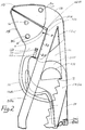
Im folgenden wird die Erfindung anhand einer lediglich ein Ausführungsbeispiel darstellenden Zeichnung näher erläutert; es zeigt
- Fig.1 ein /-e erfindungsgemäßes /-e Kompaktschloßwerkzeug / -zange in Seitenansicht mit den Konturen der wesentlichen Bestandteile, wobei die Zuordnung von Bezugzeichen mit Strich- und Strichpunktlinien unterstützt wurde,
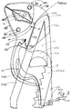
- Fig.2 einen vergrößerten Abschnitt von Fig.1, wobei Einzelheiten deutlicher erkennbar sind, insbesondere Backen mit Aufsteckbacken und die Sensortechnik mit ihrer Krafteinleitungsmechanik sowie ein Federelement mit seiner Befestigung am Oberhebel und seiner, damit auch der des Oberhebels, für die Sollstellung relevante Federabstützung gegen den Haltebügel an der Unterbacke in Ruhe und
- Fig.3 einen vergrößerten Abschnitt der Seitenansicht von Fig.1 und ähnlich Fig.2 mit gesonderter Darstellung von Aufsteckbacken mit Füllstücken für profilierte, mit Brennerloch ausgestattete Backen sowie mit angeformtem Werkzeug und mit Sensorbestücktem Gegenüber, einschließlich dessen Beaufschlagungsmechanismus.
- 1 shows a compact lock tool / pliers according to the invention in side view with the contours of the essential components, the assignment of reference numerals being supported with dash and semicolon lines,
- 2 shows an enlarged section of FIG. 1, details being more clearly recognizable, in particular jaws with slip-on jaws and the sensor technology with its force introduction mechanism, and a spring element with its attachment to the upper lever and its spring support relevant for the desired position against the desired position the bracket on the lower jaw at rest and
- 3 shows an enlarged section of the side view of FIG. 1 and similar to FIG. 2 with a separate illustration of plug-on jaws with filler pieces for profiled jaws equipped with a burner hole, as well as with a molded tool and with a sensor-equipped counterpart, including its loading mechanism.
Claims (9)
dadurch gekennzeichnet,
characterized,
Applications Claiming Priority (2)
| Application Number | Priority Date | Filing Date | Title |
|---|---|---|---|
| DE1996105295 DE19605295A1 (en) | 1996-02-14 | 1996-02-14 | Compact continuously adjustable pliers for measuring and gripping |
| DE19605295 | 1996-02-14 |
Publications (1)
| Publication Number | Publication Date |
|---|---|
| EP0790102A1 true EP0790102A1 (en) | 1997-08-20 |
Family
ID=7785287
Family Applications (1)
| Application Number | Title | Priority Date | Filing Date |
|---|---|---|---|
| EP97102207A Withdrawn EP0790102A1 (en) | 1996-02-14 | 1997-02-13 | Compact guide rail lock implement or plier with roughly and fine stepless parallel to upper gripper jaw shifting adjustment of lower gripper jaw with unishape guide block as well as with integrated measuring arrangement |
Country Status (2)
| Country | Link |
|---|---|
| EP (1) | EP0790102A1 (en) |
| DE (1) | DE19605295A1 (en) |
Citations (5)
| Publication number | Priority date | Publication date | Assignee | Title |
|---|---|---|---|---|
| US1508510A (en) * | 1923-03-17 | 1924-09-16 | Charles S Edwards | Pliers |
| DE1478951A1 (en) * | 1962-08-24 | 1969-10-30 | Carl Kuhbier | Pliers |
| US3534641A (en) * | 1968-08-09 | 1970-10-20 | Donald Le Duc | Pliers with slidable jaw actuation by claw lever means |
| DE3102390A1 (en) * | 1981-01-24 | 1983-01-05 | Fritz 6703 Limburgerhof Knebel | Waterpump pliers |
| EP0421107A2 (en) * | 1989-09-04 | 1991-04-10 | Knipex-Werk C. Gustav Putsch | Pliers |
-
1996
- 1996-02-14 DE DE1996105295 patent/DE19605295A1/en not_active Withdrawn
-
1997
- 1997-02-13 EP EP97102207A patent/EP0790102A1/en not_active Withdrawn
Patent Citations (5)
| Publication number | Priority date | Publication date | Assignee | Title |
|---|---|---|---|---|
| US1508510A (en) * | 1923-03-17 | 1924-09-16 | Charles S Edwards | Pliers |
| DE1478951A1 (en) * | 1962-08-24 | 1969-10-30 | Carl Kuhbier | Pliers |
| US3534641A (en) * | 1968-08-09 | 1970-10-20 | Donald Le Duc | Pliers with slidable jaw actuation by claw lever means |
| DE3102390A1 (en) * | 1981-01-24 | 1983-01-05 | Fritz 6703 Limburgerhof Knebel | Waterpump pliers |
| EP0421107A2 (en) * | 1989-09-04 | 1991-04-10 | Knipex-Werk C. Gustav Putsch | Pliers |
Also Published As
| Publication number | Publication date |
|---|---|
| DE19605295A1 (en) | 1997-01-23 |
Similar Documents
| Publication | Publication Date | Title |
|---|---|---|
| DE2125172C3 (en) | Press such as extrusion press, drawing press or the like driven by a crank drive | |
| DE4117305C2 (en) | Pliers for gripping and / or pressing processed objects | |
| DE3739173A1 (en) | METHOD AND DEVICE FOR BENDING WORKPIECES | |
| DE202018006658U1 (en) | Press jaws and press tongs with two tong jaws | |
| EP0421107A2 (en) | Pliers | |
| DE2755482C2 (en) | ||
| DE2844065A1 (en) | HAND-HELD TOOL FOR INSERTING FASTENERS | |
| DE202010006494U1 (en) | Hand-operated clamping tools | |
| EP0305767A2 (en) | Carriage clamping means for machine tools | |
| EP0790102A1 (en) | Compact guide rail lock implement or plier with roughly and fine stepless parallel to upper gripper jaw shifting adjustment of lower gripper jaw with unishape guide block as well as with integrated measuring arrangement | |
| DE2647550A1 (en) | DEVICE FOR TAILOR-MADE ANGLE OF THE WHEELS OF LARGE-AREA SHEET CUTS | |
| DE3136879A1 (en) | Lever clamp | |
| DE202006020729U1 (en) | Adjustment device for mounting racks | |
| EP0087630B1 (en) | Tool of the pliers or wrench type, in particular universal pliers | |
| DE3411459A1 (en) | TOOLS FOR CRIMPING, CUTTING, PRESSING OR THE LIKE. | |
| EP0058827B1 (en) | Lever tool | |
| DE4338179C2 (en) | Lever clamp | |
| DE4030777A1 (en) | Press brake system with a straightening device for plate-shaped workpieces | |
| EP0672376B1 (en) | Window cleaning implement | |
| DE1925988A1 (en) | Process for the production of metallic screw blades, the machine enabling it to be used and screw blades obtained by this process | |
| DE2607986C3 (en) | Jig | |
| DE141926C (en) | ||
| DE10132481C2 (en) | Tool for the production of venetian chains | |
| DE4209259C2 (en) | Bending device | |
| DE358664C (en) | Stapling pliers for connecting drive belts |
Legal Events
| Date | Code | Title | Description |
|---|---|---|---|
| PUAI | Public reference made under article 153(3) epc to a published international application that has entered the european phase |
Free format text: ORIGINAL CODE: 0009012 |
|
| AK | Designated contracting states |
Kind code of ref document: A1 Designated state(s): AT ES FR GB IT NL SE |
|
| STAA | Information on the status of an ep patent application or granted ep patent |
Free format text: STATUS: THE APPLICATION IS DEEMED TO BE WITHDRAWN |
|
| 18D | Application deemed to be withdrawn |
Effective date: 19980221 |