EP0789247B1 - Verfahren und Vorrichtung zur Erkennung und Erfassung der Spannungspulsbreite einer Kraftfahrzeugeinspritzanlage - Google Patents
Verfahren und Vorrichtung zur Erkennung und Erfassung der Spannungspulsbreite einer Kraftfahrzeugeinspritzanlage Download PDFInfo
- Publication number
- EP0789247B1 EP0789247B1 EP97102206A EP97102206A EP0789247B1 EP 0789247 B1 EP0789247 B1 EP 0789247B1 EP 97102206 A EP97102206 A EP 97102206A EP 97102206 A EP97102206 A EP 97102206A EP 0789247 B1 EP0789247 B1 EP 0789247B1
- Authority
- EP
- European Patent Office
- Prior art keywords
- event
- signal
- pulse
- timer
- time
- Prior art date
- Legal status (The legal status is an assumption and is not a legal conclusion. Google has not performed a legal analysis and makes no representation as to the accuracy of the status listed.)
- Expired - Lifetime
Links
- 238000000034 method Methods 0.000 title claims description 14
- 239000000446 fuel Substances 0.000 title description 41
- 238000001514 detection method Methods 0.000 title description 3
- 230000006870 function Effects 0.000 claims description 8
- 238000001914 filtration Methods 0.000 claims description 5
- 238000012544 monitoring process Methods 0.000 claims 1
- 230000000630 rising effect Effects 0.000 description 12
- QVGXLLKOCUKJST-UHFFFAOYSA-N atomic oxygen Chemical compound [O] QVGXLLKOCUKJST-UHFFFAOYSA-N 0.000 description 7
- 230000001939 inductive effect Effects 0.000 description 7
- 229910052760 oxygen Inorganic materials 0.000 description 7
- 239000001301 oxygen Substances 0.000 description 7
- 239000000523 sample Substances 0.000 description 5
- 230000001960 triggered effect Effects 0.000 description 5
- 230000008901 benefit Effects 0.000 description 4
- 238000005259 measurement Methods 0.000 description 4
- 230000004044 response Effects 0.000 description 4
- 238000012360 testing method Methods 0.000 description 4
- 230000009471 action Effects 0.000 description 3
- 238000002485 combustion reaction Methods 0.000 description 3
- 230000007423 decrease Effects 0.000 description 3
- 238000010586 diagram Methods 0.000 description 3
- 239000000203 mixture Substances 0.000 description 3
- 230000008569 process Effects 0.000 description 3
- 230000001133 acceleration Effects 0.000 description 2
- 230000004075 alteration Effects 0.000 description 2
- 238000003745 diagnosis Methods 0.000 description 2
- 238000002347 injection Methods 0.000 description 2
- 239000007924 injection Substances 0.000 description 2
- 238000012986 modification Methods 0.000 description 2
- 230000004048 modification Effects 0.000 description 2
- 238000012545 processing Methods 0.000 description 2
- 230000008439 repair process Effects 0.000 description 2
- 230000004913 activation Effects 0.000 description 1
- 230000003466 anti-cipated effect Effects 0.000 description 1
- 239000006227 byproduct Substances 0.000 description 1
- 230000001143 conditioned effect Effects 0.000 description 1
- 230000003750 conditioning effect Effects 0.000 description 1
- 230000000737 periodic effect Effects 0.000 description 1
Images


Classifications
-
- G—PHYSICS
- G01—MEASURING; TESTING
- G01R—MEASURING ELECTRIC VARIABLES; MEASURING MAGNETIC VARIABLES
- G01R29/00—Arrangements for measuring or indicating electric quantities not covered by groups G01R19/00 - G01R27/00
- G01R29/02—Measuring characteristics of individual pulses, e.g. deviation from pulse flatness, rise time or duration
Definitions
- the present relation relates to a system for detecting the event time of pulse events of variable duration appearing in an input signal, each of the pulse events having two or more pulses, the system comprising signal ranging means for receiving the input signal and generating therefrom an adjusted input signal, first comparator means for comparing an adjusted input signal and a first threshold voltage magnitude to generate a first event signal each time a first pulse appearing on the adjusted input signal has a voltage magnitude exceeding the first threshold voltage magnitude, the first event signal having a leading edge and a trailing edge defining a pulse width corresponding to the pulse width of the first pulse, second comparator means for comparing an adjusted input signal and a second threshold voltage magnitude to generate a second event signal each time a second pulse appearing on the adjusted input signal has a voltage magnitude exceeding the second threshold voltage magnitude, the second event signal having a leading edge and a trailing edge defining a pulse width corresponding to the pulse width of the second pulse, and microcontroller means.
- the present invention relates also to a method for detecting the event time of pulse events of variable duration appearing in an input signal, each of the pulse events having two or more pulses, the method comprising the steps of:
- the injector driving signal is formed by a pulse train which comprises two or more pulses of different height. This injector driving signal is compared with a first reference voltage at a first comparator.
- the injector driving signal is processed by means of a conventional voltage divider comprising resistors and compared with a second, higher reference voltage at a second comparator.
- the first (lower) reference voltage is formed by dividing the second (higher) reference voltage by means of a conventional voltage dividing circuit comprising resistors.
- the first comparator is said to generate a fly-back voltage output.
- the output of the second comparator is processed with a one-shot circuit.
- the occurence of a one-shot therefore, indicates a high level pulse component, whereas the output of the first comparator reflects the occurence of low level pulse components.
- the output of the one-shot circuit and the fly-back voltage from the first comparator indicating low-level pulse components are compounded with a logical circuit.
- a lowered injector driving signal is compared with a high-reference voltage and the original injector driving signal is compared with a lowered reference voltage.
- the first and second comparators may distinguish between pulse components of different height.
- the high-level components define the beginning and end of the whole pulse train.
- the output of the second comparator reflects the high-level pulse components, whereas the output of the first comparator reflects the low-level pulse components.
- a clock-triggered counter measures the time in which the logical circuit does not generate an output, that is when neither a high-level nor a low-level pulse component is detected. If this time exceeds a specified time, a time width to be output from a flip-flop is processed with a microcomputer whereby injector driving pulse width is said to be securable. It is further stated that a diagnosis for the injector is performable with the same measuring device, however without providing any details thereof.
- US-A-5,107,426 discloses a hand-held apparatus for in-vehicle testing of electronic fuel injection systems.
- This apparatus is said to be adapted to receive signals from and supply test signals to injection systems under test by means of a hand-held probe connected to one of only a small number of test sockets on said apparatus.
- the apparatus comprises a voltage pulse width timer adapted to time voltage pulse width of predetermined pulse trains supplied to vehicle engine fuel injectors, alphanumeric display means for displaying parameters including ohms, volts and time measured by said apparatus.
- the present invention relates generally to electronic signal measurement apparatus, and more particularly to a system for detection and acquisition of automotive fuel injector voltage signal pulse width regardless of the fuel injector type.
- a signal of particular interest is the voltage signal of a fuel injector, more specifically, the pulse width of the voltage signal as detected at the fuel injector.
- Fuel injectors of an automobile receives periodic voltage pulses of a duration as specified by the computer module of the automobile.
- the computer module receives a signal from the oxygen sensor indicating the amount of oxygen remaining after combustion of the air-fuel mixture.
- the computer module adjusts the amount of fuel to be injected by the injectors by varying the pulse width of the voltage signal sent to the fuel injectors.
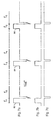
- Figs. 1a - 1d illustrate four feed-side controlled pulse types that may be detected at the fuel injector voltage terminals. The ground symbols serves as a reference point for the depicted voltage signals.
- Fig. 1a a Port Fuel Injector (PFI) type pulse 10 comprising of a base pulse 12 and a kickback pulse 14 is illustrated.
- Fig. 1b illustrates a "peak & hold" or "current limited” pulse 16 comprising of a base pulse 18 and two kickback pulses as indicated at 20 and 22.
- Fig. PFI Port Fuel Injector
- FIG. 1c illustrates a Modulated with One Kickback pulse 24 comprising of one base pulse 26 immediately followed by two (or more) shorter pulses (28 and 30) and a kickback pulse 32.
- a Modulated with Two Kickback pulse 34 is comprised of a base pulse 36 followed by a kickback pulse 38, two (or more) shorter pulses (40 and 42), and another kickback pulse 44. Note that the kickback pulses typically are much larger than the base pulses and they are illustrated with broken dots to emphasize the voltage differences.
- Figs. 4a - 4d illustrate four ground-side pulse types that may be detected at a fuel injector.
- Fig. 4a there is a PFI type pulse 46 with a downward base pulse 48 followed by a kickback pulse 50.
- Fig. 4b there is a "peak & hold" or “limited current" pulse 52 comprising of a base pulse 54 followed by two kickback pulses (56 and 58).
- Fig. 4c illustrates a Modulated with One Kickback pulse 60 with a base pulse 62 followed immediately by two (or more) shorter pulses (64 and 66) and a kickback pulse 68.
- Fig. 4a illustrate four ground-side pulse types that may be detected at a fuel injector.
- Fig. 4a there is a PFI type pulse 46 with a downward base pulse 48 followed by a kickback pulse 50.
- Fig. 4b there is a "peak & hold" or “limited current” pulse 52 comprising of a base pulse 54 followed by two kickback pulses
- a Modulated with Two Kickback pulse 70 is comprised of a base pulse 72 followed by a kickback pulse 74, two (or more) shorter pulses (76 and 78) and another kickback pulse 80. All of the detected kickback pulses are byproducts of the operation of the fuel injector coil and are further explained below.
- the number of 'shorter' base pulses on all modulated injectors (1 or 2 kickbacks, feed-side or ground-side) varies with the duration of the total injector event.
- the duration of the first (wider) base pulse is relatively fixed, and that is the amount of time it takes for the current flowing into the injector to actuate the pintle. To maintain the pintle in the actuated state allowing a greater amount of fuel injected, shorter base pulses are provided.
- the figures of the voltage signals of the moduled injectors depict the waveforms at one particular pulse width (around 2.5 ms).
- the wider base pulse is generally fixed, and the number of shorter base pulses increases or decreases to adjust the total pulse width.
- a positive voltage signal is applied by the vehicle's computer module which causes a current to flow through the injector coil to produce a magnetic field that activates a pintle to allow fuel to be injected through a valve opening into the combustion chamber of a cylinder.
- the pulse width of the voltage signal corresponds to the duration or amount of time the pintle remains actuated and therefore the amount of fuel injected into the cylinder. If a high level of oxygen remains after combustion (indicating a 'lean' air-fuel mixture), the oxygen sensor detects and reports such a condition to the computer module and the computer module in response increases the pulse width of the voltage signal sent to the fuel injector and thereby increases the amount of fuel injected into the cylinder.
- the computer module in response to such condition decreases the duration of the voltage signal to decrease the amount of fuel injected into the cylinder.
- the computer module Upon turning off the voltage to the injector coil (after the falling edge of the pulse), there is a kickback pulse having a magnitude far exceeding the magnitude of the base pulse due to the collapsing magnetic field within the injector.
- Ground-side controlled injectors operate in likewise manner as that of the feed-side controlled injectors with the difference being that the injectors are supplied with constant voltage by the vehicle's electrical system, and the computer module supplies or removes a ground path to the injector to control current flow.
- the pintle is actuated to allow fuel to be injected into the cylinder.
- the computer module receives other input signals that may cause the computer module to adjust the pulse width of the voltage signal to the fuel injectors in response to the input signals.
- the computer module receives other input signals that may cause the computer module to adjust the pulse width of the voltage signal to the fuel injectors in response to the input signals.
- Prior art measurement systems for observation of injector voltage pulse width modulation proves to be difficult to use or inaccurate.
- Such systems include oscilloscopes, digital multimeters with capability for measuring pulse width, and digital multimeters with special capability for measuring fuel injector pulse width.
- oscilloscopes the user must manually synchronize the voltage signal from the injector and manually measure and calculate the start and stop times of the pulse event in order to obtain the pulse width. This is a very time consuming process prone to mistakes in the measurement of the pulses.
- the pulse width of a fuel injector voltage signal generally comprises one or more base pulses and one or more inductor kickback pulses.
- a single-point voltage reference measures either the base pulse width or the kickback pulse width but not both, and is therefore unable to correctly detect the true pulse width.
- Prior art digital multimeters featuring capability for measuring fuel injector pulse width require the user to first identify whether the injector is a feed-side controlled or ground side controlled injector before connecting the probes of the multimeter to the injector. This additional step of identifying the injector type prior to the using of the multimeter hinders efficient diagnosis of an automobile and requires the user to have a higher knowledge level of the fuel injector system. Additionally, some of these multimeters use pattern matching to identify the pulse type. However, pattern matching methods are unable to detect new pulse types that may be later developed by the automobile manufacturers.
- the adjusted input signal has voltage levels within a predetermined voltage range
- graphical display means are provided
- analog-to-digital converter means for assembling the adjusted input signal to generate digital values representative thereof are provided
- the microcontroller means receives the digital values and determines the first threshold voltage magnitude as a function of a first magnitude of the digital values, and the second threshold voltage magnitude as a function of a second magnitude of the digital values
- the microcontroller receives the first event signal and the second event signal and monitors the occurrence of each of the first event signal and the second event signal
- the microcontroller means calculates the event time of the pulse event as a function of the occurrence of the first event signal and the second event signal, and passes event time to the graphical display means for display.
- the present invention is embodied in the form a hand-held instrument which includes signal detection circuits for capturing the rising (or leading) and falling (or trailing) edges of an input signal having positive and negative voltage swings.
- signal detection circuits for capturing the rising (or leading) and falling (or trailing) edges of an input signal having positive and negative voltage swings.
- a corresponding software routine is executed to carry out the process of measuring the pulse width of a pulse of the input signal.
- the measured pulse width is then displayed in numerical and/or histogramic formats.
- An important advantage of the present invention is that the type of fuel injector signal is automatically detected.
- Another advantage of the present invention is that the user is not required to have any knowledge regarding the type of the fuel injector in order to operate the apparatus embodying the present invention.
- Still another advantage of the present invention is that new pulse types are easily detected without resorting to pattern matching or templates.
- a typical feed-side controlled PFI voltage signal as detected at the voltage terminals of a fuel injector is shown here with several pulses over several time periods.
- the pulses, 82, 84, and 86 are in time periods t1, t3, and t5. Pulses 82 and 84 are separated by time period t2, and pulses 84 and 86 are separated by time period t4.
- the event time could range from 2 ms to 3 ms at 1000 RPM (idle) engine speed. Under heavy acceleration (high engine load), the event time typically ranges around 20 ms at about 1000 RPM to 2000 RPM.
- the typical time between events at about 1000 RPM is around 120 ms (based on a typical 4-stroke spark-ignition engine cycle). Under rapid acceleration, the time between events are shortened to a certain extent. Nevertheless, the time lapsed between events is much greater than the event time.
- the start of a pulse event is marked by the occurrence of a base pulse edge after an idle period and the end of a pulse event is marked by the occurrence of a kickback pulse edge followed by an idle period.
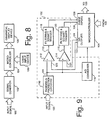
- a generalized block diagram illustrating the major subsystems of the preferred embodiment of the present invention includes a signal conditioner 102 for receiving and conditioning the input signal 100, a microcontroller 104 for receiving user signals from a user input device 106 and the conditioned input signals from the signal conditioner 102, and a graphical display device 108 for displaying processed signals received from the microcontroller 104.
- the signal conditioner 102 is comprised of a Ranging and Protection circuitry 110, comparators 112 and 114, and Filtering and Triggering circuits 118 and 120.
- the protection circuitry protects the circuit from excessive power or power surges and the ranging circuitry adjusts the input voltage to a level acceptable to the downstream circuitry.
- a typical acceptable signal level is within the range of plus/minus 2.5 volts.
- the adjusted input signal 101 from the Ranging and Protection circuitry 110 is then sampled by the analog-to-digital converter 116 to provide digital values for input to the microcontroller.
- the digital sample values provide a basis for the microcontroller to determine the voltage swing of the adjusted input signal appearing on line 101, and to generate reference threshold voltages at digital/analog output ports 122 and 124 for input to comparator 112 at 123 and comparator 114 at 125.
- the reference threshold voltages are typically a positive and a negative threshold voltage that the adjusted input signal on line 101 must exceed in order to cause comparator 112 to generate a signal on lines 113 or comparator 114 to generate a signal on line 115. More specifically, comparator 112 detects the base portion of the adjusted input signal appearing on line 101. Figs.
- FIG. 2a-2d illustrate the detected base portions of the corresponding input signals depicted at Figs. 1a-1d
- Figs 5a-5d illustrate the detected base portion for the corresponding input waveforms of Figs. 4a-4d
- Fig. 7b depicts the base portion of Fig. 7a.
- Comparator 114 detects the inductive kickback portion of the adjusted input signal.
- Figs. 3a-3d show the detected inductive kickback portions for the corresponding input waveforms of Figs. 1a-1d
- Figs. 6a-6d show the detected inductive kickback portions for the corresponding input signals of Figs. 4a-4d
- Fig. 7c illustrates the detected kickback portion of the signal depicted by Fig. 7a.
- the signals generated by the comparators are filtered and the signal edges are made sharp by the Filtering and Trigger circuitries 118 and 120.
- the signal is then passed on to event input ports 126 and 128 of the microcontroller 104. Note that the threshold voltages are set only once for a particular input signal.
- the microcontroller 104 evaluates the digital sample values received from A/D converter 116 over a certain period of time, determines whether the voltage signal is a feed-side controlled signal or a ground-side controlled signal, and sets the threshold voltage levels that the adjusted input voltage on line 101 must exceed in order to be detected as a rising edge (or a falling edge).
- the microcontroller looks at the digital sample values representing the adjusted input signal appearing on line 101.
- a feed-side signal is typically at near-zero voltage while the injector is 'off', rises to vehicle battery voltage when 'on' (reflecting the base pulse(s)), and drops to about negative 30 to 40 volts due to the inductive kickback spikes.
- the microcontroller can thus determine a feed-side signal from the maximum and minimum voltages observed (typically +12 volts to around -40 volts).
- the observed signal is typically at vehicle battery voltage while 'off', drops to near-zero voltage while 'on', and inductive kickbacks result in peaks near positive 50 to 60 volts.
- the microcontroller is able to determine a ground-side signal by observing signals in the range of 0 volt to +60 volts.
- the microcontroller 104 After determining the injector type, the microcontroller 104 then sets an appropriate threshold voltage for comparator 112 and a threshold voltage for comparator 114 where each threshold voltage is at a sufficient level to identify the occurrence of an edge. Should the adjusted input signal on line 101 exceed either of the threshold voltages it will cause the corresponding comparator to generate a signal which is then filtered and pulse shaped by the Filtering and Trigger circuitry 118 or 120. The microcontroller then receives the processed signal at event input port 126 or 128 as a signal event.
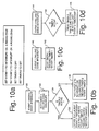
- the microcontroller upon receiving the event signals identifies a rising edge or a falling edge and executes the corresponding software routine depicted in the flow charts of Figs. 10a-10d and 11a-11d in accordance with another aspect of the present invention.
- two count-down timers timer1 and timer2 are maintained where a timer1 or timer2 interrupt is triggered when the corresponding count-down timer has reached zero.
- Timer1 is used to determine the end of an event
- timer2 is used to measure the pulse width.
- the two event signals are referred to as event1 and event2 signals in the following description where event1 refers to the base portion of a signal and event2 refers to the kickback portion.
- the microcontroller having already determined the input voltage signal as a feed-side controlled or a ground-side controlled voltage signal selects the corresponding set of software routines to process the signals received from the event input ports.
- the initialization step sets event1 and event2 to interrupt on rising edges (meaning that only a rising edge will trigger a corresponding software routine and no action will be taken on a falling edge), and both timers are turned off.
- the event1 interrupt is reset to trigger on a falling edge as indicated at 132.
- timer2 is not active (138)
- event2 is set to interrupt on falling edges, timer2 is initialized and started. If timer2 has been active (136), the last recorded time stamp for the occurrence of event2 is taken as the pulse width and is transferred to storage for later use. Timer2 is then cleared, initialized, and restarted again.
- timer1 is stopped, reloaded to expire at some point in the future where no further event interrupts are expected, and restarted as indicated at box 142.
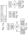
- the routine as depicted in Fig. 10d is executed. If timer2 is active, the time of timer2 is recorded as the latest event2 time-stamp. If timer2 is not active, no action is taken. Note that no action is taken for an event2 rising edge interrupt.
- timer1 In the event that a timer1 interrupt occurs due to the fact that timer1 has counted down to zero, timer1 is stopped and event1 is reset to trigger on a rising edge.
- the occurrence of timer1 interrupt indicates that a prescribed amount of time has elapsed without receiving any event1 edges, and so the next rising edge indicates the start of a new pulse event.
- timer1 is typically initialized to 5 ms and timer2 is typically initialized to 21 ms.
- the algorithm is the same as that of the algorithm for a feed-side controlled signal except that what was triggered on rising edges now triggers on falling edges and what was triggered on falling edges now triggers on rising edges.
- the detected pulse width stored in memory is processed and displayed on the monitor.
- the resulting pulse width is either displayed numerically or in a histograph showing pulse width variation over time.
- average pulse width over specified duration can be calculated and displayed.
- the present invention forms part of a graphing, digital multimeter and diagnostic database instrument manufactured by Balco, a division of Snap-on Incorporated, of San Jose, California. It will be appreciated, however, that the invention could be embodied as a stand-alone unit or as a component part of another indicator or diagnostic system.
Landscapes
- Physics & Mathematics (AREA)
- General Physics & Mathematics (AREA)
- Combined Controls Of Internal Combustion Engines (AREA)
- Measuring Volume Flow (AREA)
- Investigating Or Analyzing Materials Using Thermal Means (AREA)
Claims (18)
- System zum Erfassen der Ereigniszeit von Pulsereignissen (10; 16; 24; 34; 46; 52; 60; 70) variabler Dauer, die in einem Eingangssignal (100) auftreten, wobei jedes der Pulsereignisse (10; 16; 24; 34; 46; 52; 60; 70) zwei oder mehr Pulse aufweist, wobei das System aufweist:gekennzeichnet durch:Signalausrichtungsmittel (110) zum Empfangen des Eingangssignals (100) und zum daraus Erzeugen eines eingestellten Eingangssignals (101);erste Komparatormittel (112) zum Vergleichen des eingestellten Eingangssignals (101) und einer ersten Schwellenspannungsgröße (123), um jedes mal dann ein erstes Ereignissignal (113) zu erzeugen, wenn ein erster Puls (12; 18; 26; 36; 48; 54; 62; 72), der an dem eingestellten Eingangssignal (101) erscheint, eine Spannungsgröße besitzt, die die erste Schwellenwertspannungsgröße (123) überschreitet, wobei das erste Ereignissignal (113) eine Anstiegsflanke und eine Abfallflanke aufweist, die eine Pulsbreite definieren, die der Pulsbreite des ersten Pulses (12; 18; 26; 36; 48; 54; 62; 72) entspricht;zweite Komparatormittel (114) zum Vergleichen des eingestellten Eingangssignals (101) und einer zweiten Schwellenspannungsgröße (124), um jedesmal dann ein zweites Ereignissignal (115) zu erzeugen, wenn ein zweiter Puls (14; 20, 22; 32; 38, 44; 50; 56, 58; 68; 74, 80), der an dem eingestellten Eingangssignal (101) erscheint, eine Spannungsgröße besitzt, die die zweite Schwellenspannungsgröße (125) überschreitet, wobei das zweite Ereignissignal (115) eine Anstiegsflanke und eine Abfallflanke aufweist, die eine Pulsbreite definieren, die der Pulsbreite des zweiten Pulses (14; 20, 22; 32; 38, 44; 50; 56, 58; 68; 74, 80) entspricht; undMikrocontrollermittel (104),die Tatsache, daß die Signalausrichtungsmittel das eingestellte Eingangssignal (101) mit Spannungspegeln innerhalb eines vorbestimmten Spannungsbereiches erzeugen;graphische Anzeigemittel (108);Analog/Digital-Wandlermittel (116) zum Assemblieren des derartigen eingestellten Eingangssignals (101), um digitale Werte zu erzeugen, die das eingestellte Eingangssignal (101) darstellen;die Tatsache, daß die Mikrocontrollermittel (104) die digitalen Werte empfangen und die erste Schwellenspannungsgröße (123) als eine Funktion einer ersten Größe der digitalen Werte bestimmen, und die zweite Schwellenspannungsgröße (125) als eine Funktion einer zweiten Größe der digitalen Werte bestimmen, um das erste Ereignissignal (113) und das zweite Ereignissignal (115) zu empfangen, zum Zwecke des Überwachens des Auftretens des ersten Ereignissignals (113) als auch des zweiten Ereignissignals; unddie Tatsache, daß die Mikrocontrollermittel (115) die Ereigniszeit des Pulsereignisses als eine Funktion des Auftretens des ersten Ereignissignals (113) und des zweiten Ereignissignals (115) berechnen und die Ereigniszeit zur Anzeige an die graphischen Anzeigemittel (108) übergeben.
- System nach Anspruch 1, dadurch gekennzeichnet, daß die Mikrocontrollermittel (104) einen oder mehrere Zeitgeber koordinieren, um bei Empfang des ersten Ereignissignals (113) und des zweiten Ereignissignals (115), die jeweils eine Anstiegsflanke und eine Abfallflanke aufweisen, die Ereigniszeit für ein Pulsereignis zu messen.
- System nach Anspruch 1 oder. Anspruch 2, dadurch gekennzeichnet, daß die Mikrocontrollermittel (104) vor dem Messen der Ereigniszeit einen ersten Zeitgeber in einen inaktiven Zustand initialisieren, einen zweiten Zeitgeber in einen inaktiven Zustand initialisieren, einen ersten Interrupt so initialisieren, daß er bei Empfang der Anstiegsflanke eines ersten Ereignissignals (113) auftritt, und einen zweiten Interrupt so initialisieren, daß er bei Empfang der Anstiegsflanke eines zweiten Ereignissignals (115) auftritt.
- System nach Anspruch 3, dadurch gekennzeichnet, daß die Mikrocontrollermittel (104) bei Empfang des ersten Interrupts, der den Empfang der Anstiegsflanke eines ersten Ereignissignals (113) anzeigt, den ersten Interrupt so einstellen, daß er bei der Abfallflanke eines ersten Ereignissignals (113) auftritt; daß die Mikrocontrollermittel (104), dann, wenn der zweite Zeitgeber nicht aktiv ist, den zweiten Interrupt so einstellen, daß er bei Empfang der Anstiegsflanke eines zweiten Ereignissignals (115) auftritt, und den zweiten Zeitgeber neu laden und neu starten; und daß die Mikrocontrollermittel (104) dann, wenn der zweite Zeitgeber aktiv ist, eine Aufzeichnung der abgelaufenen Zeit bestimmen, und zwar als die Ereigniszeit für das Pulsereignis, und den zweiten Zeitgeber neu laden und starten.
- System nach Anspruch 4, dadurch gekennzeichnet, daß die Mikrocontrollermittel (104) bei Empfang des ersten Interrupt, der den Empfang der Abfallflanke des ersten Ereignissignals (113) anzeigt, den ersten Zeitgeber neu laden und neu starten, wobei der erste Zeitgeber das Ende eines Pulsereignisses bestimmt, indem er von einem voreingestellten Zeitbetrag abwärts zählt und veranlaßt, daß ein erster Zeitgeber-Interrupt auftritt, wenn der erste Zeitgeber bis auf Null herunterzählt.
- System nach Anspruch 5, dadurch gekennzeichnet, daß die Mikrocontrollermittel (104) bei Empfang des zweiten Interrupts, der den Empfang der Anstiegsflanke eines zweiten Ereignissignals anzeigt, dann, wenn der zweite Zeitgeber aktiv ist, die Aufzeichnung der abgelaufenen Zeit mit dem zweiten Zeitgeber aktualisiert.
- System nach Anspruch 6, dadurch gekennzeichnet, daß die Mikrocontrollermittel (104) bei Empfang des ersten Zeitgeber-Interrupt den ersten Interrupt so einstellen, daß er bei Empfang der Anstiegsflanke eines ersten Ereignissignals auftritt, und den ersten Zeitgeber anhalten.
- System nach einem der Ansprüche 1 bis 7, dadurch gekennzeichnet, daß der erste Puls (12; 18; 26; 36; 48; 54; 62; 72) ein Basispuls des Pulsereignisses (10; 16; 24; 34; 46; 52; 60; 70) ist und daß der zweite Puls (14; 20, 22; 32; 38, 44; 50; 56, 58; 68; 74, 80) ein Rückstoßpuls des Pulsereignisses (10; 16; 24; 34; 46; 52; 60; 70) ist.
- System nach einem der Ansprüche 1 bis 8, gekennzeichnet durch Benutzereingabemittel (106), die betriebsmäßig mit den Mikrocontrollermitteln (104) verbunden sind, zum Spezifizieren von Eingangsparametern einschließlich von Anzeigemodi.
- System nach einem der Ansprüche 1 bis 9, gekennzeichnet durch erste Filtermittel (118), die die ersten Komparatormittel (112) mit den Mikrocontrollermitteln (104) betriebsmäßig verbinden, zum Filtern des ersten Ereignissignals (113), bevor das erste Ereignissignal (113) an die Mikroprozessormittel (104) übergeben wird.
- System nach einem der Ansprüche 1 bis 10, gekennzeichnet durch zweite Filtermittel (120), die die zweiten Komparatormittel (114) mit den Mikrocontrollermitteln (104) betriebsmäßig verbinden, zum Filtern des zweiten Ereignissignals (115) bevor das zweite Ereignissignal (115) an die Mikrocontrollermittel (104) übergeben wird.
- System nach einem der Ansprüche 1 bis 11, gekennzeichnet durch erste Schmitt-Triggermittel (118), die die ersten Komparatormittel (112) mit den Mikrocontrollermitteln (104) betriebsmäßig verbinden, zum Schärfen der Flanke des ersten Ereignissignals (113), bevor das erste Ereignissignal (113) an die Mikrocontrollermittel (104) übergeben wird.
- System nach einem der Ansprüche 1 bis 12, gekennzeichnet durch zweite Schmitt-Triggermittel (120), die die zweiten Komparatormittel (112) mit den Mikrocontrollermitteln (104) betriebsmäßig verbinden, zum Schärfen der Flanke des zweiten Ereignissignals (115), bevor das zweite Ereignissignal (115) an die Mikrocontrollermittel (104) übergeben wird.
- System nach einem der Ansprüche 1 bis 13, dadurch gekennzeichnet, daß die Signalausrichtungsmittel (110) Schaltkreise zum Schaltungsschutz aufweisen, um zu verhindern, daß das Eingangssignal (100) das System beschädigt.
- System nach einem der Ansprüche 1 bis 14, gekennzeichnet durch eine Speichereinheit zum Speichern der Ereigniszeit der Pulsereignisse (10; 16; 24; 34; 46; 52; 60; 70).
- System nach Anspruch 15, dadurch gekennzeichnet, daß die Mikrocontrollermittel (104) aus den Ereigniszeitwerten in der Speichereinheit einen mittleren Ereigniszeitwert über eine spezifizierte Zeitspanne berechnen und den mittleren Ereigniszeitwert zur Anzeige an die graphischen Anzeigemittel (108) übergeben.
- Verfahren zum Erfassen der Ereigniszeit von Pulsereignissen (10; 16; 24; 34; 46; 52; 60; 70) variabler Dauer, die in einem Eingangssignal (100) erscheinen, wobei jedes der Pulsereignisse (10; 16; 24; 34; 46; 52; 60; 70) zwei oder mehr Pulse aufweist, wobei das Verfahren die Schritte aufweist:gekennzeichnet durchEmpfangen und Einstellen des Eingangssignals (100), um ein eingestelltes Eingangssignal (101) zu bilden; undBilden einer ersten Schwellenspannungsgröße (123) und einer zweiten Schwellenspannungsgröße (125); undVergleichen des eingestellten Eingangssignals (101) und der ersten Schwellenspannungsgröße (123), um jedesmal dann, wenn das eingestellte Eingangssignal (101) die erste Schwellenspannungsgröße (123) überschreitet, ein erstes Ereignissignal (113) zu erzeugen, und Vergleichen des eingestellten Eingangssignals (101) mit der zweiten Schwellenspannungsgröße (125), um jedesmal dann, wenn das eingestellte Eingangssignal (101) die zweite Schwellenspannungsgröße (125) überschreitet, ein zweites Ereignissignal (115) zu erzeugen;die Tatsache, daß das eingestellte Eingangssignal (101) auf Spannungspegel innerhalb eines vorbestimmten Spannungsbereiches eingestellt und abgetastet wird, um digitale Werte zu erzeugen, die das eingestellte Eingangssignal (101) darstellen;die Tatsache, daß die erste Schwellenspannungsgröße (123) und die zweite Schwellenspannungsgröße (125) aus den digitalen Werten bestimmt werden und vorbestimmte Beziehungen zu bestimmten Eigenschaften des Eingangssignals (100) besitzen;Messen der Ereigniszeit eines Pulsereignisses (10; 16; 24; 34; 46; 52; 60; 70) als eine Funktion der Zeit des Auftretens des ersten Ereignissignals (113) und des zweiten Ereignissignals (115); undAnzeigen der Ereigniszeit.
- Verfahren nach Anspruch 17, dadurch gekennzeichnet, daß das erste Ereignissignal (113) und das zweite Ereignissignal (115) jeweils eine Anstiegsflanke und eine Abfallflanke aufweisen und daß der Schritt des Messens der Ereigniszeit ferner die Teilschritte aufweist:i) Initialisieren eines ersten Interrupts so, daß er bei Empfang der Anstiegsflanke eines ersten Ereignissignals (113) auftritt, und eines zweiten Interrupts, so, daß er bei Empfang der Anstiegsflanke eines zweiten Ereignissignals (115) auftritt, und Einstellen eines ersten Zeitgebers und eines zweiten Zeitgebers auf inaktive Zustände;ii) bei Empfang (130) eines ersten Interrupts Anzeigen des Empfangs der Anstiegsflanke eines ersten Ereignissignals (113),
Einstellen (132) des ersten Interrupts so, daß er bei Empfang der Abfallflanke eines ersten Ereignissignals (113) auftritt,
wenn (134) der zweite Zeitgeber nicht aktiv ist, Einstellen (138) des zweiten Interrupts so, daß er bei Empfang der Abfallflanke eines zweiten Ereignissignals (115) auftritt, und Neuladen und Neustarten des zweiten Zeitgebers, und
wenn (134) der zweite Zeitgeber aktiv ist, Speichern (136) einer Aufzeichnung abgelaufener Zeit als die Ereigniszeit für das Pulsereignis und Neuladen und Neustarten des zweiten Zeitgebers;iii) bei Empfang (140) eines ersten Interrupts Anzeigen des Empfangs der Abfallflanke eines ersten Ereignissignals (113), Neuladen (142) und Neustarten (142) des ersten Zeitgebers, so daß er von einem voreingestellten Zeitbetrag abwärts zählt, wobei der erste Zeitgeber veranlaßt, daß ein erster Zeitgeber-Interrupt auftritt, wenn der erste Zeitgeber auf Null zählt;iv) bei Empfang (144) des zweiten Interrupts Anzeigen des Empfangs der Anstiegsflanke eines zweiten Ereignissignals (115), wenn (146) der zweite Zeitgeber aktiv ist, Aktualisieren (148) der Aufzeichnung abgelaufener Zeit mit dem Zeitwert aus dem zweiten Zeitgeber;v) bei Empfang eines ersten Zeitgeber-Interrupts Anzeigen des Ablaufs der Zeit des ersten Zeitgebers, Einstellen des ersten Interrupts so, daß er bei Empfang der Anstiegsflanke eines ersten Ereignissignals (113) auftritt, und Anhalten des ersten Zeitgebers; undvi) Wiederholen der Schritte ii) bis (v) für eine auswählbare Zeitspanne.
Applications Claiming Priority (2)
| Application Number | Priority Date | Filing Date | Title |
|---|---|---|---|
| US589035 | 1996-02-12 | ||
| US08/589,035 US5804970A (en) | 1996-02-12 | 1996-02-12 | Method and apparatus for detection and acquisition of automotive fuel injector voltage signal pulse width |
Publications (3)
| Publication Number | Publication Date |
|---|---|
| EP0789247A2 EP0789247A2 (de) | 1997-08-13 |
| EP0789247A3 EP0789247A3 (de) | 1998-04-15 |
| EP0789247B1 true EP0789247B1 (de) | 2002-11-20 |
Family
ID=24356328
Family Applications (1)
| Application Number | Title | Priority Date | Filing Date |
|---|---|---|---|
| EP97102206A Expired - Lifetime EP0789247B1 (de) | 1996-02-12 | 1997-02-12 | Verfahren und Vorrichtung zur Erkennung und Erfassung der Spannungspulsbreite einer Kraftfahrzeugeinspritzanlage |
Country Status (6)
| Country | Link |
|---|---|
| US (2) | US5804970A (de) |
| EP (1) | EP0789247B1 (de) |
| KR (1) | KR100304545B1 (de) |
| AU (1) | AU711068B2 (de) |
| CA (1) | CA2196950C (de) |
| DE (1) | DE69717178T2 (de) |
Families Citing this family (9)
| Publication number | Priority date | Publication date | Assignee | Title |
|---|---|---|---|---|
| RU2215182C2 (ru) * | 2001-06-22 | 2003-10-27 | Ламм Александр Борисович | Способ компьютерного анализа вторичного напряжения системы зажигания двигателя внутреннего сгорания |
| US6754604B2 (en) * | 2002-11-01 | 2004-06-22 | Snap-On Incorporated | Method and apparatus for diagnosing fuel injectors |
| TWI222783B (en) * | 2002-11-01 | 2004-10-21 | Winbond Electronics Corp | Differential comparison circuit system |
| US7295654B2 (en) * | 2004-01-30 | 2007-11-13 | 3M Innovative Properties Company | Digital kick meter and graphical user interface (GUI) |
| DE102006058334A1 (de) * | 2006-12-11 | 2008-06-19 | Webasto Ag | Verfahren zum Auswerten eines PWM-Signalverlaufs |
| CN108506134A (zh) * | 2018-05-10 | 2018-09-07 | 江苏康沃动力科技股份有限公司 | 一种发电机喷油嘴检测装置及其检测方法 |
| CN112242828A (zh) * | 2020-09-11 | 2021-01-19 | 深圳市杉川机器人有限公司 | 一种脉冲宽度调制信号的捕获方法、装置及设备 |
| US12136160B2 (en) | 2022-04-27 | 2024-11-05 | Snap Inc. | Augmented reality experience power usage prediction |
| US20240255546A1 (en) * | 2023-01-27 | 2024-08-01 | Snap-On Incorporated | Diagnostic instrument |
Family Cites Families (11)
| Publication number | Priority date | Publication date | Assignee | Title |
|---|---|---|---|---|
| US3543156A (en) * | 1967-11-03 | 1970-11-24 | Us Army | Automatic digital pulse analyzer |
| IT1119341B (it) * | 1979-08-02 | 1986-03-10 | Cselt Centro Studi Lab Telecom | Analizzatore di tensioni impulsive |
| DE2940102A1 (de) * | 1979-10-03 | 1981-04-16 | Robert Bosch Gmbh, 7000 Stuttgart | Tastverhaeltnis-messgeraete, inbesondere fuer das ansteuersignal eines elektromagnetischen ventils bei einem kraftstoffzumessgeraet |
| JPS5749026A (en) * | 1980-09-09 | 1982-03-20 | Nissan Motor Co Ltd | Crank position signal adjusting device |
| JPS60182354A (ja) * | 1984-02-28 | 1985-09-17 | Nippon Denso Co Ltd | インジエクタ駆動パルス幅の測定装置 |
| IT1206836B (it) * | 1987-01-09 | 1989-05-11 | Fiat Auto Spa | Procedimento e dispositivo per il rilievo e la segnalazione di anomalie di funzionamento dell impianto di accensione di motori a combustione interna particolarmente per autoveicoli provvisti di marmitta catalitica |
| GB2224854A (en) * | 1988-06-06 | 1990-05-16 | Ferocem Pty Ltd | Testing fuel infection and ignition systems |
| US5028914A (en) * | 1988-06-23 | 1991-07-02 | Motorola, Inc. | Method and apparatus for waveform digitization |
| US5194813A (en) * | 1991-09-16 | 1993-03-16 | Hannah Kenneth H | Spark ignition analyzer |
| US5475312A (en) * | 1994-06-07 | 1995-12-12 | Iris Power Engineering Inc. | Method and device for distinguishing between partial discharge and electrical noise |
| US5841283A (en) * | 1997-08-12 | 1998-11-24 | Fluke Corporation | Discriminator circuit for detecting the event spark plug in a distributorless ignition system |
-
1996
- 1996-02-12 US US08/589,035 patent/US5804970A/en not_active Expired - Lifetime
-
1997
- 1997-02-06 CA CA002196950A patent/CA2196950C/en not_active Expired - Fee Related
- 1997-02-10 KR KR1019970003911A patent/KR100304545B1/ko not_active Expired - Fee Related
- 1997-02-11 AU AU12633/97A patent/AU711068B2/en not_active Ceased
- 1997-02-12 DE DE69717178T patent/DE69717178T2/de not_active Expired - Lifetime
- 1997-02-12 EP EP97102206A patent/EP0789247B1/de not_active Expired - Lifetime
-
1998
- 1998-06-15 US US09/097,495 patent/US6018245A/en not_active Expired - Lifetime
Also Published As
| Publication number | Publication date |
|---|---|
| AU1263397A (en) | 1997-08-21 |
| EP0789247A2 (de) | 1997-08-13 |
| US6018245A (en) | 2000-01-25 |
| DE69717178D1 (de) | 2003-01-02 |
| KR100304545B1 (ko) | 2001-11-22 |
| CA2196950C (en) | 1999-08-24 |
| CA2196950A1 (en) | 1997-08-13 |
| DE69717178T2 (de) | 2003-10-09 |
| US5804970A (en) | 1998-09-08 |
| AU711068B2 (en) | 1999-10-07 |
| KR970062316A (ko) | 1997-09-12 |
| EP0789247A3 (de) | 1998-04-15 |
Similar Documents
| Publication | Publication Date | Title |
|---|---|---|
| CA1191201A (en) | Automotive battery test apparatus | |
| EP0789247B1 (de) | Verfahren und Vorrichtung zur Erkennung und Erfassung der Spannungspulsbreite einer Kraftfahrzeugeinspritzanlage | |
| CN102393733B (zh) | 故障诊断方法、故障诊断仪及其系统、新能源汽车 | |
| US7909970B2 (en) | Controller for gas concentration sensor | |
| US20040054503A1 (en) | Combined off-board device and starter/charging/battery system tester | |
| US20050156559A1 (en) | Integrated battery service system | |
| EP0789457B1 (de) | Verfahren und Vorrichtung zur Erkennung von fehlenden Impulsen bei einer sich wiederholenden Impulsfolge | |
| US6204770B1 (en) | Master automotive sensor tester | |
| US6646561B1 (en) | Method and device for in-use detecting low cranking strength of a combustion engine battery during engine starting | |
| US7120535B2 (en) | Method and apparatus to evaluate an intake air temperature monitoring circuit | |
| DE19601393B4 (de) | Verfahren zum Erfassen von Störungen in einem Kurbelwinkelsensor und Vorrichtung zum Erfassen von Störungen in einem Kurbelwinkelsensor | |
| AU715105B2 (en) | Electronic signal measurement apparatus and method for the acquisition and display of short-duration analog signal events | |
| JP2001349807A (ja) | 車載制御装置 | |
| MXPA97001038A (en) | Method and apparatus for the detection and acquisition of the impulse width of an automot fuel injector | |
| US7090806B1 (en) | Portable oxygen sensor analyzer | |
| US7246006B2 (en) | Method and systems for determining internal combustion engine cylinder condition | |
| EP1314968A1 (de) | System zum Anzeigen des Kraftstoffniveaus in einem Kraftstofftank | |
| US20230393921A1 (en) | Error analysis in a sensor array in respect of unstable errors | |
| JP3081752B2 (ja) | 自動車用波形観測装置 | |
| JPH04231838A (ja) | 自動車用故障診断装置 | |
| MXPA97001046A (en) | Method and apparatus for detection of pulsosfaltants of a repetitive pulse train |
Legal Events
| Date | Code | Title | Description |
|---|---|---|---|
| PUAI | Public reference made under article 153(3) epc to a published international application that has entered the european phase |
Free format text: ORIGINAL CODE: 0009012 |
|
| AK | Designated contracting states |
Kind code of ref document: A2 Designated state(s): DE FR GB IT |
|
| PUAL | Search report despatched |
Free format text: ORIGINAL CODE: 0009013 |
|
| AK | Designated contracting states |
Kind code of ref document: A3 Designated state(s): DE FR GB IT |
|
| 17P | Request for examination filed |
Effective date: 19981007 |
|
| RAP1 | Party data changed (applicant data changed or rights of an application transferred) |
Owner name: SNAP-ON TECHNOLOGIES, INC. |
|
| 17Q | First examination report despatched |
Effective date: 20011002 |
|
| GRAG | Despatch of communication of intention to grant |
Free format text: ORIGINAL CODE: EPIDOS AGRA |
|
| GRAG | Despatch of communication of intention to grant |
Free format text: ORIGINAL CODE: EPIDOS AGRA |
|
| GRAH | Despatch of communication of intention to grant a patent |
Free format text: ORIGINAL CODE: EPIDOS IGRA |
|
| GRAH | Despatch of communication of intention to grant a patent |
Free format text: ORIGINAL CODE: EPIDOS IGRA |
|
| GRAA | (expected) grant |
Free format text: ORIGINAL CODE: 0009210 |
|
| AK | Designated contracting states |
Kind code of ref document: B1 Designated state(s): DE FR GB IT |
|
| REG | Reference to a national code |
Ref country code: GB Ref legal event code: FG4D |
|
| REF | Corresponds to: |
Ref document number: 69717178 Country of ref document: DE Date of ref document: 20030102 |
|
| ET | Fr: translation filed | ||
| PLBE | No opposition filed within time limit |
Free format text: ORIGINAL CODE: 0009261 |
|
| STAA | Information on the status of an ep patent application or granted ep patent |
Free format text: STATUS: NO OPPOSITION FILED WITHIN TIME LIMIT |
|
| 26N | No opposition filed |
Effective date: 20030821 |
|
| REG | Reference to a national code |
Ref country code: GB Ref legal event code: 732E |
|
| PGFP | Annual fee paid to national office [announced via postgrant information from national office to epo] |
Ref country code: IT Payment date: 20060228 Year of fee payment: 10 |
|
| PG25 | Lapsed in a contracting state [announced via postgrant information from national office to epo] |
Ref country code: IT Free format text: LAPSE BECAUSE OF NON-PAYMENT OF DUE FEES Effective date: 20070212 |
|
| PGFP | Annual fee paid to national office [announced via postgrant information from national office to epo] |
Ref country code: FR Payment date: 20100303 Year of fee payment: 14 |
|
| PGFP | Annual fee paid to national office [announced via postgrant information from national office to epo] |
Ref country code: GB Payment date: 20100224 Year of fee payment: 14 |
|
| GBPC | Gb: european patent ceased through non-payment of renewal fee |
Effective date: 20110212 |
|
| REG | Reference to a national code |
Ref country code: FR Ref legal event code: ST Effective date: 20111102 |
|
| PGFP | Annual fee paid to national office [announced via postgrant information from national office to epo] |
Ref country code: DE Payment date: 20110727 Year of fee payment: 15 |
|
| PG25 | Lapsed in a contracting state [announced via postgrant information from national office to epo] |
Ref country code: FR Free format text: LAPSE BECAUSE OF NON-PAYMENT OF DUE FEES Effective date: 20110228 |
|
| PG25 | Lapsed in a contracting state [announced via postgrant information from national office to epo] |
Ref country code: GB Free format text: LAPSE BECAUSE OF NON-PAYMENT OF DUE FEES Effective date: 20110212 |
|
| REG | Reference to a national code |
Ref country code: DE Ref legal event code: R119 Ref document number: 69717178 Country of ref document: DE Effective date: 20120901 |
|
| PG25 | Lapsed in a contracting state [announced via postgrant information from national office to epo] |
Ref country code: DE Free format text: LAPSE BECAUSE OF NON-PAYMENT OF DUE FEES Effective date: 20120901 |