EP0789151B1 - Hydrodynamisches Lager mit einer festen Gleitfläche sowie kippbaren Gleitsegmenten - Google Patents
Hydrodynamisches Lager mit einer festen Gleitfläche sowie kippbaren Gleitsegmenten Download PDFInfo
- Publication number
- EP0789151B1 EP0789151B1 EP96440015A EP96440015A EP0789151B1 EP 0789151 B1 EP0789151 B1 EP 0789151B1 EP 96440015 A EP96440015 A EP 96440015A EP 96440015 A EP96440015 A EP 96440015A EP 0789151 B1 EP0789151 B1 EP 0789151B1
- Authority
- EP
- European Patent Office
- Prior art keywords
- bearing
- pad
- pads
- fixed
- arc
- Prior art date
- Legal status (The legal status is an assumption and is not a legal conclusion. Google has not performed a legal analysis and makes no representation as to the accuracy of the status listed.)
- Expired - Lifetime
Links
- 230000002093 peripheral effect Effects 0.000 claims abstract 3
- 238000011144 upstream manufacturing Methods 0.000 claims description 5
- 238000005461 lubrication Methods 0.000 claims description 4
- 230000001050 lubricating effect Effects 0.000 abstract 1
- 238000012360 testing method Methods 0.000 description 5
- 239000003638 chemical reducing agent Substances 0.000 description 3
- 230000000052 comparative effect Effects 0.000 description 3
- 230000010363 phase shift Effects 0.000 description 3
- 230000008878 coupling Effects 0.000 description 2
- 238000010168 coupling process Methods 0.000 description 2
- 238000005859 coupling reaction Methods 0.000 description 2
- 238000013016 damping Methods 0.000 description 2
- 238000010586 diagram Methods 0.000 description 2
- 208000031968 Cadaver Diseases 0.000 description 1
- 230000003416 augmentation Effects 0.000 description 1
- 238000005452 bending Methods 0.000 description 1
- 238000009529 body temperature measurement Methods 0.000 description 1
- 238000006243 chemical reaction Methods 0.000 description 1
- 238000010276 construction Methods 0.000 description 1
- 238000006073 displacement reaction Methods 0.000 description 1
- 235000021183 entrée Nutrition 0.000 description 1
- 238000002474 experimental method Methods 0.000 description 1
- 238000012423 maintenance Methods 0.000 description 1
- 238000005457 optimization Methods 0.000 description 1
- 230000036316 preload Effects 0.000 description 1
- 230000001105 regulatory effect Effects 0.000 description 1
- 230000000087 stabilizing effect Effects 0.000 description 1
- 230000003068 static effect Effects 0.000 description 1
Images


Classifications
-
- F—MECHANICAL ENGINEERING; LIGHTING; HEATING; WEAPONS; BLASTING
- F16—ENGINEERING ELEMENTS AND UNITS; GENERAL MEASURES FOR PRODUCING AND MAINTAINING EFFECTIVE FUNCTIONING OF MACHINES OR INSTALLATIONS; THERMAL INSULATION IN GENERAL
- F16C—SHAFTS; FLEXIBLE SHAFTS; ELEMENTS OR CRANKSHAFT MECHANISMS; ROTARY BODIES OTHER THAN GEARING ELEMENTS; BEARINGS
- F16C33/00—Parts of bearings; Special methods for making bearings or parts thereof
- F16C33/02—Parts of sliding-contact bearings
- F16C33/04—Brasses; Bushes; Linings
- F16C33/06—Sliding surface mainly made of metal
- F16C33/10—Construction relative to lubrication
- F16C33/1025—Construction relative to lubrication with liquid, e.g. oil, as lubricant
- F16C33/106—Details of distribution or circulation inside the bearings, e.g. details of the bearing surfaces to affect flow or pressure of the liquid
- F16C33/1075—Wedges, e.g. ramps or lobes, for generating pressure
-
- F—MECHANICAL ENGINEERING; LIGHTING; HEATING; WEAPONS; BLASTING
- F16—ENGINEERING ELEMENTS AND UNITS; GENERAL MEASURES FOR PRODUCING AND MAINTAINING EFFECTIVE FUNCTIONING OF MACHINES OR INSTALLATIONS; THERMAL INSULATION IN GENERAL
- F16C—SHAFTS; FLEXIBLE SHAFTS; ELEMENTS OR CRANKSHAFT MECHANISMS; ROTARY BODIES OTHER THAN GEARING ELEMENTS; BEARINGS
- F16C17/00—Sliding-contact bearings for exclusively rotary movement
- F16C17/02—Sliding-contact bearings for exclusively rotary movement for radial load only
- F16C17/03—Sliding-contact bearings for exclusively rotary movement for radial load only with tiltably-supported segments, e.g. Michell bearings
-
- F—MECHANICAL ENGINEERING; LIGHTING; HEATING; WEAPONS; BLASTING
- F16—ENGINEERING ELEMENTS AND UNITS; GENERAL MEASURES FOR PRODUCING AND MAINTAINING EFFECTIVE FUNCTIONING OF MACHINES OR INSTALLATIONS; THERMAL INSULATION IN GENERAL
- F16C—SHAFTS; FLEXIBLE SHAFTS; ELEMENTS OR CRANKSHAFT MECHANISMS; ROTARY BODIES OTHER THAN GEARING ELEMENTS; BEARINGS
- F16C17/00—Sliding-contact bearings for exclusively rotary movement
- F16C17/12—Sliding-contact bearings for exclusively rotary movement characterised by features not related to the direction of the load
- F16C17/24—Sliding-contact bearings for exclusively rotary movement characterised by features not related to the direction of the load with devices affected by abnormal or undesired positions, e.g. for preventing overheating, for safety
- F16C17/243—Sliding-contact bearings for exclusively rotary movement characterised by features not related to the direction of the load with devices affected by abnormal or undesired positions, e.g. for preventing overheating, for safety related to temperature and heat, e.g. for preventing overheating
-
- F—MECHANICAL ENGINEERING; LIGHTING; HEATING; WEAPONS; BLASTING
- F16—ENGINEERING ELEMENTS AND UNITS; GENERAL MEASURES FOR PRODUCING AND MAINTAINING EFFECTIVE FUNCTIONING OF MACHINES OR INSTALLATIONS; THERMAL INSULATION IN GENERAL
- F16C—SHAFTS; FLEXIBLE SHAFTS; ELEMENTS OR CRANKSHAFT MECHANISMS; ROTARY BODIES OTHER THAN GEARING ELEMENTS; BEARINGS
- F16C2233/00—Monitoring condition, e.g. temperature, load, vibration
-
- F—MECHANICAL ENGINEERING; LIGHTING; HEATING; WEAPONS; BLASTING
- F16—ENGINEERING ELEMENTS AND UNITS; GENERAL MEASURES FOR PRODUCING AND MAINTAINING EFFECTIVE FUNCTIONING OF MACHINES OR INSTALLATIONS; THERMAL INSULATION IN GENERAL
- F16C—SHAFTS; FLEXIBLE SHAFTS; ELEMENTS OR CRANKSHAFT MECHANISMS; ROTARY BODIES OTHER THAN GEARING ELEMENTS; BEARINGS
- F16C2300/00—Application independent of particular apparatuses
- F16C2300/10—Application independent of particular apparatuses related to size
- F16C2300/14—Large applications, e.g. bearings having an inner diameter exceeding 500 mm
Definitions
- the present invention relates generally to bearings according to the preamble of claim 1 serving as supports for rotary shafts, and also aims those of these bearings used with shafts of large dimensions rotating at high speed, for example gear mechanism shafts (multipliers and reducers speed) intended to train and / or be driven by turbomachinery.
- gear mechanism shafts multipliers and reducers speed
- skates usually five
- skates are distributed equidistant on the internal surface of the body, and are mounted, either movable in tilting, along a line of contact with said surface parallel to the bearing axis, i.e. 360 ° movable around a spherical ball joint attached to said internal surface of the body.
- the pads tilt to take their optimal position, when the shaft rotates.
- tilting pad bearings are currently considered to be the better suited for a line of trees at high speed (cf. "Calculation of static and dynamic characteristics of a tilting pad bearing ", Contact Mechanics Laboratory, INSA, LYON, June 1983).
- the invention is based on the surprising experimental observation that even better results can be obtained with this level of the type mentioned above. If it is characterized by the features of the second part of claim 1.
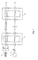
- the fixed lobe 2 is mounted in the body 1 by any known suitable means for the construction of bearings with fixed profiles (screws or studs). It is lubricated in upstream by a groove 4 in the traditional way.
- Each oscillating pad has a radius of curvature less than the radius of the surface of the body, so that it sits on that surface along a line around which it can swing freely. In the absence of the tree 6, it is held in place by a stop ring designated by 7-7 '. When the shaft is in place and reaches its nominal rotation speed, each shoe 3-3 ' tilt to take its optimal position, without any contact.
- each pad is located in the vicinity of the fixed lobe 2, and is constantly in circumferential abutment on pads 8-8 'downstream and on lubrication nozzles 9-9 'upstream.
- Figure 3 shows the distribution of each set of three nozzles, with directed jets 9a, 9b, 9c.
- the shaft 6 rotates in the direction ⁇ and the load is oriented in the direction of arrow F.
- a body 11 to which a fixed lobe 12, extending over approximately 115 ° of arc is fixed for example by screws or studs, and lubricated upstream by a groove 14 and a pair of oscillating pads 13-13 'extending over approximately 60 ° of arc near the ends of the lobe fixed, and in circumferential abutment on studs (not shown) downstream, and on nozzles lubrication 19-19 'upstream, with directed jets (see Figure 6).
- the pads 13-13 ' are mounted on the inside of the body by means of ball joints comprising a spherical cap 21, held on the body 11 by a screw 22, and cooperating with a corresponding spherical cavity-shaped housing in the back of the shoe 13-13 '.
- the shaft 6 rotates in the direction ⁇ and the load is applied in the direction of arrow F.
- the elements of the ball joint namely the axis of the cap 21 and the axis of the cavity of the shoe 13, are offset, so as to create an off-center pivot ensuring better bearing performance.
- the skids can tilt in the direction of rotation of the shaft, but moreover they can also tilt in the perpendicular direction, i.e. parallel to the axis of the bearing, to adapt to the possible bending of the shaft.
- the approximate total length of the bearing surfaces of the fixed lobe and two pads is about 235 ° of arc. If we attribute to the studs and nozzles ensuring the circumferential stop of the pads a total length about 50 ° of arc, there remains therefore, between said pads, a clear space representing approximately 65 ° of arc, on which no load is applied. We can at least partially attribute this performance to upper bearings according to the invention, as will be explained below by reference to experimental and theoretical studies.
- FIG. 7 illustrates the principle of the so-called "back to back” tests.
- the two devices used are identical by their train and their center distance.
- the arrows materialize the sides active teeth.
- the setting in motion of the assembly is obtained at by means of a motor M coupled to the shaft end of line 4 at low speed (P.V.), while the loading takes place by means of a device C in high speed shaft end (G.V.).
- the whole line of trees has an overall torsional stiffness constant, so that if at a coupling point on the tree line, we realizes a relative angular phase shift between the two plates coupling, this results in a load torque proportional to the phase shift.
- the nominal torque of devices will be reached for higher or lower phase shift values.
- the axial displacement of a mobile relative to the Conjugated toothing causes the desired relative rotation.
- This movement is obtained through the use of an oscillating shoe stop on which the axial loading forces are exerted via a jack self-locking high pressure hydraulic system C. These forces are equal and opposite axial reactions on the teeth corresponding to the transmitted load.
- the radial load applied to the bearings therefore results here from the axial force of the cylinder applied to the helical teeth of the testing machines.
- Temperature measurement is carried out using thermocouples mainly placed on the periphery of the pads, their sensitive part being directly implanted in the regulating layer and flush with the internal surface skates.
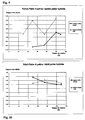
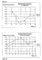
- Table II below brings together the ratios, expressed in%, between the values of the temperatures thus measured in the median plane of the bearing 11B of FIG. 7, respectively when this bearing is of the type with five oscillating pads with centered pivots and when this bearing is of the hybrid type according to the invention, for loads W% ranging from 0 (no-load operation) to 100 (nominal load) and for speeds N% ranging from 25% to 100% of the nominal speed (operating point normal), and even beyond 100% (overspeed in some applications).
- Figure 8 graphically illustrates the variation of this same ratio, under form of a curve for each load value, forming the speed of rotation.
- Table III combines the ratios, expressed in%, between the values, in kW, of the power dissipated by a bearing, respectively when this bearing is of the type with five oscillating pads with centered pivots and when this bearing is of hybrid type according to the invention, for combinations between the speed N (which can range from 25 to 100% and even beyond, the normal speed), and the load W (which can range from 0 to 100% of nominal load).
- This table III also brings together the ratios, in%, between the debits, measured at variable load, as a function of speed, for the two types of bearings.
Landscapes
- Engineering & Computer Science (AREA)
- General Engineering & Computer Science (AREA)
- Mechanical Engineering (AREA)
- Chemical & Material Sciences (AREA)
- Oil, Petroleum & Natural Gas (AREA)
- Physics & Mathematics (AREA)
- Fluid Mechanics (AREA)
- Sliding-Contact Bearings (AREA)
- Pivots And Pivotal Connections (AREA)
- Support Of The Bearing (AREA)
Claims (5)
- Hydrodynamisches Lager des Typs mit mehreren in bezug auf die innere Umfangsfläche des Körpers des Lagers oszillierend angebrachten Kufen,
mit einem in bezug auf die Umfangsfläche festen Bogenstück auf einem Bruchteil dieser Fläche und mit zwei oszillierenden Kufen in der Nähe jedes Endes dieses Bogenstücks, dadurch gekennzeichnet, daß diese beiden Kufen um eine Strecke getrennt sind, die im wesentlichen gleich der Bogenlänge einer Kufe ist, wobei jede Kufe so angebracht ist, daß sie auf einer Seite an einem stromabseitig befindlichen Anschlag und an der anderen an einer stromaufseitig befindlichen Schmierungsdüse anliegt. - Lager nach Anspruch 1, in dem jede Kufe längs einer zur Achse des Lagers parallelen Linie in tangentialem Kontakt mit der inneren Oberfläche ist, wobei die Kufe in einer einzigen Richtung um die Tangentiallinie oszillieren kann, um während der Drehung der vom Lager unterstützten Welle seine optimale Position einzunehmen.
- Lager nach Anspruch 1, in dem zwischen jede Kufe und die innere Oberfläche ein Knochengelenk eingesetzt ist, das durch eine sphärische Kappe gebildet ist, die auf der inneren Oberfläche befestigt ist und mit einem entsprechenden sphärischen Hohlraum der hinteren Fläche der Kufe zusammenwirkt, wobei die Kufe in allen Richtungen um das Gelenk oszillieren kann, um während der Drehung der vom Lager unterstützten Welle ihre optimale Position einzunehmen.
- Lager nach Anspruch 3, in dem die Achse des sphärischen Hohlraums in bezug auf die Achse der sphärischen Kappe versetzt ist.
- Lager nach irgendeinem der vorangehenden Ansprüche, in dem das feste Bogenstück einen Bogen von ungefähr 115° überspannt, wobei jede oszillierende Kufe, die sich beiderseits des festen Bogenstücks befindet, einen Bogen von ungefähr 60° überspannt und der freie Raum, der zwischen den beiden oszillierenden Kufen vorhanden ist, die übrigen 125° des Bogens bildet, wenn die Dicke der Kontakte und Schmierungsdüsen und das Spiel zwischen den beweglichen und festen Elementen vernachlässigt werden.
Priority Applications (3)
| Application Number | Priority Date | Filing Date | Title |
|---|---|---|---|
| EP96440015A EP0789151B1 (de) | 1996-02-06 | 1996-02-06 | Hydrodynamisches Lager mit einer festen Gleitfläche sowie kippbaren Gleitsegmenten |
| DE69608238T DE69608238T2 (de) | 1996-02-06 | 1996-02-06 | Hydrodynamisches Lager mit einer festen Gleitfläche sowie kippbaren Gleitsegmenten |
| AT96440015T ATE192830T1 (de) | 1996-02-06 | 1996-02-06 | Hydrodynamisches lager mit einer festen gleitfläche sowie kippbaren gleitsegmenten |
Applications Claiming Priority (1)
| Application Number | Priority Date | Filing Date | Title |
|---|---|---|---|
| EP96440015A EP0789151B1 (de) | 1996-02-06 | 1996-02-06 | Hydrodynamisches Lager mit einer festen Gleitfläche sowie kippbaren Gleitsegmenten |
Publications (2)
| Publication Number | Publication Date |
|---|---|
| EP0789151A1 EP0789151A1 (de) | 1997-08-13 |
| EP0789151B1 true EP0789151B1 (de) | 2000-05-10 |
Family
ID=8225403
Family Applications (1)
| Application Number | Title | Priority Date | Filing Date |
|---|---|---|---|
| EP96440015A Expired - Lifetime EP0789151B1 (de) | 1996-02-06 | 1996-02-06 | Hydrodynamisches Lager mit einer festen Gleitfläche sowie kippbaren Gleitsegmenten |
Country Status (3)
| Country | Link |
|---|---|
| EP (1) | EP0789151B1 (de) |
| AT (1) | ATE192830T1 (de) |
| DE (1) | DE69608238T2 (de) |
Families Citing this family (6)
| Publication number | Priority date | Publication date | Assignee | Title |
|---|---|---|---|---|
| JP3871950B2 (ja) * | 2002-03-28 | 2007-01-24 | 三菱電機株式会社 | ガイド軸受装置 |
| JP4764486B2 (ja) * | 2009-02-27 | 2011-09-07 | 三菱重工業株式会社 | ジャーナル軸受 |
| EP2669537A1 (de) * | 2012-06-01 | 2013-12-04 | Alstom Technology Ltd. | Radiales Segmentlager für Turbine |
| CN102966830A (zh) * | 2012-11-02 | 2013-03-13 | 三一能源重工有限公司 | 一种喷油嘴 |
| EP3263934A4 (de) * | 2015-03-31 | 2018-05-30 | Mitsubishi Heavy Industries Compressor Corporation | Tragevorrichtung und drehmaschine |
| CN114688157B (zh) * | 2020-12-25 | 2024-09-10 | 上海电气电站设备有限公司 | 一种用于汽轮机的液磁耦合轴承装置及汽轮机 |
Family Cites Families (2)
| Publication number | Priority date | Publication date | Assignee | Title |
|---|---|---|---|---|
| US4597676A (en) * | 1984-04-30 | 1986-07-01 | General Electric Company | Hybrid bearing |
| US4686403A (en) * | 1986-11-07 | 1987-08-11 | Westinghouse Electric Corp. | Dynamoelectric machine with rockable bearing supports |
-
1996
- 1996-02-06 EP EP96440015A patent/EP0789151B1/de not_active Expired - Lifetime
- 1996-02-06 AT AT96440015T patent/ATE192830T1/de not_active IP Right Cessation
- 1996-02-06 DE DE69608238T patent/DE69608238T2/de not_active Expired - Fee Related
Also Published As
| Publication number | Publication date |
|---|---|
| DE69608238D1 (de) | 2000-06-15 |
| EP0789151A1 (de) | 1997-08-13 |
| ATE192830T1 (de) | 2000-05-15 |
| DE69608238T2 (de) | 2001-02-08 |
Similar Documents
| Publication | Publication Date | Title |
|---|---|---|
| EP0399888B1 (de) | Kontinuierlich verstellbares automatisches mechanisches Getriebe mit einem Übersetzungsverhältnis von unendlich bis kleiner als eins | |
| FR2673685A1 (fr) | Compresseur du type rotatif pour climatisation ou refrigeration. | |
| FR2807125A1 (fr) | Joint universel homocinetique | |
| EP2935939B1 (de) | Vorrichtung zur absorption von vibrationen | |
| FR2823815A1 (fr) | Joint universel homocinetique | |
| EP0060822A1 (de) | Motor mit geradliniger Bewegung und Taumelscheibe dafür | |
| EP0789151B1 (de) | Hydrodynamisches Lager mit einer festen Gleitfläche sowie kippbaren Gleitsegmenten | |
| EP2935938B1 (de) | Schwingungsdämpfende vorrichtung | |
| FR2812916A1 (fr) | Joint universel homocinetique de type tripode | |
| EP1759125B1 (de) | Vorrichtung zur schaftführung bei oszillationsbewegungen | |
| EP0220094A1 (de) | Federungsaggregat mit Schwingenarm für Fahrzeuge | |
| FR2654782A1 (fr) | Joint de transmission articule telescopique, notamment pour l'automobile. | |
| FR2991739A1 (fr) | Dispositif d'amortissement pendulaire a element de roulement stabilise | |
| FR2578761A1 (fr) | Dispositif de paliers pour un arbre en rotation, notamment pour les arbres d'entrainement de cylindres de laminoirs | |
| EP3245427B1 (de) | Verfahren zur herstellung eines propelleruntersetzungsgetriebes | |
| FR2763658A1 (fr) | Embrayage centrifuge dont les masselottes portent des machoires cooperant par friction avec un tambour | |
| WO1997021047A1 (fr) | Double volant amortisseur a limiteur de couple annulaire | |
| FR2834011A1 (fr) | Moteur hydraulique a pistons radiaux | |
| EP0319354B1 (de) | Antriebsvorrichtung eines Zahnrades mittels eines selbstausrichtenden fliegenden Ritzels | |
| FR2990734A1 (fr) | Bossage pour systeme pendulaire d'amortissement | |
| FR2715444A1 (fr) | Perfectionnement aux dispositifs à patins glissants de machine, notamment de pompes et moteurs hydrauliques. | |
| WO2006103362A2 (fr) | Dispositif de transformation reversible d’un mouvement rectiligne alternatif en un mouvement de rotation, et machines associes | |
| FR2780128A1 (fr) | Poulie relais pour la transmission sans fin de puissance a vitesse variable | |
| FR3134605A1 (fr) | Palier de rotation entre un organe rotatif et un arbre de boite de vitesses | |
| FR2862118A1 (fr) | Dispositif pour le rattrapage des jeux de dents entre deux pignons et arbre d'entrainement comportant un tel dispositif |
Legal Events
| Date | Code | Title | Description |
|---|---|---|---|
| PUAI | Public reference made under article 153(3) epc to a published international application that has entered the european phase |
Free format text: ORIGINAL CODE: 0009012 |
|
| 17P | Request for examination filed |
Effective date: 19960227 |
|
| AK | Designated contracting states |
Kind code of ref document: A1 Designated state(s): AT BE CH DE DK ES FR GB GR IE IT LI LU MC NL PT SE |
|
| AX | Request for extension of the european patent |
Free format text: LT PAYMENT 960227;LV PAYMENT 960227;SI PAYMENT 960227 |
|
| GRAG | Despatch of communication of intention to grant |
Free format text: ORIGINAL CODE: EPIDOS AGRA |
|
| GRAG | Despatch of communication of intention to grant |
Free format text: ORIGINAL CODE: EPIDOS AGRA |
|
| GRAH | Despatch of communication of intention to grant a patent |
Free format text: ORIGINAL CODE: EPIDOS IGRA |
|
| RTI1 | Title (correction) |
Free format text: HYDRODYNAMIC BEARING COMPRISING A FIXED SLIDING SURFACE AND TILTABLE SLIDING PADS |
|
| 17Q | First examination report despatched |
Effective date: 19990903 |
|
| GRAH | Despatch of communication of intention to grant a patent |
Free format text: ORIGINAL CODE: EPIDOS IGRA |
|
| GRAA | (expected) grant |
Free format text: ORIGINAL CODE: 0009210 |
|
| RIN1 | Information on inventor provided before grant (corrected) |
Inventor name: WEBER, FRANCOIS |
|
| AK | Designated contracting states |
Kind code of ref document: B1 Designated state(s): AT BE CH DE DK ES FR GB GR IE IT LI LU MC NL PT SE |
|
| AX | Request for extension of the european patent |
Free format text: LT PAYMENT 19960227;LV PAYMENT 19960227;SI PAYMENT 19960227 |
|
| LTIE | Lt: invalidation of european patent or patent extension | ||
| PG25 | Lapsed in a contracting state [announced via postgrant information from national office to epo] |
Ref country code: ES Free format text: THE PATENT HAS BEEN ANNULLED BY A DECISION OF A NATIONAL AUTHORITY Effective date: 20000510 Ref country code: AT Free format text: LAPSE BECAUSE OF FAILURE TO SUBMIT A TRANSLATION OF THE DESCRIPTION OR TO PAY THE FEE WITHIN THE PRESCRIBED TIME-LIMIT Effective date: 20000510 |
|
| REF | Corresponds to: |
Ref document number: 192830 Country of ref document: AT Date of ref document: 20000515 Kind code of ref document: T |
|
| REG | Reference to a national code |
Ref country code: CH Ref legal event code: EP |
|
| REG | Reference to a national code |
Ref country code: IE Ref legal event code: FG4D Free format text: FRENCH |
|
| REF | Corresponds to: |
Ref document number: 69608238 Country of ref document: DE Date of ref document: 20000615 |
|
| ITF | It: translation for a ep patent filed | ||
| PG25 | Lapsed in a contracting state [announced via postgrant information from national office to epo] |
Ref country code: PT Free format text: LAPSE BECAUSE OF FAILURE TO SUBMIT A TRANSLATION OF THE DESCRIPTION OR TO PAY THE FEE WITHIN THE PRESCRIBED TIME-LIMIT Effective date: 20000810 Ref country code: DK Free format text: LAPSE BECAUSE OF FAILURE TO SUBMIT A TRANSLATION OF THE DESCRIPTION OR TO PAY THE FEE WITHIN THE PRESCRIBED TIME-LIMIT Effective date: 20000810 |
|
| PG25 | Lapsed in a contracting state [announced via postgrant information from national office to epo] |
Ref country code: GR Free format text: LAPSE BECAUSE OF FAILURE TO SUBMIT A TRANSLATION OF THE DESCRIPTION OR TO PAY THE FEE WITHIN THE PRESCRIBED TIME-LIMIT Effective date: 20000811 |
|
| GBT | Gb: translation of ep patent filed (gb section 77(6)(a)/1977) |
Effective date: 20000804 |
|
| PG25 | Lapsed in a contracting state [announced via postgrant information from national office to epo] |
Ref country code: LU Free format text: LAPSE BECAUSE OF NON-PAYMENT OF DUE FEES Effective date: 20010206 |
|
| PG25 | Lapsed in a contracting state [announced via postgrant information from national office to epo] |
Ref country code: MC Free format text: LAPSE BECAUSE OF NON-PAYMENT OF DUE FEES Effective date: 20010228 Ref country code: BE Free format text: LAPSE BECAUSE OF NON-PAYMENT OF DUE FEES Effective date: 20010228 |
|
| PG25 | Lapsed in a contracting state [announced via postgrant information from national office to epo] |
Ref country code: IE Free format text: LAPSE BECAUSE OF NON-PAYMENT OF DUE FEES Effective date: 20010309 |
|
| PLBE | No opposition filed within time limit |
Free format text: ORIGINAL CODE: 0009261 |
|
| STAA | Information on the status of an ep patent application or granted ep patent |
Free format text: STATUS: NO OPPOSITION FILED WITHIN TIME LIMIT |
|
| REG | Reference to a national code |
Ref country code: IE Ref legal event code: FD4D |
|
| 26N | No opposition filed | ||
| BERE | Be: lapsed |
Owner name: FLENDER GRAFFENSTADEN Effective date: 20010228 |
|
| REG | Reference to a national code |
Ref country code: GB Ref legal event code: IF02 |
|
| PGFP | Annual fee paid to national office [announced via postgrant information from national office to epo] |
Ref country code: SE Payment date: 20020218 Year of fee payment: 7 Ref country code: NL Payment date: 20020218 Year of fee payment: 7 |
|
| PGFP | Annual fee paid to national office [announced via postgrant information from national office to epo] |
Ref country code: GB Payment date: 20020219 Year of fee payment: 7 |
|
| PGFP | Annual fee paid to national office [announced via postgrant information from national office to epo] |
Ref country code: FR Payment date: 20020228 Year of fee payment: 7 |
|
| PGFP | Annual fee paid to national office [announced via postgrant information from national office to epo] |
Ref country code: DE Payment date: 20020304 Year of fee payment: 7 |
|
| PGFP | Annual fee paid to national office [announced via postgrant information from national office to epo] |
Ref country code: CH Payment date: 20020314 Year of fee payment: 7 |
|
| PG25 | Lapsed in a contracting state [announced via postgrant information from national office to epo] |
Ref country code: GB Free format text: LAPSE BECAUSE OF NON-PAYMENT OF DUE FEES Effective date: 20030206 |
|
| PG25 | Lapsed in a contracting state [announced via postgrant information from national office to epo] |
Ref country code: SE Free format text: LAPSE BECAUSE OF NON-PAYMENT OF DUE FEES Effective date: 20030207 |
|
| PG25 | Lapsed in a contracting state [announced via postgrant information from national office to epo] |
Ref country code: LI Free format text: LAPSE BECAUSE OF NON-PAYMENT OF DUE FEES Effective date: 20030228 Ref country code: CH Free format text: LAPSE BECAUSE OF NON-PAYMENT OF DUE FEES Effective date: 20030228 |
|
| PG25 | Lapsed in a contracting state [announced via postgrant information from national office to epo] |
Ref country code: NL Free format text: LAPSE BECAUSE OF NON-PAYMENT OF DUE FEES Effective date: 20030901 |
|
| PG25 | Lapsed in a contracting state [announced via postgrant information from national office to epo] |
Ref country code: DE Free format text: LAPSE BECAUSE OF NON-PAYMENT OF DUE FEES Effective date: 20030902 |
|
| GBPC | Gb: european patent ceased through non-payment of renewal fee | ||
| EUG | Se: european patent has lapsed | ||
| REG | Reference to a national code |
Ref country code: CH Ref legal event code: PL |
|
| PG25 | Lapsed in a contracting state [announced via postgrant information from national office to epo] |
Ref country code: FR Free format text: LAPSE BECAUSE OF NON-PAYMENT OF DUE FEES Effective date: 20031031 |
|
| NLV4 | Nl: lapsed or anulled due to non-payment of the annual fee |
Effective date: 20030901 |
|
| REG | Reference to a national code |
Ref country code: FR Ref legal event code: ST |
|
| PG25 | Lapsed in a contracting state [announced via postgrant information from national office to epo] |
Ref country code: IT Free format text: LAPSE BECAUSE OF NON-PAYMENT OF DUE FEES Effective date: 20050206 |