EP0789151A1 - Hydrodynamisches Lager mit einer befestigten Tragfläche und Kippsegmenten - Google Patents
Hydrodynamisches Lager mit einer befestigten Tragfläche und Kippsegmenten Download PDFInfo
- Publication number
- EP0789151A1 EP0789151A1 EP96440015A EP96440015A EP0789151A1 EP 0789151 A1 EP0789151 A1 EP 0789151A1 EP 96440015 A EP96440015 A EP 96440015A EP 96440015 A EP96440015 A EP 96440015A EP 0789151 A1 EP0789151 A1 EP 0789151A1
- Authority
- EP
- European Patent Office
- Prior art keywords
- bearing
- shoe
- pads
- oscillating
- lobe
- Prior art date
- Legal status (The legal status is an assumption and is not a legal conclusion. Google has not performed a legal analysis and makes no representation as to the accuracy of the status listed.)
- Granted
Links
Images


Classifications
-
- F—MECHANICAL ENGINEERING; LIGHTING; HEATING; WEAPONS; BLASTING
- F16—ENGINEERING ELEMENTS AND UNITS; GENERAL MEASURES FOR PRODUCING AND MAINTAINING EFFECTIVE FUNCTIONING OF MACHINES OR INSTALLATIONS; THERMAL INSULATION IN GENERAL
- F16C—SHAFTS; FLEXIBLE SHAFTS; ELEMENTS OR CRANKSHAFT MECHANISMS; ROTARY BODIES OTHER THAN GEARING ELEMENTS; BEARINGS
- F16C33/00—Parts of bearings; Special methods for making bearings or parts thereof
- F16C33/02—Parts of sliding-contact bearings
- F16C33/04—Brasses; Bushes; Linings
- F16C33/06—Sliding surface mainly made of metal
- F16C33/10—Construction relative to lubrication
- F16C33/1025—Construction relative to lubrication with liquid, e.g. oil, as lubricant
- F16C33/106—Details of distribution or circulation inside the bearings, e.g. details of the bearing surfaces to affect flow or pressure of the liquid
- F16C33/1075—Wedges, e.g. ramps or lobes, for generating pressure
-
- F—MECHANICAL ENGINEERING; LIGHTING; HEATING; WEAPONS; BLASTING
- F16—ENGINEERING ELEMENTS AND UNITS; GENERAL MEASURES FOR PRODUCING AND MAINTAINING EFFECTIVE FUNCTIONING OF MACHINES OR INSTALLATIONS; THERMAL INSULATION IN GENERAL
- F16C—SHAFTS; FLEXIBLE SHAFTS; ELEMENTS OR CRANKSHAFT MECHANISMS; ROTARY BODIES OTHER THAN GEARING ELEMENTS; BEARINGS
- F16C17/00—Sliding-contact bearings for exclusively rotary movement
- F16C17/02—Sliding-contact bearings for exclusively rotary movement for radial load only
- F16C17/03—Sliding-contact bearings for exclusively rotary movement for radial load only with tiltably-supported segments, e.g. Michell bearings
-
- F—MECHANICAL ENGINEERING; LIGHTING; HEATING; WEAPONS; BLASTING
- F16—ENGINEERING ELEMENTS AND UNITS; GENERAL MEASURES FOR PRODUCING AND MAINTAINING EFFECTIVE FUNCTIONING OF MACHINES OR INSTALLATIONS; THERMAL INSULATION IN GENERAL
- F16C—SHAFTS; FLEXIBLE SHAFTS; ELEMENTS OR CRANKSHAFT MECHANISMS; ROTARY BODIES OTHER THAN GEARING ELEMENTS; BEARINGS
- F16C17/00—Sliding-contact bearings for exclusively rotary movement
- F16C17/12—Sliding-contact bearings for exclusively rotary movement characterised by features not related to the direction of the load
- F16C17/24—Sliding-contact bearings for exclusively rotary movement characterised by features not related to the direction of the load with devices affected by abnormal or undesired positions, e.g. for preventing overheating, for safety
- F16C17/243—Sliding-contact bearings for exclusively rotary movement characterised by features not related to the direction of the load with devices affected by abnormal or undesired positions, e.g. for preventing overheating, for safety related to temperature and heat, e.g. for preventing overheating
-
- F—MECHANICAL ENGINEERING; LIGHTING; HEATING; WEAPONS; BLASTING
- F16—ENGINEERING ELEMENTS AND UNITS; GENERAL MEASURES FOR PRODUCING AND MAINTAINING EFFECTIVE FUNCTIONING OF MACHINES OR INSTALLATIONS; THERMAL INSULATION IN GENERAL
- F16C—SHAFTS; FLEXIBLE SHAFTS; ELEMENTS OR CRANKSHAFT MECHANISMS; ROTARY BODIES OTHER THAN GEARING ELEMENTS; BEARINGS
- F16C2233/00—Monitoring condition, e.g. temperature, load, vibration
-
- F—MECHANICAL ENGINEERING; LIGHTING; HEATING; WEAPONS; BLASTING
- F16—ENGINEERING ELEMENTS AND UNITS; GENERAL MEASURES FOR PRODUCING AND MAINTAINING EFFECTIVE FUNCTIONING OF MACHINES OR INSTALLATIONS; THERMAL INSULATION IN GENERAL
- F16C—SHAFTS; FLEXIBLE SHAFTS; ELEMENTS OR CRANKSHAFT MECHANISMS; ROTARY BODIES OTHER THAN GEARING ELEMENTS; BEARINGS
- F16C2300/00—Application independent of particular apparatuses
- F16C2300/10—Application independent of particular apparatuses related to size
- F16C2300/14—Large applications, e.g. bearings having an inner diameter exceeding 500 mm
Definitions
- the present invention relates generally to the bearings and bearings serving as supports for the rotary shafts, and more specifically relates to those of these bearings used with large shafts rotating at high speed, for example the shafts of gear mechanisms (multipliers and speed reducers) intended to drive and / or be driven by turbomachines.
- gear mechanisms multipliers and speed reducers
- bearings with fixed profiles are known, formed by two fixed lobes in a body and used essentially on a line of shafts at low speed. These lobes can be offset (“offset halves") relative to the axis of the bearing, the shaft itself taking its optimal position when it reaches its nominal rotation speed. In such a case, the load application surface is maximum, so that the loss of efficiency of the bearing as well as of the gear is also maximum.
- Such bearings with oscillating pads are currently considered to be the most suitable for a line of high-speed shafts (cf. "Calculation of the static and dynamic characteristics of a bearing with oscillating pads", Laboratory of Contact Mechanics, INSA, LYON , June 1983).
- the invention is based on the surprising experimental observation that even better results can be obtained with bearings whose support consists in an association of a fixed lobe on approximately half of the bearing periphery, and on the other half, of two oscillating pads separated from each other by a distance representing approximately the developed length of a pad, this distance not being occupied by any support element.
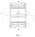
- the fixed lobe 2 is mounted in the body 1 by any suitable means known for the construction of bearings with fixed profiles (screws or studs). It is lubricated upstream by a groove 4 in the traditional way.
- Each oscillating pad has a radius of curvature less than the radius of the surface of the body, so that it sits on this surface along a line 5-5 'around which it can tilt freely. In the absence of the shaft 6, it is held in place by a stop ring designated by 7-7 '. When the shaft is in place and reaches its nominal rotation speed, each shoe 3-3 'swings to take its optimal position, without any contact.
- each shoe is located in the vicinity of the fixed lobe 2, and is constantly in circumferential abutment on pads 8-8 'downstream and on lubrication nozzles 9-9' upstream.
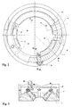
- Figure 3 shows the distribution of each set of three nozzles, directed jets 9a, 9b, 9c.
- the shaft 6 rotates in the direction ⁇ and the load is oriented in the direction of the arrow F.
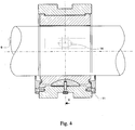
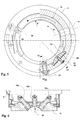
- a body 11 to which a fixed lobe 12, extending over approximately 115 ° of arc is fixed for example by screws or studs, and lubricated upstream by a groove 14 and a pair of oscillating pads 13-13 ′ extending over approximately 60 ° of arc in the vicinity of the ends of the lobe fixed, and in circumferential abutment on pots 18-18 'downstream, and on lubrication nozzles 19-19' upstream, with directed jets (see Figure 6).
- the skids 3-3 ' which are only free when tilting in the direction of rotation of the shaft
- the skids 13-13' are mounted on the inside of the body by means of articulations with ball joint comprising a spherical cap 21, held on the body 11 by a screw 22, and cooperating with a housing in the form of a corresponding spherical cavity in the rear face of the shoe 13-13 '.
- an adjustment piece 23 ensuring the accuracy of the height dimension of the shoe 13, which avoids having to machine it, and allows in same time to regulate the game.
- the shaft 6 rotates in the direction ⁇ and the load is applied in the direction of the arrow F.
- the elements of the ball joint namely the axis of the cap 21 and the axis of the spherical cavity of the shoe 13, are offset, so as to create a off-center pivot ensuring better bearing performance.
- the pads tilt in the direction of rotation of the shaft, but moreover they can also tilt in the perpendicular direction, that is to say parallel to the axis of the bearing, to adapt to possible bending of the shaft.
- the approximate total length of the bearing surfaces of the fixed lobe and of the two pads is approximately 235 ° of arc. If the pots and nozzles ensuring the circumferential stop of the pads are allocated a total length of approximately 50 ° of arc, there therefore remains, between said pads, a clear space representing approximately 65 ° of arc, on which n ' no charge is applied.
- This superiority can be attributed at least in part to the superior performance of the bearings according to the invention, as will be explained below with reference to experimental and theoretical studies.
- the aim of the tests was the comparative study of bearings with 5 oscillating pads, with pivots either centered or offset, and of a hybrid bearing with a fixed supporting lobe and two oscillating pads with stabilizing pivots.
- the entire shaft line has a constant overall torsional stiffness, so that if at a coupling point on the shaft line, a relative angular phase shift is achieved between the two coupling plates, it results a load torque proportional to the phase shift.
- the nominal torque of the devices will be reached for higher or lower phase shift values.
- the axial displacement of a mobile relative to the conjugate teeth causes the desired relative rotation.
- This movement is obtained through the use of a stop with oscillating pads on which the axial loading forces are exerted by means of a self-locking high pressure hydraulic cylinder C. These forces are equal and opposite to the axial reactions on the teeth corresponding to the transmitted load.
- the radial load applied to the bearings therefore results here from the axial force of the jack applied to the helical teeth of the test machines.
- the temperature measurement is carried out by means of thermocouples placed mainly on the periphery of the pads, their sensitive part being directly implanted in the regulating layer and flush with the internal surface of the pads.
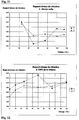
- Table II below brings together the ratios, expressed in%, between the values of the temperatures thus measured in the median plane of the bearing 11B of FIG. 7, respectively when this bearing is of the type with five oscillating pads with centered pivots and when this bearing is of the hybrid type according to the invention, for loads W% ranging from 0 (no-load operation) to 100 (nominal load) and for speeds N% ranging from 25% to 100% of the nominal speed (operating point normal), and even beyond 100% (overspeed in some applications).
- Temperature report (%) W% NOT(%) 0 10 25 50 75 100 25 0.97 50 1.03 1.10 1.17 1.20 1.22 75 0.99 1.06 1.15 1.14 1.15 100 1.03 1.00 1.09 1.14 1.17 110 1.05 1.16 1.16 1.22 115 1.05
- FIG. 8 graphically illustrates the variation of this same ratio, in the form of a curve for each load value, in formation of the speed of rotation.
- Table III brings together the ratios, expressed in%, between the values, in kW, of the power dissipated by a bearing, respectively when this bearing is of the type with five oscillating pads with centered pivots and when this bearing is of hybrid type according to the invention, for combinations between the speed N (which can range from 25 to 100% and even beyond, the normal speed), and the load W (which can range from 0 to 100% of nominal load).
- This table III also brings together the ratios, in%, between the flow rates, measured at variable load, as a function of the speed, for the two types of bearings.
- FIG. 11 graphically illustrates the variations in the ratio of the levels of vibration, vertical and horizontal, between the two types of bearings, at zero load, as a function of the speed.
- table V brings together the values, in%, of the ratio between the values of the amplitudes of vibration, respectively for the conventional bearing and the bearing according to the invention, at nominal speed (N at 100%) , depending on the load W.
- Ratio of vibration amplitudes (%) (Nominal speed and variable load) W% V H 0 1.73 1.42 10 1.92 1.70 25 2.06 1.88 50 2.33 1.83 75 1.78 1.87 100 2.02 2.08
Landscapes
- Engineering & Computer Science (AREA)
- General Engineering & Computer Science (AREA)
- Mechanical Engineering (AREA)
- Chemical & Material Sciences (AREA)
- Oil, Petroleum & Natural Gas (AREA)
- Physics & Mathematics (AREA)
- Fluid Mechanics (AREA)
- Sliding-Contact Bearings (AREA)
- Pivots And Pivotal Connections (AREA)
- Support Of The Bearing (AREA)
Priority Applications (3)
| Application Number | Priority Date | Filing Date | Title |
|---|---|---|---|
| EP96440015A EP0789151B1 (de) | 1996-02-06 | 1996-02-06 | Hydrodynamisches Lager mit einer festen Gleitfläche sowie kippbaren Gleitsegmenten |
| DE69608238T DE69608238T2 (de) | 1996-02-06 | 1996-02-06 | Hydrodynamisches Lager mit einer festen Gleitfläche sowie kippbaren Gleitsegmenten |
| AT96440015T ATE192830T1 (de) | 1996-02-06 | 1996-02-06 | Hydrodynamisches lager mit einer festen gleitfläche sowie kippbaren gleitsegmenten |
Applications Claiming Priority (1)
| Application Number | Priority Date | Filing Date | Title |
|---|---|---|---|
| EP96440015A EP0789151B1 (de) | 1996-02-06 | 1996-02-06 | Hydrodynamisches Lager mit einer festen Gleitfläche sowie kippbaren Gleitsegmenten |
Publications (2)
| Publication Number | Publication Date |
|---|---|
| EP0789151A1 true EP0789151A1 (de) | 1997-08-13 |
| EP0789151B1 EP0789151B1 (de) | 2000-05-10 |
Family
ID=8225403
Family Applications (1)
| Application Number | Title | Priority Date | Filing Date |
|---|---|---|---|
| EP96440015A Expired - Lifetime EP0789151B1 (de) | 1996-02-06 | 1996-02-06 | Hydrodynamisches Lager mit einer festen Gleitfläche sowie kippbaren Gleitsegmenten |
Country Status (3)
| Country | Link |
|---|---|
| EP (1) | EP0789151B1 (de) |
| AT (1) | ATE192830T1 (de) |
| DE (1) | DE69608238T2 (de) |
Cited By (5)
| Publication number | Priority date | Publication date | Assignee | Title |
|---|---|---|---|---|
| FR2837885A1 (fr) * | 2002-03-28 | 2003-10-03 | Mitsubishi Electric Corp | Dispositif de palier-guide |
| CN102149931A (zh) * | 2009-02-27 | 2011-08-10 | 三菱重工业株式会社 | 轴颈轴承 |
| CN102966830A (zh) * | 2012-11-02 | 2013-03-13 | 三一能源重工有限公司 | 一种喷油嘴 |
| US20130336605A1 (en) * | 2012-06-01 | 2013-12-19 | Alsom Technology Ltd | Journal bearing pad for turbine |
| CN114688157A (zh) * | 2020-12-25 | 2022-07-01 | 上海电气电站设备有限公司 | 一种用于汽轮机的液磁耦合轴承装置及汽轮机 |
Families Citing this family (1)
| Publication number | Priority date | Publication date | Assignee | Title |
|---|---|---|---|---|
| EP3263934A4 (de) * | 2015-03-31 | 2018-05-30 | Mitsubishi Heavy Industries Compressor Corporation | Tragevorrichtung und drehmaschine |
Citations (2)
| Publication number | Priority date | Publication date | Assignee | Title |
|---|---|---|---|---|
| US4597676A (en) * | 1984-04-30 | 1986-07-01 | General Electric Company | Hybrid bearing |
| US4686403A (en) * | 1986-11-07 | 1987-08-11 | Westinghouse Electric Corp. | Dynamoelectric machine with rockable bearing supports |
-
1996
- 1996-02-06 EP EP96440015A patent/EP0789151B1/de not_active Expired - Lifetime
- 1996-02-06 AT AT96440015T patent/ATE192830T1/de not_active IP Right Cessation
- 1996-02-06 DE DE69608238T patent/DE69608238T2/de not_active Expired - Fee Related
Patent Citations (2)
| Publication number | Priority date | Publication date | Assignee | Title |
|---|---|---|---|---|
| US4597676A (en) * | 1984-04-30 | 1986-07-01 | General Electric Company | Hybrid bearing |
| US4686403A (en) * | 1986-11-07 | 1987-08-11 | Westinghouse Electric Corp. | Dynamoelectric machine with rockable bearing supports |
Cited By (8)
| Publication number | Priority date | Publication date | Assignee | Title |
|---|---|---|---|---|
| FR2837885A1 (fr) * | 2002-03-28 | 2003-10-03 | Mitsubishi Electric Corp | Dispositif de palier-guide |
| CN102149931A (zh) * | 2009-02-27 | 2011-08-10 | 三菱重工业株式会社 | 轴颈轴承 |
| EP2402621A4 (de) * | 2009-02-27 | 2012-07-18 | Mitsubishi Heavy Ind Ltd | Achslager |
| CN102149931B (zh) * | 2009-02-27 | 2013-11-06 | 三菱重工业株式会社 | 轴颈轴承 |
| US20130336605A1 (en) * | 2012-06-01 | 2013-12-19 | Alsom Technology Ltd | Journal bearing pad for turbine |
| US9022658B2 (en) * | 2012-06-01 | 2015-05-05 | Alstom Technology Ltd | Journal bearing pad for turbine |
| CN102966830A (zh) * | 2012-11-02 | 2013-03-13 | 三一能源重工有限公司 | 一种喷油嘴 |
| CN114688157A (zh) * | 2020-12-25 | 2022-07-01 | 上海电气电站设备有限公司 | 一种用于汽轮机的液磁耦合轴承装置及汽轮机 |
Also Published As
| Publication number | Publication date |
|---|---|
| DE69608238D1 (de) | 2000-06-15 |
| EP0789151B1 (de) | 2000-05-10 |
| ATE192830T1 (de) | 2000-05-15 |
| DE69608238T2 (de) | 2001-02-08 |
Similar Documents
| Publication | Publication Date | Title |
|---|---|---|
| EP1799471B1 (de) | Fahrzeugbodenverbindung mit einem rad und einer darin integrierten aufhängung | |
| FR2673685A1 (fr) | Compresseur du type rotatif pour climatisation ou refrigeration. | |
| FR2829203A1 (fr) | Dispositif de blocage de stationnement d'un vehicule automobile | |
| FR2617552A1 (fr) | Joint homocinetique | |
| FR2831935A1 (fr) | Joint universel homocinetique comportant des moyens de suppression du basculement entre les tourillons et les galets | |
| EP2935939B1 (de) | Vorrichtung zur absorption von vibrationen | |
| EP2935938B1 (de) | Schwingungsdämpfende vorrichtung | |
| FR2576647A1 (fr) | Palier, notamment pour arbre tournant | |
| EP0789151B1 (de) | Hydrodynamisches Lager mit einer festen Gleitfläche sowie kippbaren Gleitsegmenten | |
| FR2812916A1 (fr) | Joint universel homocinetique de type tripode | |
| EP1759125B1 (de) | Vorrichtung zur schaftführung bei oszillationsbewegungen | |
| EP0491613B1 (de) | Handhabungsgerät zum Bewegen eines Gegenstandes in Raum, z.B. parallel mit sichselbst | |
| FR2654782A1 (fr) | Joint de transmission articule telescopique, notamment pour l'automobile. | |
| FR2578761A1 (fr) | Dispositif de paliers pour un arbre en rotation, notamment pour les arbres d'entrainement de cylindres de laminoirs | |
| EP0426540A1 (de) | Brennkraftmaschine mit variablem Hub | |
| FR2763658A1 (fr) | Embrayage centrifuge dont les masselottes portent des machoires cooperant par friction avec un tambour | |
| WO2016113494A1 (fr) | Procédé de fabrication d'un réducteur d'hélice | |
| FR2489907A1 (fr) | Dispositif d'accouplement pour joindre deux organes rotatifs | |
| EP3385573B1 (de) | Rollenwalzen für den drehantrieb eines luftfahrzeugrads | |
| FR2834011A1 (fr) | Moteur hydraulique a pistons radiaux | |
| EP0319354B1 (de) | Antriebsvorrichtung eines Zahnrades mittels eines selbstausrichtenden fliegenden Ritzels | |
| FR2507437A1 (fr) | Dispositif de stabilisation d'une poutre a suspension barycentrique et, en particulier, d'une rampe de pulverisation ainsi suspendue dans des appareils de protection des plantes | |
| FR2990734A1 (fr) | Bossage pour systeme pendulaire d'amortissement | |
| FR2581142A1 (fr) | Joint homocinetique, notamment pour transmission de vehicule. | |
| FR2715444A1 (fr) | Perfectionnement aux dispositifs à patins glissants de machine, notamment de pompes et moteurs hydrauliques. |
Legal Events
| Date | Code | Title | Description |
|---|---|---|---|
| PUAI | Public reference made under article 153(3) epc to a published international application that has entered the european phase |
Free format text: ORIGINAL CODE: 0009012 |
|
| 17P | Request for examination filed |
Effective date: 19960227 |
|
| AK | Designated contracting states |
Kind code of ref document: A1 Designated state(s): AT BE CH DE DK ES FR GB GR IE IT LI LU MC NL PT SE |
|
| AX | Request for extension of the european patent |
Free format text: LT PAYMENT 960227;LV PAYMENT 960227;SI PAYMENT 960227 |
|
| GRAG | Despatch of communication of intention to grant |
Free format text: ORIGINAL CODE: EPIDOS AGRA |
|
| GRAG | Despatch of communication of intention to grant |
Free format text: ORIGINAL CODE: EPIDOS AGRA |
|
| GRAH | Despatch of communication of intention to grant a patent |
Free format text: ORIGINAL CODE: EPIDOS IGRA |
|
| RTI1 | Title (correction) |
Free format text: HYDRODYNAMIC BEARING COMPRISING A FIXED SLIDING SURFACE AND TILTABLE SLIDING PADS |
|
| 17Q | First examination report despatched |
Effective date: 19990903 |
|
| GRAH | Despatch of communication of intention to grant a patent |
Free format text: ORIGINAL CODE: EPIDOS IGRA |
|
| GRAA | (expected) grant |
Free format text: ORIGINAL CODE: 0009210 |
|
| RIN1 | Information on inventor provided before grant (corrected) |
Inventor name: WEBER, FRANCOIS |
|
| AK | Designated contracting states |
Kind code of ref document: B1 Designated state(s): AT BE CH DE DK ES FR GB GR IE IT LI LU MC NL PT SE |
|
| AX | Request for extension of the european patent |
Free format text: LT PAYMENT 19960227;LV PAYMENT 19960227;SI PAYMENT 19960227 |
|
| LTIE | Lt: invalidation of european patent or patent extension | ||
| PG25 | Lapsed in a contracting state [announced via postgrant information from national office to epo] |
Ref country code: ES Free format text: THE PATENT HAS BEEN ANNULLED BY A DECISION OF A NATIONAL AUTHORITY Effective date: 20000510 Ref country code: AT Free format text: LAPSE BECAUSE OF FAILURE TO SUBMIT A TRANSLATION OF THE DESCRIPTION OR TO PAY THE FEE WITHIN THE PRESCRIBED TIME-LIMIT Effective date: 20000510 |
|
| REF | Corresponds to: |
Ref document number: 192830 Country of ref document: AT Date of ref document: 20000515 Kind code of ref document: T |
|
| REG | Reference to a national code |
Ref country code: CH Ref legal event code: EP |
|
| REG | Reference to a national code |
Ref country code: IE Ref legal event code: FG4D Free format text: FRENCH |
|
| REF | Corresponds to: |
Ref document number: 69608238 Country of ref document: DE Date of ref document: 20000615 |
|
| ITF | It: translation for a ep patent filed | ||
| PG25 | Lapsed in a contracting state [announced via postgrant information from national office to epo] |
Ref country code: PT Free format text: LAPSE BECAUSE OF FAILURE TO SUBMIT A TRANSLATION OF THE DESCRIPTION OR TO PAY THE FEE WITHIN THE PRESCRIBED TIME-LIMIT Effective date: 20000810 Ref country code: DK Free format text: LAPSE BECAUSE OF FAILURE TO SUBMIT A TRANSLATION OF THE DESCRIPTION OR TO PAY THE FEE WITHIN THE PRESCRIBED TIME-LIMIT Effective date: 20000810 |
|
| PG25 | Lapsed in a contracting state [announced via postgrant information from national office to epo] |
Ref country code: GR Free format text: LAPSE BECAUSE OF FAILURE TO SUBMIT A TRANSLATION OF THE DESCRIPTION OR TO PAY THE FEE WITHIN THE PRESCRIBED TIME-LIMIT Effective date: 20000811 |
|
| GBT | Gb: translation of ep patent filed (gb section 77(6)(a)/1977) |
Effective date: 20000804 |
|
| PG25 | Lapsed in a contracting state [announced via postgrant information from national office to epo] |
Ref country code: LU Free format text: LAPSE BECAUSE OF NON-PAYMENT OF DUE FEES Effective date: 20010206 |
|
| PG25 | Lapsed in a contracting state [announced via postgrant information from national office to epo] |
Ref country code: MC Free format text: LAPSE BECAUSE OF NON-PAYMENT OF DUE FEES Effective date: 20010228 Ref country code: BE Free format text: LAPSE BECAUSE OF NON-PAYMENT OF DUE FEES Effective date: 20010228 |
|
| PG25 | Lapsed in a contracting state [announced via postgrant information from national office to epo] |
Ref country code: IE Free format text: LAPSE BECAUSE OF NON-PAYMENT OF DUE FEES Effective date: 20010309 |
|
| PLBE | No opposition filed within time limit |
Free format text: ORIGINAL CODE: 0009261 |
|
| STAA | Information on the status of an ep patent application or granted ep patent |
Free format text: STATUS: NO OPPOSITION FILED WITHIN TIME LIMIT |
|
| REG | Reference to a national code |
Ref country code: IE Ref legal event code: FD4D |
|
| 26N | No opposition filed | ||
| BERE | Be: lapsed |
Owner name: FLENDER GRAFFENSTADEN Effective date: 20010228 |
|
| REG | Reference to a national code |
Ref country code: GB Ref legal event code: IF02 |
|
| PGFP | Annual fee paid to national office [announced via postgrant information from national office to epo] |
Ref country code: SE Payment date: 20020218 Year of fee payment: 7 Ref country code: NL Payment date: 20020218 Year of fee payment: 7 |
|
| PGFP | Annual fee paid to national office [announced via postgrant information from national office to epo] |
Ref country code: GB Payment date: 20020219 Year of fee payment: 7 |
|
| PGFP | Annual fee paid to national office [announced via postgrant information from national office to epo] |
Ref country code: FR Payment date: 20020228 Year of fee payment: 7 |
|
| PGFP | Annual fee paid to national office [announced via postgrant information from national office to epo] |
Ref country code: DE Payment date: 20020304 Year of fee payment: 7 |
|
| PGFP | Annual fee paid to national office [announced via postgrant information from national office to epo] |
Ref country code: CH Payment date: 20020314 Year of fee payment: 7 |
|
| PG25 | Lapsed in a contracting state [announced via postgrant information from national office to epo] |
Ref country code: GB Free format text: LAPSE BECAUSE OF NON-PAYMENT OF DUE FEES Effective date: 20030206 |
|
| PG25 | Lapsed in a contracting state [announced via postgrant information from national office to epo] |
Ref country code: SE Free format text: LAPSE BECAUSE OF NON-PAYMENT OF DUE FEES Effective date: 20030207 |
|
| PG25 | Lapsed in a contracting state [announced via postgrant information from national office to epo] |
Ref country code: LI Free format text: LAPSE BECAUSE OF NON-PAYMENT OF DUE FEES Effective date: 20030228 Ref country code: CH Free format text: LAPSE BECAUSE OF NON-PAYMENT OF DUE FEES Effective date: 20030228 |
|
| PG25 | Lapsed in a contracting state [announced via postgrant information from national office to epo] |
Ref country code: NL Free format text: LAPSE BECAUSE OF NON-PAYMENT OF DUE FEES Effective date: 20030901 |
|
| PG25 | Lapsed in a contracting state [announced via postgrant information from national office to epo] |
Ref country code: DE Free format text: LAPSE BECAUSE OF NON-PAYMENT OF DUE FEES Effective date: 20030902 |
|
| GBPC | Gb: european patent ceased through non-payment of renewal fee | ||
| EUG | Se: european patent has lapsed | ||
| REG | Reference to a national code |
Ref country code: CH Ref legal event code: PL |
|
| PG25 | Lapsed in a contracting state [announced via postgrant information from national office to epo] |
Ref country code: FR Free format text: LAPSE BECAUSE OF NON-PAYMENT OF DUE FEES Effective date: 20031031 |
|
| NLV4 | Nl: lapsed or anulled due to non-payment of the annual fee |
Effective date: 20030901 |
|
| REG | Reference to a national code |
Ref country code: FR Ref legal event code: ST |
|
| PG25 | Lapsed in a contracting state [announced via postgrant information from national office to epo] |
Ref country code: IT Free format text: LAPSE BECAUSE OF NON-PAYMENT OF DUE FEES Effective date: 20050206 |