EP0788965A2 - Electric power steering apparatus - Google Patents
Electric power steering apparatus Download PDFInfo
- Publication number
- EP0788965A2 EP0788965A2 EP96401875A EP96401875A EP0788965A2 EP 0788965 A2 EP0788965 A2 EP 0788965A2 EP 96401875 A EP96401875 A EP 96401875A EP 96401875 A EP96401875 A EP 96401875A EP 0788965 A2 EP0788965 A2 EP 0788965A2
- Authority
- EP
- European Patent Office
- Prior art keywords
- circuit
- signal
- gain
- target value
- lower limit
- Prior art date
- Legal status (The legal status is an assumption and is not a legal conclusion. Google has not performed a legal analysis and makes no representation as to the accuracy of the status listed.)
- Granted
Links
Images


Classifications
-
- B—PERFORMING OPERATIONS; TRANSPORTING
- B62—LAND VEHICLES FOR TRAVELLING OTHERWISE THAN ON RAILS
- B62D—MOTOR VEHICLES; TRAILERS
- B62D5/00—Power-assisted or power-driven steering
- B62D5/04—Power-assisted or power-driven steering electrical, e.g. using an electric servo-motor connected to, or forming part of, the steering gear
- B62D5/0457—Power-assisted or power-driven steering electrical, e.g. using an electric servo-motor connected to, or forming part of, the steering gear characterised by control features of the drive means as such
- B62D5/0481—Power-assisted or power-driven steering electrical, e.g. using an electric servo-motor connected to, or forming part of, the steering gear characterised by control features of the drive means as such monitoring the steering system, e.g. failures
- B62D5/0487—Power-assisted or power-driven steering electrical, e.g. using an electric servo-motor connected to, or forming part of, the steering gear characterised by control features of the drive means as such monitoring the steering system, e.g. failures detecting motor faults
-
- B—PERFORMING OPERATIONS; TRANSPORTING
- B62—LAND VEHICLES FOR TRAVELLING OTHERWISE THAN ON RAILS
- B62D—MOTOR VEHICLES; TRAILERS
- B62D5/00—Power-assisted or power-driven steering
- B62D5/04—Power-assisted or power-driven steering electrical, e.g. using an electric servo-motor connected to, or forming part of, the steering gear
- B62D5/0457—Power-assisted or power-driven steering electrical, e.g. using an electric servo-motor connected to, or forming part of, the steering gear characterised by control features of the drive means as such
- B62D5/046—Controlling the motor
- B62D5/0463—Controlling the motor calculating assisting torque from the motor based on driver input
Abstract
Description
- The invention relates to an improvement of an electric power steering apparatus.
- In a conventional electric power steering apparatus, a steering force assisting motor is controlled to be driven on the basis of a current target value of the steering force assisting motor which is determined on the basis of a steering torque, and a driving current of the steering force assisting motor. A control unit in which quick response performance is required is constructed by a microcomputer.
- In this conventional electric power steering apparatus, characteristics of the current target value of the steering force assisting motor to the steering torque are stored in a ROM in the structure of a data table, and the microcomputer calculates the current target value of the steering force assisting motor. Also, the microcomputer performs a process to obtain a difference of a value of the actually flowing current from the current target value of the steering force assisting motor for the purpose of feedback control.
- When the above-mentioned process is conducted with poor responsivity one feels unsatisfied at the steering. Hence, the microcomputer used is expensive to meet the necessity for high performance (high speed) in order to be resistive for use in processes required to be responded quickly. This increases production costs.
- A limiter circuit employing an analog circuit is used to prevent the current from flowing too much for the purpose of protecting the steering force assisting motor. A limit value of the current is fixed, and cannot be changed in accordance with running conditions of a vehicle such as a vehicle speed or a state when the vehicle stops.
- The invention has been devised in order to solve the above-mentioned problems. It is an object of the invention to provide an electric power steering apparatus which can furthermore improve the feeling a smoothness at the steerage while reducing production costs.
- An electric power steering apparatus according to the invention comprises a broken-line function circuit for outputting a predetermined analog broken-line function signal on the basis of a torque detection signal from a torque sensor for detecting a steering torque, a gain circuit for supplying a predetermined gain to the broken-line function signal, a polarity inverting circuit for inverting the polarity of the broken-line function signal, a first attenuating means for attenuating the torque detection signal at a predetermined rate, a second attenuating means for attenuating an output signal from the polarity inverting circuit at a predetermined rate, an addition circuit for adding a signal from the first attenuating means, an output signal of the gain circuit and an output signal of the second attenuating means and outputting the addition value as a target value of a motor current, a differential amplifying circuit for obtaining a difference between the motor current outputted from a circuit detecting the motor current and the target value for the purpose of feedback control, wherein a steering force assisting motor is driven on the basis of an output signal from the differential amplifying circuit.
- The broken-line function signal outputted from the broken-line function circuit is a main factor for synthesizing predetermined characteristics between the steering torque and the current target value of the steering force assisting motor. The signal obtained and outputted from the polarity inverting circuit by inverting the polarity of the broken-line function signal is a factor for changing the inclination of the above-mentioned broken-line function signal which is given the predetermined gain.
- The addition circuit outputs the addition value as the motor current target value based on the characteristics between the steering torque and the current target value of the steering force assisting motor shown in FIG. 1. Here, the signal outputted by the first attenuating means is a factor for giving the inclination of an "a" region where the steering torque is nearly 0 in the predetermined characteristics between the steering torque and the current target value of the steering force assisting motor.
- Consequently, in the electric power steering apparatus, a quick response is obtained. Also, the steering smoothness is improved and the resolution of the torque detection signal is enhanced thereby decreasing control noises. Further, an inexpensive microcomputer is utilizable thereby to decrease production costs.
- In the prior art, the lowest gain of a "b" region where the steering torque is large in both clockwise and counter-clockwise directions is equal to the gain of the "a" region where the steering torque is nearly 0 in the characteristics between the steering torque and the current target value of the steering force assisting motor, so that the characteristics obtained are in a narrow range. However, providing the polarity inverting circuit for calculating the target value allows the gain of the "b" region to be changed freely, whereby the characteristics range obtained is extended. Accordingly, the electric power steering apparatus is more widely applicable to kinds of vehicles.
- Also, the electric power steering apparatus further comprises a differential circuit for differentiating the torque detection signal and outputting the result to the polarity inverting circuit, wherein the addition circuit attenuates the output signal of the polarity inverting circuit at a predetermined rate, adds the attenuated signal, the output signal of the attenuating means and the output signal of the gain circuit, and outputs the addition value as the target value.
- In the electric power steering apparatus, phase compensation is performed by using the signal differentiated by the differential circuit for calculation of the target value. This improves response delay and makes inertial control for negating a weight load of the motor stable to suppress vibrations of a steering wheel.
- The electric power steering apparatus further comprises a gain determining means for determining the gain on the basis of the running condition of the vehicle, wherein the gain circuit supplies the gain determined by the gain determining means to the broken-line function signal.
- In this electric power steering apparatus, the gain determining means in the microcomputer determines the gain on the basis of the running condition of the vehicle such as running vehicle speed or stopping state, etc. Moreover, the process which has been handled by the microcomputer in the prior art is performed by the gain circuit of an analog circuit. This can lighten the burden of the microcomputer. When the resistance ratio of divided resistances for determining the gain in the gain circuit is 1:2:4:8, for example, a vehicle-speed characteristic (gain) of the electric power steering apparatus can be realized with an equal width.
- Also, it is another object of the invention to provide an electric power steering apparatus in which a limit value of a limiter circuit can be changed in correspondence with the running condition of a vehicle.
- In an electric power steering apparatus of the invention, upper/lower limit values which have been fixed values in the prior art are determined on the basis of the running condition of the vehicle such as running speed and stopping state, etc. by an upper/lower limit value determining means in a microcomputer, and a limiter circuit limits a motor current target value by the upper/lower limit values. In this way, the limit value of the limiter circuit which has been fixed in the prior art can be changed.
- The above and further objects and features of the invention will more fully be apparent from the following detailed description with accompanying drawings.
-
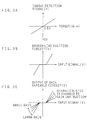
- FIG. 1 is a characteristic diagram of a steering torque and a current target value of a steering force assisting motor;
- FIG. 2 is a schematic block diagram showing a structure of an electric power steering apparatus of the invention;
- FIG. 3A is a characteristic diagram of a torque detection signal;
- FIG. 3B is a characteristic diagram of an output signal of a broken-line function circuit;
- FIG. 3C is a characteristic diagram of an output signal of a gain variable circuit;
- FIG. 4A is a characteristic diagram of an output signal of a polarity inverting circuit;
- FIG. 4B is a characteristic diagram of a motor target current signal;
- FIG. 5 is a circuit diagram showing an example of the broken-line function circuit, a phase compensating circuit, the polarity inverting circuit, the gain variable circuit, an addition circuit and a limiter circuit;
- FIG. 6 is a circuit diagram showing another example of the limiter circuit; and
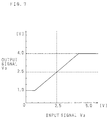
- FIG. 7 is a characteristic diagram of the limiter circuit of FIG. 6.
- Hereinafter, the invention will be described in detail with reference to the drawings showing its embodiments.
- FIG. 2 is a schematic block diagram showing an example of the structure of an electric power steering apparatus of the invention. In this electric power steering apparatus, a torque detection signal outputted from a
torque sensor 1 for detecting a steering torque disposed at a steering shaft is inputted to a broken-line function circuit 2, a phase compensating circuit (differential circuit) 3, amicrocomputer 22, and a phase compensating circuit (differential circuit) 11 and inputted also to anaddition circuit 7 via a resistance (first attenuating means) 6. - A broken-line function signal outputted from the broken-
line function circuit 2 is supplied to a gain variable circuit (gain circuit) 5 and a polarity invertingcircuit 4, and to the polarity invertingcircuit 4 is also supplied a differentiated signal of the torque detection signal outputted from thephase compensating circuit 3. - Further, the torque detection signal is differentiated and inverted in polarity by the
phase compensating circuit 3, then inverted again in polarity by the polarity invertingcircuit 4, to be returned to the original polarity. The gainvariable circuit 5 sets a gain on the basis of an instruction from again determining unit 20 of themicrocomputer 22, amplifies the broken-line function signal in accordance with the gain, and outputs the obtained signal to theaddition circuit 7. - The polarity inverting
circuit 4 adds the broken-line function signal and the differentiated signal of the torque detection signal, inverts the added signal in polarity, and supplies the obtained signal to a resistance (second attenuating means) 76. Theresistance 76 attenuates an output signal from the polarity invertingcircuit 4 at a predetermined rate and supplies the attenuated signal to theaddition circuit 7. Theaddition circuit 7 adds the signal attenuated by theresistance 76, the torque detection signal attenuated at a predetermined rate by theresistance 6 and an output signal of the gainvariable circuit 5, and outputs the obtained signal to alimiter circuit 8 as a current target value for a steeringforce assisting motor 24. Thelimiter circuit 8 sets upper/lower limit values of the current target value of themotor 24, limits the current target value of themotor 24 by the upper/lower limit values, and outputs the value to a differential amplifyingcircuit 9. - The
differential amplifying circuit 9 outputs a signal corresponding to a difference of a motor current value detected by a motor current detecting circuit 26 from the current target value of themotor 24 to amotor driving circuit 23. Themotor driving circuit 23 drives themotor 24 with PWM (pulse wave modulation) according to the signal from thedifferential amplifying circuit 9. The motor current detecting circuit 26 detects the motor current from a both ends voltage of aresistance 25 connected between themotor driving circuit 23 and a ground terminal and outputs the motor current detection signal to thedifferential amplifying circuit 9. - Still further, the torque detection signal from the
torque sensor 1 inputted to themicrocomputer 22 is converted to a digital signal by an A/D converter 10 and then given to a motor current targetvalue determining unit 12. The motor current targetvalue determining unit 12 determines the motor current target value on the basis of a data table storing characteristics between steering torques and motor current target values for every gain and an instruction value from thegain determining unit 20, and supplies the value to anaddition unit 13. - Moreover, the torque detection signal from the
torque sensor 1 is differentiated and inverted in polarity by thephase compensating circuit 11, and then converted to a digital signal by an A/D converter 27. After that, the digital signal is inverted in polarity by apolarity inverting unit 28 and supplied to theaddition unit 13. Theaddition unit 13 adds the signal from the motor current targetvalue determining unit 12 to the signal from thepolarity inverting unit 28 and outputs the result to a comparingunit 14. When the current target value of themotor 24 converted to a digital signal by an A/D converter 15 is supplied from theaddition circuit 7 to the comparingunit 14, the comparingunit 14 compares the current target value with the current target value from theaddition unit 13 and supplies the result of comparison to anabnormality judging unit 21. Theabnormality judging unit 21 judges the presence or absence of abnormality from the result. When theabnormality judging unit 21 judges that there is an abnormality, a diagnosis indication lamp is switched on. - A vehicle-speed signal is given from a vehicle-
speed sensor 16 to themicrocomputer 22. The vehicle-speed is converted to a digital signal by a vehicle-speed calculation unit 17 and then supplied to thegain determining unit 20 and an upper/lower limitvalue determining unit 18. Thegain determining unit 20 determines a gain of the gainvariable circuit 5 and a characteristic of the motor current targetvalue determining unit 12 based on the vehicle-speed signal, and the determined gain of a 4-bit digital signal is fed to the gainvariable circuit 5 and the motor current targetvalue determining unit 12. The upper/lower limitvalue determining unit 18 determines upper/lower limit values of thelimiter circuit 8, and instructs to thelimiter circuit 8 the determined upper/lower limit values via a D/A converter 19. - Hereinafter, the operation of the electric power steering apparatus having the above-mentioned configuration will be described.
- The torque detection signal from the
torque sensor 1 as shown in FIG. 3A is supplied to the broken-line function circuit 2, thephase compensating circuit 3, themicrocomputer 22 and thephase compensating circuit 11, and supplied to theaddition circuit 7 via theresistance 6. - The broken-line function signal outputted from the broken-
line function circuit 2 has a characteristic in the shape of a broken-line as shown in FIG. 3B, and it is applied to the gainvariable circuit 5 and thepolarity inverting circuit 4. To thepolarity inverting circuit 4 is supplied the differentiated signal of the torque detection signal outputted from thephase compensating circuit 3. The gainvariable circuit 5 sets the gain on the basis of the instruction of thegain determining unit 20, amplifies the broken-line function signal with the gain, and outputs the result to theaddition circuit 7. The output signal of the gainvariable circuit 5 can be changed in characteristic by varying the gain, as shown in FIG. 3C. - The
polarity inverting circuit 4 adds the broken-line function signal to the differentiated signal of the torque detection signal, inverts the added signal in polarity, and supplies the obtained polarity inverted signal as shown in FIG. 4A to theresistance 76. Theresistance 76 attenuates the output signal of thepolarity inverting circuit 4 at the predetermined rate and supplies the attenuated signal to theaddition circuit 7. Theaddition circuit 7 adds the signal attenuated by theresistance 76, the torque detection signal attenuated at the predetermined rate by theresistance 6 and the output signal of the gainvariable circuit 5, and outputs the added signal shown in FIG. 4B as the current target value of themotor 24. In the characteristic of the current target value shown in FIG. 4B, the inclination of a center region is determined by the value of theresistance 6. Since the attenuated signal of the output signal from thepolarity inverting circuit 4 is added, the characteristic can be changed more freely. - The current target value of the
motor 24 outputted from theaddition circuit 7 is inputted to thelimiter circuit 8. Thelimiter circuit 8 sets the upper/lower limit values of the current target value of themotor 24 on the basis of the instruction from the upper/lower limitvalue determining unit 18, limits the current target value of themotor 24 by the upper/lower limit values, and outputs the value to thedifferential amplifying circuit 9. The upper/lower limit values have the same width via a predetermined reference voltage as a center value. - The
differential amplifying circuit 9 outputs the signal corresponding to the difference between the current target value of themotor 24 and the motor current from the motor current detecting circuit 26 to themotor driving circuit 23. Themotor driving circuit 23 drives themotor 24 with PWM in accordance with the signal from thedifferential amplifying circuit 9. The motor current detecting circuit 26 detects the motor current from the both ends voltage of theresistance 25 to which the same current as that in themotor 24 flows, and outputs the detection signal of the motor current to thedifferential amplifying circuit 9. - Since the operation of the
microcomputer 22 is the same as the operation described in the above-mentioned arrangement, the description thereof will be omitted. - FIG. 5 is a circuit diagram showing an example of the broken-
line function circuit 2, thephase compensating circuit 3, thepolarity inverting circuit 4, the gainvariable circuit 5, theaddition circuit 7 and thelimiter circuit 8. - In the broken-
line function circuit 2, the torque detection signal from thetorque sensor 1 is inputted to inverting input terminals of OP-amps - A constant voltage of 2. 5V is applied to a non-inverting input terminal of the OP-
amp 46 via aresistance 48, and an output terminal of the OP-amp 46 is connected to an anode of adiode 49. A cathode of thediode 49 is connected to an inverting input terminal of the OP-amp 46 via aresistance 43. Theresistances 47 and 43 are set to have the same value. An anode of a diode 44 is connected to the inverting input terminal of the OP-amp 46. The diode 44 is forward-connected to adiode 45 whose cathode is connected to the output terminal of the OP-amp 46. A divided voltage of a voltage dividing circuit of a constant voltage of 5V comprising resistances 40 and 41 is applied to the inverting input terminal via aresistance 42. - A constant voltage of 2. 5V is applied to a non-inverting input terminal of the OP-
amp 56 via aresistance 58, and an output terminal of the OP-amp 56 is connected to a cathode of adiode 59 whose anode is connected to an inverting input terminal of the OP-amp 56 via a resistance 53. The resistances 57 and 53 are set to have the same value. A cathode of a diode 54 is connected to the inverting input terminal of the OP-amp 56. The diode 54 is forward-connected to adiode 55 whose anode is connected to the output terminal of the OP-amp 56. A divided voltage of a voltage dividing circuit of a constant voltage of 5V comprising resistances 50 and 51 is applied to the inverting input terminal via aresistance 52. - The two circuits essentially comprising the above-mentioned OP-
amps - Outputs of these ideal diodes are added via
resistances amp 64 via aresistance 63. - A constant voltage of 2.5V is applied to a non-inverting input terminal of the OP-
amp 64, and an output terminal of the OP-amp 64 is connected to the inverting input terminal thereof via aresistance 62 and theresistance 63. The circuit essentially constituted of the OP-amp 64 is an inverting amplifying circuit having an inversion voltage of 2.5V. - In the broken-
line function circuit 2, in the case where the divided voltages of the voltage dividing circuits (40 and 41 / 50 and 51) are respectively 2.8V and 2.2V, the OP-amp 46 outputs a negative voltage when the torque detection signal is 2.2 to 2.8V, because the voltage of the inverting input terminal of the OP-amp 46 shows a predominant tendency to be increased to be higher than the voltage of 2.5V due to the virtual short by the divided voltage of 2.8V. In this case, the OP-amp 56 outputs a positive voltage because the voltage of the inverting input terminal of the OP-amp 56 is predominantly apt to be decreased to be lower than the voltage of 2.5V due to the virtual short by the divided voltage of 2.2V. As a result, the OP-amps - The OP-
amp 46 outputs a positive voltage when the torque detection signal is lower than 2.2V, because the inverting input terminal of the OP-amp 46 predominantly tends to be decreased to a lower voltage than the voltage of 2. 5V. As a result, the OP-amp 46 of the ideal diode outputs a higher voltage as the torque detection signal becomes decreased. - The OP-
amp 56 outputs a negative voltage when the torque detection signal is higher than 2.8V, because the inverting input terminal of the OP-amp 56 is predominantly inclined to be raised to a higher voltage than the voltage of 2.5V. As a result, the OP-amp 56 of the ideal diode outputs a lower voltage in accordance with the increase of the torque detection signal. - The inverting amplifying circuit including the OP-
amp 64 inverts output signals of the OP-amps line function circuit 2 has a non-sensible range (2.2 to 2.8V) determined by the divided voltage of the voltage dividing circuits (40 and 41 / 50 and 51) centering 2. 5V as shown in FIG. 3B and an input-output characteristic of a polygonal line shape showing a 180° rotation symmetry. - In the
phase compensating circuit 3, the torque detection signal from thetorque sensor 1 is inputted to an inverting input terminal of an OP-amp 74 via aresistance 71 and acapacitor 72. A constant voltage of 2.5V is applied to a non-inverting input terminal of the OP-amp 74 via aresistance 73, and the OP-amp 74 is negatively fed-back via a parallel circuit comprising aresistance 70 and a capacitor 69. Thephase compensating circuit 3 is a differential circuit for inverting the polarity of the torque detection signal from thetorque sensor 1, differentiating the result and outputting the differentiated signal to thepolarity inverting circuit 4 via aresistance 75. - In the
polarity inverting circuit 4, the differentiated signal of the torque detection signal from thephase compensating circuit 3 and the output signal of the broken-line function circuit 2 inputted via aresistance 65 are added, and the result is inputted to an inverting input terminal of an OP-amp 68 via aresistance 67. A constant voltage of 2.5V is applied to a non-inverting input terminal of the OP-amp 68, and the OP-amp 68 is negatively fed-back via aresistance 66 and theresistance 67. Thepolarity inverting circuit 4 is an inverting amplifying circuit with an inversion voltage of 2.5V, which adds the differentiated signal of the torque detection signal and the output signal of the broken-line function circuit 2, inverts the polarity of the added signal, and outputs the result to theaddition circuit 7 via theresistance 76. - In the gain
variable circuit 5, the output of the broken-line function circuit 2 is inputted to an analog switching circuit in which four series circuits comprising switchingcircuits resistances amp 88 via aresistance 87 in theaddition circuit 7. The switchingcircuits gain determining unit 20 in themicrocomputer 22, thereby setting the gain. - In the gain
variable circuit 5, when the ratio of theresistances - A constant voltage of 2.5V is applied to a non-inverting input terminal of the OP-
amp 88 and the OP-amp 88 is negatively fed-back via aresistance 89 and theresistance 87. The circuit essentially consisting of the OP-amp 88 is an inverting amplifying circuit with an inversion voltage of 2. 5V. - The inverting amplifying circuit adds the torque detection signal attenuated at the predetermined rate by the
resistance 6, the output signal of the gainvariable circuit 5 and the output signal of thepolarity inverting circuit 4 attenuated at the predetermined rate by theresistance 76, inverts and amplifies the added signal, then outputs the result as the target current value of themotor 24. - In the
limiter circuit 8, the limiter signal from the upper/lower limitvalue determining unit 18 in themicrocomputer 22 is inputted to inverting input terminals of OP-amps 92 and 100 viaresistances 91 and 99. - A constant voltage of 2.5V is applied to a non-inverting input terminal of the OP-
amp 92 and the OP-amp 92 is negatively fed-back via aresistance 93. The circuit essentially constituted of the OP-amp 92 is an inverting amplifying circuit with an inversion voltage of 2. 5V. An output of the inverting amplifying circuit is inputted to an inverting input terminal of the OP-amp 95 via aresistance 94. - In the OP-amp 100, a constant voltage of 2. 5V is applied to a non-inverting input terminal thereof, and an output terminal thereof is connected to a cathode of a diode 103. An anode of the diode 103 is connected to the inverting input terminal of the OP-amp 100 via a
resistance 102. The inverting input terminal is connected to a cathode of a diode 101, and the output terminal of the OP-amp 100 is connected to an anode of the diode 101. - To a non-inverting input terminal of an OP-
amp 95 is applied a constant voltage of 2. 5V, and an output terminal thereof is connected to an anode of a diode 98. A cathode of the diode 98 is inputted to the inverting input terminal of the OP-amp 95 via aresistance 97. The inverting input terminal is connected to an anode of a diode 96, and the output terminal of the OP-amp 95 is connected to a cathode of the diode 96. - The circuits essentially comprising the OP-
amps 100 and 95 are ideal diodes having opposite characteristics each other to which bias voltages of 2.5V are applied. - The cathode of the diode 98 and the anode of the diode 103 are connected to an output terminal of the OP-
amp 88 via aresistance 90. A common connecting point of the cathode of the diode 98, the anode of the diode 103 and theresistance 90 is an output terminal of the limiter circuit. - The ratio of the
resistance 94 and the sum of theresistances resistance 99 and the sum of theresistances - In the
limiter circuit 8, the OP-amp 92outputs 5. 5V when the limiter signal from the upper/lower limitvalue determining unit 18 in themicrocomputer 22 is, for example, -0.5V and the values of theresistances 91 and 93 are equal to each other. At this time, the ideal diodes essentially comprising the OP-amps 95 and 100 receive input voltages of 5.5V and -0.5V respectively. - In this state of setting, when the output voltage of the OP-
amp 88 is 1 to 4V, the OP-amp 95 outputs a negative voltage since the inverting input terminal of the OP-amp 95 is predominantly inclined to be raised to a higher voltage than the voltage of 2.5V due to the virtual short by the input voltage of 5.5V. As a result, the diode 96 is turned on and the diode 98 is turned off. - In this case, the OP-amp 100 outputs a positive voltage since the inverting input terminal of the OP-amp 100 is predominantly inclined to be decreased to a lower voltage than the voltage of 2.5V due to the virtual short by the input voltage of -0.5V. As a result, the diode 101 is turned on and the diode 103 is turned off.
- Consequently, the OP-
amps 95 and 100 of the ideal diodes give no influences on the output voltage of thelimiter circuit 8 by the voltage drop of theresistances limiter circuit 8 is equal to the output voltage of the OP-amp 88 influenced by the voltage drop of theresistance 90. - When the output voltage of the OP-
amp 88 is lower than 1V, the OP-amp 95 outputs a positive voltage since the inverting input terminal of the OP-amp 95 is predominantly inclined to be decreased to a lower voltage than the voltage of 2.5V due to the virtual short. As a result, the diode 96 is turned off and the diode 98 is turned on. - In this way, the output voltage of the OP-
amp 95 of the ideal diode is kept at about 1V, whereby the output voltage of thelimiter circuit 8 is also kept at about 1V. - Here, the OP-amp 100 outputs a positive voltage since the inverting input terminal of the OP-amp 100 is predominantly inclined to be decreased to a lower voltage than the voltage of 2.5V due to the virtual short. As a result, the diode 101 is turned on and the diode 103 is turned off. The OP-amp 100 constituting the ideal diode gives no influence on the output voltage of the
limiter circuit 8 because of the voltage drop of theresistance 102. - When the output voltage of the OP-
amp 88 is higher than 4V, the OP-amp 100 outputs a negative voltage since the inverting input terminal of the OP-amp 100 is predominantly inclined to be raised to a higher voltage than the voltage of 2.5V due to the virtual short. As a result, the diode 101 is turned off and the diode 103 is turned on. Consequently, the output voltage of the OP-amp 100 of the ideal diode is kept at about 4V, and the output voltage of thelimiter circuit 8 is also kept at about 4V. - Here, the OP-
amp 95 outputs a negative voltage since the inverting input terminal of the OP-amp 95 is predominantly inclined to be raised to a higher voltage than the voltage of 2.5V due to the virtual short. As a result, the diode 96 is turned on and the diode 98 is turned off. The OP-amp 95 of the ideal diode exerts no influence on the output voltage of thelimiter circuit 8 because of the voltage drop of theresistance 97. - Consequently, the
limiter circuit 8 can set the upper/lower limit values spaced an equal width from 2. 5V. - FIG. 6 is a circuit diagram showing another example of the limiter circuit.
- In this limiter circuit 8a, the limiter signal is inputted from the upper/lower limit
value determining unit 18 in themicrocomputer 22 to an inverting input terminal of an OP-amp 107 via aresistance 106. A constant voltage of 2.5V is applied to a non-inverting input terminal of the OP-amp 107 and the OP-amp 107 is subjected to negative feedback via aresistance 108. The circuit essentially comprising the OP-amp 107 is an inverting amplifying circuit with an inversion voltage of 2.5V. An output of the inverting amplifying circuit is inputted to an inverting input terminal of an OP-amp 104 and to an inverting input terminal of an OP-amp 110 via aresistance 109. - To a non-inverting input terminal of the OP-
amp 110 is applied a constant voltage of 2.5V, and an output terminal thereof is connected to an anode of adiode 113. A cathode of thediode 113 is connected to the inverting input terminal of the OP-amp 110 via aresistance 112. The inverting input terminal is connected to an anode of adiode 111, and the output terminal is connected to a cathode of thediode 111. - An output terminal of the OP-
amp 104 is connected to a base of an NPN-transistor 105 whose emitter is grounded, and whose collector is connected to a non-inverting input terminal of the OP-amp 104. - The cathode of the
diode 113 and the collector of the NPN-transistor 105 are connected to the output terminal of the OP-amp 88 via theresistance 90. - In the limiter circuit 8a, the
resistances amp 107 is 4V when the limiter signal from the upper/lower limitvalue determining unit 18 in themicrocomputer 22 is, for example, OV. Theresistances - In this state of setting, when an output signal of the
addition circuit 7, that is, an input signal of the limiter circuit 8a, V2 is OV, the OP-amp 110 outputs a positive voltage since the inverting input terminal of the OP-amp 110 is predominantly inclined to be decreased to a lower voltage than the voltage of 2. 5V due to the virtual short. As a result, thediode 113 is turned on and thediode 111 is turned off. Here thetransistor 105 is in the off state. Since the voltage drop in theresistances - When the input signal V2 is not lower than 4V, for example, 5V, the OP-
amp 104 outputs a positive voltage, and thetransistor 105 is turned on, whereby the output signal V3 is kept at 4.0V. Here thediode 113 is turned off, and thediode 111 is turned on. - When the input signal V2 of the
addition circuit 7 is 3V, thetransistor 105 is turned off, thediode 113 is turned off, and thediode 111 is turned on. The output signal V3 becomes a value slightly smaller than 3V because of the divided voltage obtained by dividing the difference, i.e., 0.5V between the voltage of 2.5V of the inverting input terminal of the OP-amp 110 and the input signal V2 of 3V through theresistances - As described above, the output signal V3 of the limiter circuit 8a has a characteristic showing a slightly gentle inclination due to the
resistance 90 to the output signal of theaddition circuit 7, that is, the input signal of the limiter circuit 8a, V2, as shown in FIG. 7. The upper/lower limit values can be set to be 4.0V and 1.0V spaced equally from 2.5V as a center value. - As this invention may be embodied in several forms without departing from the spirit of essential characteristics thereof, the present embodiments are therefore illustrative and not restrictive, since the scope of the invention is defined by the appended claims rather than by the description preceding them, and all changes that fall within metes and bounds of the claims, or equivalence of such metes and bounds thereof are therefore intended to be embraced by the claims.
Claims (8)
- An electric power steering apparatus in which a target value for the purpose of automatic control of current for driving a steering force assisting motor (24) is determined on the basis of a torque detection signal from a torque sensor (1) for detecting a steering torque, and the motor (24) is controlled to be driven using a motor current detected by a detecting circuit (26) as a feedback value for the purpose of the automatic control, comprising;a broken-line function circuit (2) for outputting a predetermined analog broken-line function signal on the basis of said torque detection signal;a gain circuit (5) for giving a predetermined gain to said broken-line function signal;a polarity inverting circuit (4) for inverting the polarity of said broken-line function signal;a first attenuating means (6) for attenuating said torque detection signal at a predetermined rate;a second attenuating means (76) for attenuating an output signal of said polarity inverting circuit (4) at a predetermined rate;an addition circuit (7) for adding a signal from said first attenuating means (6), a signal from said second attenuating means (76) and an output signal of said gain circuit (5), and outputting the addition value as a target value of said motor current; anda differential amplifying circuit (9) for calculating a difference between said target value and the motor current detected by said detecting circuit (26) for the purpose of feedback control,wherein the motor (24) is controlled to be driven on the basis of an output signal of said differential amplifying circuit (9).
- An electric power steering apparatus according to claim 1, further comprising a differential circuit (3) for differentiating said torque detection signal and outputting the differentiated signal to said polarity inverting circuit (4).
- An electric power steering apparatus according to claim 1, further comprising a gain determining means (20) for determining said gain on the basis of running conditions of a vehicle, wherein said gain circuit (5) gives the gain determined by said gain determining means (20) to said broken-line function signal.
- An electric power steering apparatus according to claim 2, further comprising a gain determining means (20) for determining said gain on the basis of running conditions of a vehicle, wherein said gain circuit (5) gives the gain determined by said gain determining means (20) to said broken-line function signal.
- An electric power steering apparatus according to claim 1, further comprising:an upper/lower limit value determining means (18) for determining upper/lower limit values of said target value on the basis of running conditions of a vehicle; anda limiter circuit (8) for limiting said target value by said upper/lower limit values.
- An electric power steering apparatus according to claim 2, further comprising:an upper/lower limit value determining means (18) for determining upper/lower limit values of said target value on the basis of running conditions of a vehicle; anda limiter circuit (8) for limiting said target value by said upper/lower limit values.
- An electric power steering apparatus according to claim 3, further comprising:an upper/lower limit value determining means (18) for determining upper/lower limit values of said target value on the basis of running conditions of the vehicle; anda limiter circuit (8) for limiting said target value by said upper/lower limit values.
- An electric power steering apparatus according to claim 4, further comprising:an upper/lower limit value determining means (18) for determining upper/lower limit values of said target value on the basis of running conditions of the vehicle; anda limiter circuit (8) for limiting said target value by said upper/lower limit values.
Applications Claiming Priority (3)
| Application Number | Priority Date | Filing Date | Title |
|---|---|---|---|
| JP23167295A JP3521248B2 (en) | 1995-09-08 | 1995-09-08 | Electric power steering device |
| JP23167295 | 1995-09-08 | ||
| JP231672/95 | 1995-09-08 |
Publications (3)
| Publication Number | Publication Date |
|---|---|
| EP0788965A2 true EP0788965A2 (en) | 1997-08-13 |
| EP0788965A3 EP0788965A3 (en) | 1998-07-08 |
| EP0788965B1 EP0788965B1 (en) | 2001-07-11 |
Family
ID=16927181
Family Applications (1)
| Application Number | Title | Priority Date | Filing Date |
|---|---|---|---|
| EP96401875A Expired - Lifetime EP0788965B1 (en) | 1995-09-08 | 1996-09-02 | Electric power steering apparatus |
Country Status (4)
| Country | Link |
|---|---|
| US (1) | US5835872A (en) |
| EP (1) | EP0788965B1 (en) |
| JP (1) | JP3521248B2 (en) |
| DE (1) | DE69613808T2 (en) |
Cited By (3)
| Publication number | Priority date | Publication date | Assignee | Title |
|---|---|---|---|---|
| FR2802493A1 (en) * | 1999-12-20 | 2001-06-22 | Mitsubishi Electric Corp | ELECTRIC POWER STEERING EQUIPMENT |
| EP1452421A2 (en) * | 2003-02-27 | 2004-09-01 | Koyo Seiko Co., Ltd. | Electric power steering apparatus |
| EP1852330A1 (en) * | 2005-02-24 | 2007-11-07 | NSK Ltd., | Controller of electric power steering device |
Families Citing this family (11)
| Publication number | Priority date | Publication date | Assignee | Title |
|---|---|---|---|---|
| US5999869A (en) * | 1995-10-12 | 1999-12-07 | Koyo Seiko Co., Ltd. | Electric power steering apparatus |
| JP3525275B2 (en) * | 1996-02-23 | 2004-05-10 | 光洋精工株式会社 | Electric power steering device |
| JP3285490B2 (en) * | 1996-05-28 | 2002-05-27 | 三菱電機株式会社 | Electric power steering device |
| JP3753511B2 (en) * | 1997-08-27 | 2006-03-08 | 本田技研工業株式会社 | Electric power steering device |
| JP2004320945A (en) * | 2003-04-18 | 2004-11-11 | Yaskawa Electric Corp | Method of detecting disconnection of motor power line of ac servo driver |
| DE10336853B4 (en) * | 2003-08-11 | 2015-06-25 | Volkswagen Ag | Torque sensor assembly for a steering column |
| JP4642544B2 (en) * | 2005-05-10 | 2011-03-02 | 本田技研工業株式会社 | Electric steering device |
| WO2009122606A1 (en) * | 2008-04-04 | 2009-10-08 | 三菱電機株式会社 | Motor-driven power steering control device |
| JP6138881B2 (en) * | 2015-09-25 | 2017-05-31 | 株式会社Subaru | Steering support control device |
| CN106864585A (en) * | 2017-02-28 | 2017-06-20 | 安徽江淮汽车集团股份有限公司 | A kind of electronic power assist steering control method and system |
| CN114035535A (en) * | 2021-10-12 | 2022-02-11 | 苏州蓝博控制技术有限公司 | Mechanical accelerator motor controller detection method and automatic detection system of mechanical accelerator motor controller |
Citations (1)
| Publication number | Priority date | Publication date | Assignee | Title |
|---|---|---|---|---|
| EP0460406A2 (en) * | 1990-05-09 | 1991-12-11 | Koyo Seiko Co., Ltd. | Power steering apparatus |
Family Cites Families (9)
| Publication number | Priority date | Publication date | Assignee | Title |
|---|---|---|---|---|
| JP2568817B2 (en) * | 1984-11-29 | 1997-01-08 | 富士重工業株式会社 | Motor control device for electric power steering device |
| JPH05185938A (en) * | 1991-09-30 | 1993-07-27 | Koyo Seiko Co Ltd | Motor-driven power steering device |
| JP2981625B2 (en) * | 1991-07-09 | 1999-11-22 | 光洋精工株式会社 | Power steering device |
| US5473539A (en) * | 1992-12-11 | 1995-12-05 | Honda Giken Kogyo Kabushiki Kaisha | Electrically operated power steering apparatus |
| JP2857555B2 (en) * | 1993-01-27 | 1999-02-17 | 三菱電機株式会社 | Electric power steering device |
| JP2959957B2 (en) * | 1994-06-06 | 1999-10-06 | 本田技研工業株式会社 | Electric power steering |
| JP2914610B2 (en) * | 1994-06-28 | 1999-07-05 | 本田技研工業株式会社 | Electric power steering device |
| JP3479730B2 (en) * | 1994-10-20 | 2003-12-15 | 光洋精工株式会社 | Electric power steering device |
| JPH08282519A (en) * | 1995-04-10 | 1996-10-29 | Mitsubishi Electric Corp | Control device for electric power steering device |
-
1995
- 1995-09-08 JP JP23167295A patent/JP3521248B2/en not_active Expired - Fee Related
-
1996
- 1996-09-02 EP EP96401875A patent/EP0788965B1/en not_active Expired - Lifetime
- 1996-09-02 DE DE69613808T patent/DE69613808T2/en not_active Expired - Fee Related
- 1996-09-04 US US08/711,723 patent/US5835872A/en not_active Expired - Fee Related
Patent Citations (1)
| Publication number | Priority date | Publication date | Assignee | Title |
|---|---|---|---|---|
| EP0460406A2 (en) * | 1990-05-09 | 1991-12-11 | Koyo Seiko Co., Ltd. | Power steering apparatus |
Cited By (5)
| Publication number | Priority date | Publication date | Assignee | Title |
|---|---|---|---|---|
| FR2802493A1 (en) * | 1999-12-20 | 2001-06-22 | Mitsubishi Electric Corp | ELECTRIC POWER STEERING EQUIPMENT |
| EP1452421A2 (en) * | 2003-02-27 | 2004-09-01 | Koyo Seiko Co., Ltd. | Electric power steering apparatus |
| EP1452421A3 (en) * | 2003-02-27 | 2005-12-21 | Koyo Seiko Co., Ltd. | Electric power steering apparatus |
| EP1852330A1 (en) * | 2005-02-24 | 2007-11-07 | NSK Ltd., | Controller of electric power steering device |
| EP1852330A4 (en) * | 2005-02-24 | 2008-07-23 | Nsk Ltd | Controller of electric power steering device |
Also Published As
| Publication number | Publication date |
|---|---|
| JP3521248B2 (en) | 2004-04-19 |
| JPH0971252A (en) | 1997-03-18 |
| EP0788965A3 (en) | 1998-07-08 |
| EP0788965B1 (en) | 2001-07-11 |
| DE69613808T2 (en) | 2002-04-18 |
| US5835872A (en) | 1998-11-10 |
| DE69613808D1 (en) | 2001-08-16 |
Similar Documents
| Publication | Publication Date | Title |
|---|---|---|
| EP0788965B1 (en) | Electric power steering apparatus | |
| US5787376A (en) | Power steering motor control unit with driving mode correction | |
| US5928298A (en) | Electric power steering apparatus | |
| US7382150B2 (en) | Sensitivity switchable detection circuit and method | |
| US5765661A (en) | Electric power steering apparatus | |
| US6854560B2 (en) | Electric power steering apparatus | |
| EP0636528B1 (en) | Electric power steering apparatus | |
| US6381525B1 (en) | Electric power steering apparatus | |
| US7366599B2 (en) | Electric power steering apparatus | |
| US6467329B1 (en) | Neutral point voltage adjuster of torque sensor | |
| EP0444672B1 (en) | Speed controller of electric-motor vehicle | |
| US5014020A (en) | Amplifier for outputting motor controlling signal in motor controlling circuit | |
| SU760365A1 (en) | Method and device for control of electric drive with flexible coupling between motor and mechanism | |
| JP3557485B2 (en) | Power steering device | |
| JP2695313B2 (en) | Actuator drive control device | |
| JPH04265682A (en) | Servo amplifier provided with function for limiting upper limit rotational speed | |
| JP2894563B2 (en) | Speed control circuit | |
| JPH0630573A (en) | Motor controlling circuit and motor system using this circuit | |
| SU1278804A1 (en) | Combined control system | |
| KR0140375B1 (en) | Voltage stabilizing circuit of btl driver | |
| JPH087700Y2 (en) | Offset adjustment circuit of comparison circuit with hysteresis | |
| JPH06260920A (en) | Logic circuit | |
| JPH04304182A (en) | Pll speed control method for dc motor | |
| JPS61135863A (en) | Steering characteristic controller for power steering device | |
| JPH01114396A (en) | Controller for stepping motor |
Legal Events
| Date | Code | Title | Description |
|---|---|---|---|
| PUAI | Public reference made under article 153(3) epc to a published international application that has entered the european phase |
Free format text: ORIGINAL CODE: 0009012 |
|
| AK | Designated contracting states |
Kind code of ref document: A2 Designated state(s): DE FR GB IT |
|
| PUAL | Search report despatched |
Free format text: ORIGINAL CODE: 0009013 |
|
| AK | Designated contracting states |
Kind code of ref document: A3 Designated state(s): DE FR GB IT |
|
| 17P | Request for examination filed |
Effective date: 19980717 |
|
| 17Q | First examination report despatched |
Effective date: 19991124 |
|
| GRAG | Despatch of communication of intention to grant |
Free format text: ORIGINAL CODE: EPIDOS AGRA |
|
| GRAG | Despatch of communication of intention to grant |
Free format text: ORIGINAL CODE: EPIDOS AGRA |
|
| GRAH | Despatch of communication of intention to grant a patent |
Free format text: ORIGINAL CODE: EPIDOS IGRA |
|
| GRAH | Despatch of communication of intention to grant a patent |
Free format text: ORIGINAL CODE: EPIDOS IGRA |
|
| GRAH | Despatch of communication of intention to grant a patent |
Free format text: ORIGINAL CODE: EPIDOS IGRA |
|
| GRAA | (expected) grant |
Free format text: ORIGINAL CODE: 0009210 |
|
| AK | Designated contracting states |
Kind code of ref document: B1 Designated state(s): DE FR GB IT |
|
| REF | Corresponds to: |
Ref document number: 69613808 Country of ref document: DE Date of ref document: 20010816 |
|
| ITF | It: translation for a ep patent filed |
Owner name: LUNATI & MAZZONI S.A.S. |
|
| ET | Fr: translation filed | ||
| REG | Reference to a national code |
Ref country code: GB Ref legal event code: IF02 |
|
| PLBE | No opposition filed within time limit |
Free format text: ORIGINAL CODE: 0009261 |
|
| STAA | Information on the status of an ep patent application or granted ep patent |
Free format text: STATUS: NO OPPOSITION FILED WITHIN TIME LIMIT |
|
| 26N | No opposition filed | ||
| PGFP | Annual fee paid to national office [announced via postgrant information from national office to epo] |
Ref country code: GB Payment date: 20060830 Year of fee payment: 11 |
|
| PGFP | Annual fee paid to national office [announced via postgrant information from national office to epo] |
Ref country code: DE Payment date: 20060831 Year of fee payment: 11 |
|
| PGFP | Annual fee paid to national office [announced via postgrant information from national office to epo] |
Ref country code: FR Payment date: 20060908 Year of fee payment: 11 |
|
| PGFP | Annual fee paid to national office [announced via postgrant information from national office to epo] |
Ref country code: IT Payment date: 20060930 Year of fee payment: 11 |
|
| GBPC | Gb: european patent ceased through non-payment of renewal fee |
Effective date: 20070902 |
|
| PG25 | Lapsed in a contracting state [announced via postgrant information from national office to epo] |
Ref country code: DE Free format text: LAPSE BECAUSE OF NON-PAYMENT OF DUE FEES Effective date: 20080401 |
|
| REG | Reference to a national code |
Ref country code: FR Ref legal event code: ST Effective date: 20080531 |
|
| PG25 | Lapsed in a contracting state [announced via postgrant information from national office to epo] |
Ref country code: FR Free format text: LAPSE BECAUSE OF NON-PAYMENT OF DUE FEES Effective date: 20071001 |
|
| PG25 | Lapsed in a contracting state [announced via postgrant information from national office to epo] |
Ref country code: GB Free format text: LAPSE BECAUSE OF NON-PAYMENT OF DUE FEES Effective date: 20070902 |
|
| PG25 | Lapsed in a contracting state [announced via postgrant information from national office to epo] |
Ref country code: IT Free format text: LAPSE BECAUSE OF NON-PAYMENT OF DUE FEES Effective date: 20070902 |