EP0788778B1 - Steuerschaltung für dentale Antriebe - Google Patents
Steuerschaltung für dentale Antriebe Download PDFInfo
- Publication number
- EP0788778B1 EP0788778B1 EP96118914A EP96118914A EP0788778B1 EP 0788778 B1 EP0788778 B1 EP 0788778B1 EP 96118914 A EP96118914 A EP 96118914A EP 96118914 A EP96118914 A EP 96118914A EP 0788778 B1 EP0788778 B1 EP 0788778B1
- Authority
- EP
- European Patent Office
- Prior art keywords
- control circuit
- motor
- dental
- control
- small
- Prior art date
- Legal status (The legal status is an assumption and is not a legal conclusion. Google has not performed a legal analysis and makes no representation as to the accuracy of the status listed.)
- Expired - Lifetime
Links
Images
Classifications
-
- H—ELECTRICITY
- H02—GENERATION; CONVERSION OR DISTRIBUTION OF ELECTRIC POWER
- H02P—CONTROL OR REGULATION OF ELECTRIC MOTORS, ELECTRIC GENERATORS OR DYNAMO-ELECTRIC CONVERTERS; CONTROLLING TRANSFORMERS, REACTORS OR CHOKE COILS
- H02P5/00—Arrangements specially adapted for regulating or controlling the speed or torque of two or more electric motors
- H02P5/60—Arrangements specially adapted for regulating or controlling the speed or torque of two or more electric motors controlling combinations of DC and AC dynamo-electric motors
-
- A—HUMAN NECESSITIES
- A61—MEDICAL OR VETERINARY SCIENCE; HYGIENE
- A61C—DENTISTRY; APPARATUS OR METHODS FOR ORAL OR DENTAL HYGIENE
- A61C1/00—Dental machines for boring or cutting ; General features of dental machines or apparatus, e.g. hand-piece design
- A61C1/0007—Control devices or systems
- A61C1/0015—Electrical systems
Definitions
- the present invention relates to a control circuit for dental drives according to the Preamble of claim 1.
- Dental drives such as small dental motors, are used to drive dental instruments that can be coupled to the small motor.
- various small electric motors ie motor types, have been used in dental practice.
- the DC collector motor has a speed range from 0 to approx. 40,000 min -1 .
- This type of motor generates a high torque.
- the wear of the carbon / collector system of the direct current electric motor is high and the motor heats up very much due to the poor efficiency.
- the three-phase asynchronous motor has no carbon / collector system and has only a few wearing parts overall. However, its efficiency is only in the middle range and the speeds that can be generated with the three-phase asynchronous motor are limited down to approx.
- the collectorless DC motor is also known, which has no wearing parts in addition to the bearings and is therefore very durable.
- the brushless DC motor has a large speed range and is very efficient with little self-heating.
- the speed range of the brushless DC motor is limited, however. This disadvantage can be compensated for by mounting position sensors, which, however, make the construction of the DC motor more complex.
- DE-C1-44 12 413 is a control circuit for an optimized speed control a small electric motor for dental purposes known by EMF measurement. Out the measured EMF (electromotive force) is deduced from the actual speed and then regulated the speed accordingly. This procedure is particularly advantageous to get a good one even in the lower speed range To achieve engine torque.
- the invention is therefore based on the object of a control circuit for dental To design drives according to the preamble of claims 1 and 3 such that the problem described above is eliminated.
- the control circuit for dental drives according to the invention e.g. dental Small motors
- the type of connected to the control circuit small dental motor is automatically recognized by the control circuit, so that the control circuit depends on the known type of the connected small motor selected via a control and regulating device arranged in the control circuit Controls or regulates the operating parameters of the connected small motor.
- control circuits or Supply electronics required for every possible small motor type. This is both space and cost saving. Since the control circuit at the same time Control of different types of small motors is suitable for the Dentist the option of using a single control circuit, for example, for small ones Speeds and high torques (e.g. for applications in surgery or Endodontics) a conventional DC collector motor and for universal Working (e.g. for the preparation of preparations) in the medium or high Speed range to operate a brushless motor. In addition, the Control circuit can be equipped with different small motor types without a change must be made to the control circuit. For the detection of the installed motor types, no additional sensors are required.
- the control circuit controls selected ones Operating parameters such as the speed or the left / right rotation, the connected small motor depending on the recognized type of the connected Small engine.
- the control circuit preferably has both a connection for a three-phase brushless DC motor as well as a connection for a two-phase Collector DC motor on.
- the connected small motor type is connected to two of the three phases of the connection for the three-phase collectorless Small motor applied a measuring voltage, the two phases of the connection for the collector DC motor with two phases of connection for the three-phase collectorless small motor are connected and one of the two phases of connection for the collector DC motor not one of the measuring voltages Phases is.
- the measuring current caused by the measuring voltage can be in the control circuit included control device in a simple manner on the type of close the connected small motor and operate it accordingly.
- the control circuit has a motor voltage and motor current corresponding measuring device.
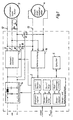
- Figure 1 shows a block diagram of the preferred embodiment of the invention.
- the control circuit 1 shown in Figure 1 has a control and regulating device 2, a DC chopper 14, an inverter 15, a measuring device 16, a memory 5 and connections 12 and 13 for a collectorless motor 3 and a DC collector motor 4.
- Der DC chopper 14 works as a buck converter and converts a fixed input DC voltage, for example of 33 volts, into a variable voltage, which is converted by the inverter 15 for the collectorless motor 3 into a three-phase AC voltage, the phases of which are shifted from one another by 120 °.
- the direct current collector motor 4 its connections are directly connected to the voltage supplied by the direct current controller 14.
- the measuring device 16 is used for EMF detection and measures both the voltage and the current of the connected motor type.
- the control and regulating device 2 is connected to the measuring device 16 and controls or regulates depending on the motor type detected or depending on the motor voltage detected by the measuring device 16 and the detected motor current selected operating parameters, such as the speed or the left / right rotation , of the connected motor.
- the control and regulating device comprises a speed controller 6, a current limiter 7, a brake controller 8, a left / right rotation unit 9, a start / stop unit 10 and a monitoring unit 11, which performs various monitoring functions.
- the monitoring unit 11 can, for example, monitor the temperature of the connected motor or the motor current with regard to a maximum permissible limit value.
- the control and regulating device 2 is supplied with an external target speed value N target.
- the actual control or regulation of the operating parameters of the connected motor is carried out by the control and regulating device, in which it accesses and controls the direct current controller 14 and the inverter 15.
- the connected motor is automatically identified in the following way.
- the control and regulating device applies a measuring voltage U m to two of the three phases of the connection 12 for the collectorless motor 3 via the direct current controller 14 and the inverter 15. In the exemplary embodiment shown in FIG. 1, this measuring voltage U m is applied to the phases V and W.
- the two phases of the connection 13 for the DC collector motor 4 are connected to two of the three phases of the connection 12 for the brushless motor 3, ie the switches 17 and 18 are in the position (1), one of the two phases of the connection 13 for the direct current collector motor 4 is not subjected to the measurement voltage U m , ie in the circuit shown in FIG. 1 the phases of the connection 13 are connected to the phases U and W of the connection 12.
- the measuring device 16 is connected to both connections 12 and 13. Is a three phase brushless motor 3 connected to the terminal 12, flows through the motor winding due to the measuring voltage U m a measurement current I m. If, on the other hand, a DC collector motor 4 is connected to the connection 13, no measuring current I m flows through this motor, since the DC collector motor 4 in this case is not connected to the phase V of the connection 12 to which the measuring voltage U m is applied.
- the measuring device 16 detects the motor current flowing through the connected motor and passes the result on to the control and regulating device 2.
- the control and regulating device 2 compares the detected motor current with a predetermined threshold value and, on the basis of this comparison, concludes the type of the connected small motor.
- the control and regulating device recognizes that a direct current collector motor 4 must be connected. If, on the other hand, the detected motor current is greater than the threshold value, the control and regulating device identifies a connected collectorless motor 3. The result of this identification process is stored in a memory 5 connected to the control and regulating device 2 and remains in the memory 5 until one new engine identification by the control and regulating device 2.
- the control and regulating device 2 carries out a motor identification in each case when the corresponding command signal START is present. If the control and regulating device 2 receives such a start command, the switches 17 and 18 are first set to the position (1) and the connections 12 and 13 are interconnected as shown in FIG. 1 and the motor type by the control and regulating device 2 recognized by applying the measuring voltage U m . The connected motor is not operated by the control circuit 1 while the motor identification is being carried out.
- the result is stored in the memory 5 until the next motor identification and only then is the operation of the connected motor, depending on the detected small motor type, started by the control and regulating device 2 and the operating parameters , such as the speed, of the connected motor controlled or regulated depending on the motor type.
- the connections of the direct current collector motor 4 are directly connected to the voltage supplied by the direct current controller 14, ie the switches 17 and 18 are brought into position (0).
- a dental device with the control circuit shown in FIG. 1 can thus can be equipped with different engine types and the dentist can Select the optimal engine type for each application and use one operate single control circuit.
- control circuit according to the invention is not only for small dental motors, but generally for dental drives can be used in the entire dental field.
Landscapes
- Health & Medical Sciences (AREA)
- Engineering & Computer Science (AREA)
- Animal Behavior & Ethology (AREA)
- General Health & Medical Sciences (AREA)
- Oral & Maxillofacial Surgery (AREA)
- Dentistry (AREA)
- Epidemiology (AREA)
- Life Sciences & Earth Sciences (AREA)
- Power Engineering (AREA)
- Water Supply & Treatment (AREA)
- Public Health (AREA)
- Veterinary Medicine (AREA)
- Control Of Motors That Do Not Use Commutators (AREA)
- Control Of Multiple Motors (AREA)
- Dental Tools And Instruments Or Auxiliary Dental Instruments (AREA)
- Electronic Switches (AREA)
Description
Claims (14)
- Steuerschaltung für dentale Antriebe (3, 4) zum Antrieb eines an einen dentalen Kleinmotor ankoppelbaren zahnärztlichen Instrumentes,
mit einer Steuer- und Regeleinrichtung (2) zum Steuern bzw. Regeln von bestimmten Betriebsparametern des an die Steuerschaltung (1) angeschlossenen dentalen Antriebs (3, 4),
dadurch gekennzeichnet, daß die Steuerschaltung (1) derart ausgebildet ist, daß unterschiedliche Typen von dentalen Antrieben (3, 4) an die Steuerschaltung (1) anschließbar und durch die Steuerschaltung (1) ansteuerbar sind. - Steuerschaltung nach Anspruch 1,
dadurch gekennzeichnet, daß die Steuerschaltung (1) automatisch den Typ des an die Steuerschaltung (1) angeschlossenen dentalen Antriebs (3, 4) erkennt und abhängig von dem erkannten Typ des angeschlossenen dentalen Antriebs (3, 4) über die Steuer- und Regeleinrichtung (2) die bestimmten Betriebsparameter des angeschlossenen dentalen Antriebs (3, 4) steuert bzw. regelt. - Steuerschaltung für dentale Antriebe (3, 4) zum Antrieb eines an einem dentalen Antrieb ankoppelbaren zahnärztlichen Instrumentes,
mit einer Steuer- und Regeleinrichtung (2) zum Steuern bzw. Regeln von bestimmten Betriebsparametern des an die Steuerschaltung (1) angeschlossenen dentalen Antriebs (3, 4),
dadurch gekennzeichnet, daß die Steuerschaltung (1) automatisch den Typ des an die Steuerschaltung (1) angeschlossenen dentalen Antriebs (3, 4) erkennt und abhängig von dem erkannten Typ des angeschlossenen dentalen Antriebs (3, 4) über die Steuer- und Regeleinrichtung (2) die bestimmten Betriebsparameter des angeschlossenen dentalen Antriebs (3, 4) steuert bzw. regelt. - Steuerschaltung nach Anspruch 2 oder 3,
dadurch gekennzeichnet, daß der erkannte Typ des angeschlossenen Kleinmotors (3, 4) in einem Speicher (5) gespeichert wird. - Steuerschaltung nach einem der Ansprüche 2 bis 4,
dadurch gekennzeichnet, daß die Steuerschaltung (1) die Erkennung des Typs des angeschlossenen dentalen Antriebs (3, 4) jeweils bei Vorhandensein eines entsprechenden Befehlssignales (START) durchführt. - Steuerschaltung nach einem der vorhergehenden Ansprüche,
dadurch gekennzeichnet, daß die Steuer- und Regeleinrichtung (2) zum Steuern bzw. Regeln der bestimmten Betriebsparameter einen Drehzahlregler (6) und/oder eine Strombegrenzungseinheit (7) und/oder einen Bremsregler (8) und/oder einen Links-Rechtslaufregler (9) und/oder eine Start-/Stopeinheit (10) und/oder eine Überwachungseinheit (11) zum Überwachen bestimmter Kennwerte der Steuerschaltung (1) oder des angeschlossenen dentalen Antriebs (3, 4) umfaßt. - Steuerschaltung nach einem der vorhergehenden Ansprüche,
dadurch gekennzeichnet, daß der dentale Antrieb ein zahnärztlicher Kleinmotor ist. - Steuerschaltung nach einem der Ansprüche 2-7,
dadurch gekennzeichnet, daß die Steuerschaltung (1) einen Anschluß (12) für einen dreiphasigen kollektorlosen Motor (3) und einen Anschluß (13) für einen zweiphasigen Gleichstrom-Kollektormotor (4) aufweist. - Steuerschaltung nach Anspruch 8,
dadurch gekennzeichnet, daß zwei (U, W) der drei Phasen (U, V, W) des Anschlusses (12) für den dreiphasigen kollektorlosen Motor (3) mit den zwei Phasen des Anschlusses (13) für den zweiphasigen Gleichstrom-Kollektormotor (4) verbunden sind. - Steuerschaltung nach Anspruch 9,
dadurch gekennzeichnet, daß die Steuerschaltung (1) zur Erkennung des Typs des angeschlossenen Kleinmotors (3, 4) eine Meßspannung (Um) an zwei Phasen (V, W) des Anschlusses (12) für den dreiphasigen kollektorlosen Motor (3) anlegt, wobei eine (V) dieser zwei Phasen (V, W) nicht mit den Phasen des Anschlusses (13) für den zweiphasigen Gleichstrom-Kollektormotor (4) verbunden ist, und
daß die Steuerschaltung (1) den aufgrund der Meßspannung (Um) hervorgerufenen und über den angeschlossenen Kleinmotor (3) fließenden Meßstrom (Im) erfaßt und aufgrund des erfaßten Meßstroms (Im) den Typ den angeschlossenen Kleimmotors (3) identifiziert. - Steuerschaltung nach Anspruch 10,
dadurch gekennzeichnet, daß die Steuerschaltung einen an eine Gleichspannung anzuschließenden Gleichstromsteller (14) und einen mit dem Gleichstromsteller (14) eingangsseitig verbundenen Wechselrichter (15) aufweist, wobei der Wechselrichter (5) ausgangsseitig mit dem dreiphasigen Anschluß (12) für den kollektorlosen Motor (3) verbunden ist. - Steuerschaltung nach Anspruch 11,
dadurch gekennzeichnet, daß die Steuer- und Regeleinrichtung (2) den Gleichstromsteller (14) und den Wechselrichter (15) zum Anlegen der Meßspannung (Um) und zum Steuern bzw. Regeln der bestimmten Betriebsparameter des angeschlossenen Kleinmotors (3) abhängig von dem erkannten Typ des angeschlossenen Kleinmotors (3) ansteuert. - Steuerschaltung nach einem der Ansprüche 8 bis 12,
dadurch gekennzeichnet, daß die Steuerschaltung (1) eine Meßeinrichtung (16) zum Erfassen der Motorspannung und des Motorstroms des angeschlossenen Kleinmotors (3) aufweist, die eingangsseitig mit den Anschlüssen (12, 13) für die Kleinmotoren (3, 4) und ausgangsseitig mit der Steuer- und Regeleinrichtung (2) verbunden ist. - Steuerschaltung nach einem der Ansprüche 7 bis 13,
dadurch gekennzeichnet, daß die Betriebsparameter die Motordrehzahl, den Links-/Rechtslaufbetrieb und den Start-/Stopbetrieb der Kleinmotoren (3, 4) umfassen.
Applications Claiming Priority (2)
| Application Number | Priority Date | Filing Date | Title |
|---|---|---|---|
| DE19604627A DE19604627A1 (de) | 1996-02-08 | 1996-02-08 | Steuerschaltung für dentale Antriebe |
| DE19604627 | 1996-02-08 |
Publications (3)
| Publication Number | Publication Date |
|---|---|
| EP0788778A2 EP0788778A2 (de) | 1997-08-13 |
| EP0788778A3 EP0788778A3 (de) | 1998-01-21 |
| EP0788778B1 true EP0788778B1 (de) | 2001-10-17 |
Family
ID=7784883
Family Applications (1)
| Application Number | Title | Priority Date | Filing Date |
|---|---|---|---|
| EP96118914A Expired - Lifetime EP0788778B1 (de) | 1996-02-08 | 1996-11-26 | Steuerschaltung für dentale Antriebe |
Country Status (3)
| Country | Link |
|---|---|
| EP (1) | EP0788778B1 (de) |
| AT (1) | ATE206900T1 (de) |
| DE (2) | DE19604627A1 (de) |
Families Citing this family (7)
| Publication number | Priority date | Publication date | Assignee | Title |
|---|---|---|---|---|
| JP2002335699A (ja) * | 2001-05-09 | 2002-11-22 | Hitachi Ltd | 交流モータの制御装置 |
| DE10225857A1 (de) * | 2002-06-11 | 2004-01-22 | Aesculap Ag & Co. Kg | Chirurgisches Motorensystem |
| DE102008024438A1 (de) | 2008-05-14 | 2009-11-19 | Aesculap Ag | Chirurgische Antriebseinheit, chirurgisches Instrument und chirurgisches Antriebssystem |
| EP2201907B1 (de) | 2008-12-24 | 2013-12-18 | W & H Dentalwerk Bürmoos GmbH | Verfahren und Vorrichtung zum Programmieren eines zur Wurzelkanalaufbereitung dienenden schnurlosen Handstücks |
| DE102010009662A1 (de) * | 2010-02-27 | 2011-09-01 | Volkswagen Ag | Verfahren zur Parametrierung eines Steuergeräts für ein Fahrzeug sowie entsprechendes Steuergerät und Fahrzeug |
| DE102012211464A1 (de) * | 2012-07-03 | 2014-01-09 | Robert Bosch Gmbh | Automatische Identifizierung eines elektronisch kommutierten Motors |
| CN112671274A (zh) * | 2020-12-17 | 2021-04-16 | 中国航空工业集团公司成都飞机设计研究所 | 一种通用电机控制系统和方法 |
Family Cites Families (4)
| Publication number | Priority date | Publication date | Assignee | Title |
|---|---|---|---|---|
| FR2233030B1 (de) * | 1973-06-12 | 1977-02-11 | Kaltenbach & Voigt | |
| FR2397180A1 (fr) * | 1977-07-13 | 1979-02-09 | Lear Avia Corp | Perceuse dentaire a moteur electrique |
| EP0409226A3 (en) * | 1989-07-21 | 1993-01-13 | Hitachi, Ltd. | Power supply control system |
| DE4412413C1 (de) | 1994-04-11 | 1995-05-11 | Siemens Ag | Einrichtung zur Optimierung des Drehzahlregelverhaltens eines Elektrokleinstmotors für zahnärztliche Zwecke |
-
1996
- 1996-02-08 DE DE19604627A patent/DE19604627A1/de not_active Withdrawn
- 1996-11-26 DE DE59607947T patent/DE59607947D1/de not_active Expired - Lifetime
- 1996-11-26 AT AT96118914T patent/ATE206900T1/de active
- 1996-11-26 EP EP96118914A patent/EP0788778B1/de not_active Expired - Lifetime
Also Published As
| Publication number | Publication date |
|---|---|
| EP0788778A2 (de) | 1997-08-13 |
| EP0788778A3 (de) | 1998-01-21 |
| DE19604627A1 (de) | 1997-08-14 |
| DE59607947D1 (de) | 2001-11-22 |
| ATE206900T1 (de) | 2001-11-15 |
Similar Documents
| Publication | Publication Date | Title |
|---|---|---|
| DE4009258C2 (de) | Verfahren und elektronische Regelschaltung zum Anlassen eines bürstenlosen Gleitstrommotors | |
| DE4124240C2 (de) | Verfahren zur Regelung des Motorstroms eines bürstenlosen Gleichstommotors | |
| DE19846831B4 (de) | Verfahren und Vorrichtung zur Ermittlung der Rotorstellung von Synchronmotoren | |
| DE69312871T2 (de) | Elektrische Servolenkung | |
| DE60217013T2 (de) | Steuervorrichtung für eine Wechselstromquelle | |
| EP1727268A2 (de) | Verfahren zum Betrieben eines elektronisch kommutierten Motors, und Motor zur Durchführung eines solchen Verfahrens | |
| DE202004012389U1 (de) | Chirurgische Maschine | |
| DE102004052652A1 (de) | Motorantriebssystem | |
| DE19860446A1 (de) | Verfahren zur Regelung eines spannungs-/frequenzumrichtergesteuerten Mehrphasen-Permanentmagnetmotors | |
| EP1889355A1 (de) | Verfahren und vorrichtung zum steuern eines bürstenlosen gleichstrommotors | |
| DE3876675T2 (de) | Regulierungssysteme fuer buerstenlose motoren. | |
| DE19604627A1 (de) | Steuerschaltung für dentale Antriebe | |
| DE69215632T2 (de) | Starten von Mehrfachgeschwindigkeitsmotoren von einer niedrigen Geschwindigkeitsverbindung aus | |
| EP1708354B1 (de) | Tauchmotor | |
| EP1071200A2 (de) | Elektronisch kommutierbarer Motor | |
| DE69708351T2 (de) | Gerät zur Detektion der externen Induktion für die Kommutierung eines Motors mit veränderlicher Reluktanz | |
| DE3523177C2 (de) | ||
| DE3609678C2 (de) | Antriebsanordnung mit kollektorlosem Gleichstrommotor | |
| DE102017127410A1 (de) | Verfahren und Schaltungsanordnung zur Ermittlung der Stellung eines Rotors eines Elektromotors | |
| DE102021214720A1 (de) | Steuereinrichtung zum Steuern eines bürstenlosen Gleichstrommotors unter Verwendung einer Totzeit-Kompensation | |
| DE10338996A1 (de) | Verfahren zur Steuerung eines bürstenlosen Elektromotors | |
| DE19809764C2 (de) | Verfahren und Vorrichtung zur Steuerung eines elektronisch kommutierten Gleichstrommotors | |
| DE19953265B4 (de) | Verfahren zum Anfahren eines Gleichstrommotors | |
| DE102015204396A1 (de) | Steuerung und Verfahren zum Anfahren eines bürstenlosen Gleichstrommotors | |
| DE10221385A1 (de) | Verfahren zum Starten eines bürstenlosen Gleichstrommotors |
Legal Events
| Date | Code | Title | Description |
|---|---|---|---|
| PUAI | Public reference made under article 153(3) epc to a published international application that has entered the european phase |
Free format text: ORIGINAL CODE: 0009012 |
|
| AK | Designated contracting states |
Kind code of ref document: A2 Designated state(s): AT CH DE FR IT LI |
|
| PUAL | Search report despatched |
Free format text: ORIGINAL CODE: 0009013 |
|
| AK | Designated contracting states |
Kind code of ref document: A3 Designated state(s): AT CH DE FR IT LI |
|
| 17P | Request for examination filed |
Effective date: 19980429 |
|
| GRAG | Despatch of communication of intention to grant |
Free format text: ORIGINAL CODE: EPIDOS AGRA |
|
| GRAG | Despatch of communication of intention to grant |
Free format text: ORIGINAL CODE: EPIDOS AGRA |
|
| GRAH | Despatch of communication of intention to grant a patent |
Free format text: ORIGINAL CODE: EPIDOS IGRA |
|
| 17Q | First examination report despatched |
Effective date: 20010313 |
|
| GRAH | Despatch of communication of intention to grant a patent |
Free format text: ORIGINAL CODE: EPIDOS IGRA |
|
| GRAA | (expected) grant |
Free format text: ORIGINAL CODE: 0009210 |
|
| AK | Designated contracting states |
Kind code of ref document: B1 Designated state(s): AT CH DE FR IT LI |
|
| REF | Corresponds to: |
Ref document number: 206900 Country of ref document: AT Date of ref document: 20011115 Kind code of ref document: T |
|
| REG | Reference to a national code |
Ref country code: CH Ref legal event code: NV Representative=s name: A. BRAUN, BRAUN, HERITIER, ESCHMANN AG PATENTANWAE Ref country code: CH Ref legal event code: EP |
|
| REF | Corresponds to: |
Ref document number: 59607947 Country of ref document: DE Date of ref document: 20011122 |
|
| ET | Fr: translation filed | ||
| PLBE | No opposition filed within time limit |
Free format text: ORIGINAL CODE: 0009261 |
|
| STAA | Information on the status of an ep patent application or granted ep patent |
Free format text: STATUS: NO OPPOSITION FILED WITHIN TIME LIMIT |
|
| 26N | No opposition filed | ||
| REG | Reference to a national code |
Ref country code: CH Ref legal event code: PFA Owner name: KALTENBACH & VOIGT GMBH & CO. Free format text: KALTENBACH & VOIGT GMBH & CO.#BISMARCKRING 39#88400 BIBERACH (DE) -TRANSFER TO- KALTENBACH & VOIGT GMBH & CO.#BISMARCKRING 39#88400 BIBERACH (DE) |
|
| PGFP | Annual fee paid to national office [announced via postgrant information from national office to epo] |
Ref country code: FR Payment date: 20101209 Year of fee payment: 15 Ref country code: AT Payment date: 20101122 Year of fee payment: 15 |
|
| PGFP | Annual fee paid to national office [announced via postgrant information from national office to epo] |
Ref country code: DE Payment date: 20101201 Year of fee payment: 15 Ref country code: CH Payment date: 20101130 Year of fee payment: 15 |
|
| PGFP | Annual fee paid to national office [announced via postgrant information from national office to epo] |
Ref country code: IT Payment date: 20101119 Year of fee payment: 15 |
|
| REG | Reference to a national code |
Ref country code: CH Ref legal event code: PL |
|
| PG25 | Lapsed in a contracting state [announced via postgrant information from national office to epo] |
Ref country code: LI Free format text: LAPSE BECAUSE OF NON-PAYMENT OF DUE FEES Effective date: 20111130 Ref country code: CH Free format text: LAPSE BECAUSE OF NON-PAYMENT OF DUE FEES Effective date: 20111130 |
|
| REG | Reference to a national code |
Ref country code: FR Ref legal event code: ST Effective date: 20120731 |
|
| PG25 | Lapsed in a contracting state [announced via postgrant information from national office to epo] |
Ref country code: IT Free format text: LAPSE BECAUSE OF NON-PAYMENT OF DUE FEES Effective date: 20111126 |
|
| REG | Reference to a national code |
Ref country code: DE Ref legal event code: R119 Ref document number: 59607947 Country of ref document: DE Effective date: 20120601 |
|
| REG | Reference to a national code |
Ref country code: AT Ref legal event code: MM01 Ref document number: 206900 Country of ref document: AT Kind code of ref document: T Effective date: 20111126 |
|
| PG25 | Lapsed in a contracting state [announced via postgrant information from national office to epo] |
Ref country code: FR Free format text: LAPSE BECAUSE OF NON-PAYMENT OF DUE FEES Effective date: 20111130 |
|
| PG25 | Lapsed in a contracting state [announced via postgrant information from national office to epo] |
Ref country code: AT Free format text: LAPSE BECAUSE OF NON-PAYMENT OF DUE FEES Effective date: 20111126 |
|
| PG25 | Lapsed in a contracting state [announced via postgrant information from national office to epo] |
Ref country code: DE Free format text: LAPSE BECAUSE OF NON-PAYMENT OF DUE FEES Effective date: 20120601 |