EP0788432B1 - Tintenstrahldrucker - Google Patents
Tintenstrahldrucker Download PDFInfo
- Publication number
- EP0788432B1 EP0788432B1 EP95934740A EP95934740A EP0788432B1 EP 0788432 B1 EP0788432 B1 EP 0788432B1 EP 95934740 A EP95934740 A EP 95934740A EP 95934740 A EP95934740 A EP 95934740A EP 0788432 B1 EP0788432 B1 EP 0788432B1
- Authority
- EP
- European Patent Office
- Prior art keywords
- armature
- orifices
- slots
- disposed
- transducer
- Prior art date
- Legal status (The legal status is an assumption and is not a legal conclusion. Google has not performed a legal analysis and makes no representation as to the accuracy of the status listed.)
- Expired - Lifetime
Links
- 239000012530 fluid Substances 0.000 claims description 3
- 230000005540 biological transmission Effects 0.000 description 2
- 238000005452 bending Methods 0.000 description 1
- 238000010276 construction Methods 0.000 description 1
- 239000000463 material Substances 0.000 description 1
- 229910001220 stainless steel Inorganic materials 0.000 description 1
- 239000010935 stainless steel Substances 0.000 description 1
Images


Classifications
-
- B—PERFORMING OPERATIONS; TRANSPORTING
- B41—PRINTING; LINING MACHINES; TYPEWRITERS; STAMPS
- B41J—TYPEWRITERS; SELECTIVE PRINTING MECHANISMS, i.e. MECHANISMS PRINTING OTHERWISE THAN FROM A FORME; CORRECTION OF TYPOGRAPHICAL ERRORS
- B41J2/00—Typewriters or selective printing mechanisms characterised by the printing or marking process for which they are designed
- B41J2/005—Typewriters or selective printing mechanisms characterised by the printing or marking process for which they are designed characterised by bringing liquid or particles selectively into contact with a printing material
- B41J2/01—Ink jet
- B41J2/015—Ink jet characterised by the jet generation process
- B41J2/02—Ink jet characterised by the jet generation process generating a continuous ink jet
- B41J2/025—Ink jet characterised by the jet generation process generating a continuous ink jet by vibration
Definitions
- the present invention relates to ink jet printers and, more particularly, to an actuator drive for a multi-jet continuous ink jet printer.
- EP-A-0 126 649 discloses a multi-jet continuous ink jet print head having a transducer unit mounted within an ink chamber.
- the transducer unit is made of a piezoelectric material and is provided with a number of slots to prevent wave transmission and bending along the length or said transducer.
- a multi-jet continuous ink Jet printhead having an ink chamber, the chamber having a plurality of orifices for the emission of fluid droplets therefrom, and an actuator drive armature with a plurality of elongate slots therethrough disposed in a row, characterised in that
- the number of slots is one less than the number of orifices in the printhead, so that a land is aligned with each orifice.
- the number of transducer mountings is equal to the number of orifices in the printhead, but in alternative constructions the number of transducer mountings may be less than the number of orifices.
- the armature may have a number of lands greater then the number of transducers employed.
- the armature plate is slit at positions between the transducer mountings parallel with the slots in the armature, in order to reduce crosstalk between adjacent transducers in use.
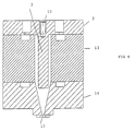
- the actuator drive armature 1 comprises a stainless steel member having a mounting flange 2 by means of which the armature is secured within an ink chamber 11 defined by a body 13 and orifice plate 14. Extending perpendicularly away from the flange 2 on one side is a drive wall 3 which has a lower surface 4 which, in use, is disposed above orifices 12 in orifice plate 14 from which ink is ejected from the ink chamber 11.
- the drive wall 3 has a plurality of elongate slots 5 formed through it at a pitch corresponding to the pitch of the orifices 12, thereby forming a series of lands 6, each of which is disposed, in use, above a respective orifice 12.
- An upward extension 7 of the wall 3 is formed as a series of square-sectioned protrusions 8, separated from one another by slits 9 and having central bores 10 by means of which individual piezoelectric transducers can be mounted onto the armature in order to cause it to vibrate in use.
- the slits 10 between the mounting protrusions 8 act to reduce cross-talk between individual piezoelectric transducers.
Landscapes
- Particle Formation And Scattering Control In Inkjet Printers (AREA)
Claims (6)
- Mehrstrahliger, kontinuierlich arbeitender Tintenstrahl-Druckkopf mit einer Tintenkammer (11), die eine Mehrzahl Öffnungen (12) zum Ausstoßen von Flüssigkeitstropfen aus der Kammer (11) aufweist, und einer Betätigungs-Antriebs-Armatur (1) mit einer Mehrzahl länglicher Schlitze (5) dadurch, die in einer Reihe angeordnet sind, dadurch gekennzeichnet, daßdie Armatur (1) innerhalb der Tintenkammer (11) angeordnet ist und eine Reihe Wandler-Halterungen (8) an einer Seite und eine Antriebs-Wand (3) an der anderen Seite hat, wobei die Schlitze (5) in der Antriebs-Wand (3) in einer Reihe parallel zu der anderen Seite der Armatur (1) angeordnet sind und jeder Schlitz (5) sich von der einen Seite weg erstreckt und zwischen den Wandler-Halterungen (8) ausgerichtet ist, wodurch Stege (6) zwischen den Schlitzen (5) mit den Wandler-Halterungen (8) ausgerichtet sind.
- Druckkopf nach Anspruch 1, bei dem die Armatur (1) Einschnitte (9) an Positionen zwischen den Wandler-Halterungen (8), parallel zu den Schlitzen (5) in der Antriebs-Wand (3) hat, um eine gegenseitige Beeinflussung zwischen benachbarten Wandlern im Gebrauch zu vermindern.
- Druckkopf nach Anspruch 1 oder Anspruch 2, bei dem die Anzahl Schlitze (5) in der Antriebs-Wand (3) der Armatur um 1 kleiner als die Anzahl an Öffnungen (12) in der Kammer ist, so daß mit jeder Öffnung (12) einer der Stege (6) ausgerichtet ist.
- Druckkopf nach Anspruch 3, bei dem die Anzahl Wandler-Halterungen (8) gleich der Anzahl Öffnungen (12) in der Tintenkammer (11) ist.
- Druckkopf nach Anspruch 3, bei dem die Anzahl Wandler-Halterungen (8) geringer als die Anzahl Öffnungen (12) in der Tintenkammer (11) ist.
- Druckkopf nach irgendeinem der Ansprüche 1 bis 5, bei dem die Öffnungen (12) in einer Öffnungs-Platte (14) angeordnet sind.
Applications Claiming Priority (3)
| Application Number | Priority Date | Filing Date | Title |
|---|---|---|---|
| GB9421393 | 1994-10-24 | ||
| GB9421393A GB9421393D0 (en) | 1994-10-24 | 1994-10-24 | Ink jet printer |
| PCT/GB1995/002515 WO1996012622A1 (en) | 1994-10-24 | 1995-10-23 | Ink jet printer |
Publications (2)
| Publication Number | Publication Date |
|---|---|
| EP0788432A1 EP0788432A1 (de) | 1997-08-13 |
| EP0788432B1 true EP0788432B1 (de) | 1998-12-23 |
Family
ID=10763287
Family Applications (1)
| Application Number | Title | Priority Date | Filing Date |
|---|---|---|---|
| EP95934740A Expired - Lifetime EP0788432B1 (de) | 1994-10-24 | 1995-10-23 | Tintenstrahldrucker |
Country Status (6)
| Country | Link |
|---|---|
| US (1) | US5912686A (de) |
| EP (1) | EP0788432B1 (de) |
| JP (1) | JPH10507701A (de) |
| DE (1) | DE69506905T2 (de) |
| GB (1) | GB9421393D0 (de) |
| WO (1) | WO1996012622A1 (de) |
Families Citing this family (7)
| Publication number | Priority date | Publication date | Assignee | Title |
|---|---|---|---|---|
| GB9617908D0 (en) * | 1996-08-28 | 1996-10-09 | Videojet Systems Int | A droplet generator for a continuous stream ink jet print head |
| GB9626705D0 (en) * | 1996-12-23 | 1997-02-12 | Domino Printing Sciences Plc | Ink jet printer |
| JPH11306579A (ja) * | 1998-04-15 | 1999-11-05 | Sony Corp | ビームスプリッタ及び光ピックアップ装置 |
| JP4844119B2 (ja) * | 2005-12-26 | 2011-12-28 | 株式会社日立製作所 | 液滴形成装置およびそれを用いたインクジェット記録装置 |
| CN105555538B (zh) * | 2013-08-27 | 2017-07-21 | 录象射流技术公司 | 用于连续流喷墨打印头的微滴发生器 |
| US9889664B2 (en) | 2013-09-20 | 2018-02-13 | Hewlett-Packard Development Company, L.P. | Molded printhead structure |
| CN105555539B (zh) * | 2013-09-20 | 2017-08-15 | 惠普发展公司,有限责任合伙企业 | 打印杆以及形成打印杆的方法 |
Family Cites Families (4)
| Publication number | Priority date | Publication date | Assignee | Title |
|---|---|---|---|---|
| US4138687A (en) * | 1977-07-18 | 1979-02-06 | The Mead Corporation | Apparatus for producing multiple uniform fluid filaments and drops |
| US4554558A (en) * | 1983-05-19 | 1985-11-19 | The Mead Corporation | Fluid jet print head |
| EP0126649B1 (de) * | 1983-05-19 | 1988-04-13 | The Mead Corporation | Flüssigkeitsstrahldruckkopf |
| US4999647A (en) * | 1989-12-28 | 1991-03-12 | Eastman Kodak Company | Synchronous stimulation for long array continuous ink jet printer |
-
1994
- 1994-10-24 GB GB9421393A patent/GB9421393D0/en active Pending
-
1995
- 1995-10-23 WO PCT/GB1995/002515 patent/WO1996012622A1/en not_active Ceased
- 1995-10-23 EP EP95934740A patent/EP0788432B1/de not_active Expired - Lifetime
- 1995-10-23 DE DE69506905T patent/DE69506905T2/de not_active Expired - Fee Related
- 1995-10-23 JP JP8513740A patent/JPH10507701A/ja active Pending
- 1995-10-23 US US08/793,594 patent/US5912686A/en not_active Expired - Fee Related
Also Published As
| Publication number | Publication date |
|---|---|
| JPH10507701A (ja) | 1998-07-28 |
| DE69506905T2 (de) | 1999-05-12 |
| GB9421393D0 (en) | 1994-12-07 |
| US5912686A (en) | 1999-06-15 |
| EP0788432A1 (de) | 1997-08-13 |
| DE69506905D1 (de) | 1999-02-04 |
| WO1996012622A1 (en) | 1996-05-02 |
Similar Documents
| Publication | Publication Date | Title |
|---|---|---|
| US5790155A (en) | Ink jet type recording head having head units with angled walls and angled pressure generating chambers | |
| US8191982B2 (en) | Liquid projection apparatus | |
| US8317299B2 (en) | Liquid projection apparatus | |
| US4980703A (en) | Print head for ink-jet printing apparatus | |
| EP0783409B1 (de) | Tintenstrahlvorrichtung mit einer vielzahl von kammern mit mehreren düsen | |
| US4420764A (en) | Ink jet printer head | |
| EP1815991B1 (de) | Piezoelektrischer Tintenstrahldruckkopf | |
| US20100039480A1 (en) | Liquid Projection Apparatus - Vista RLCT | |
| EP0788432B1 (de) | Tintenstrahldrucker | |
| US6467885B2 (en) | Ink jet record head | |
| US5394181A (en) | Air bubble removal in a drop on demand ink jet print head | |
| JP2850762B2 (ja) | インクジェットヘッド | |
| US4703330A (en) | Color ink jet drop generator using a solid acoustic cavity | |
| CN100361818C (zh) | 喷墨头控制器、喷墨头的控制方法以及喷墨记录装置 | |
| JP3173561B2 (ja) | 積層型インクジェット式記録ヘッド、及びこれの駆動方法 | |
| JP4671029B2 (ja) | インク滴吐出装置 | |
| JPS6325944B2 (de) | ||
| WO2008044073A1 (en) | Liquid projection apparatus | |
| EP0966356B1 (de) | Tintenstrahldrucker | |
| JPH0852873A (ja) | インクジェット式プリンタヘッド及びその駆動方法 | |
| JPH09174836A (ja) | インクジェット記録ヘッド及びその製造方法 | |
| JP2023144261A (ja) | プリントヘッドの駆動方法 | |
| JPH0557889A (ja) | インクジエツト記録ヘツド | |
| JPH08207276A (ja) | インクジェットプリントヘッド | |
| JPS59178257A (ja) | インクジエツトヘツド |
Legal Events
| Date | Code | Title | Description |
|---|---|---|---|
| PUAI | Public reference made under article 153(3) epc to a published international application that has entered the european phase |
Free format text: ORIGINAL CODE: 0009012 |
|
| 17P | Request for examination filed |
Effective date: 19970516 |
|
| AK | Designated contracting states |
Kind code of ref document: A1 Designated state(s): DE FR GB IT |
|
| GRAG | Despatch of communication of intention to grant |
Free format text: ORIGINAL CODE: EPIDOS AGRA |
|
| 17Q | First examination report despatched |
Effective date: 19970919 |
|
| GRAG | Despatch of communication of intention to grant |
Free format text: ORIGINAL CODE: EPIDOS AGRA |
|
| GRAH | Despatch of communication of intention to grant a patent |
Free format text: ORIGINAL CODE: EPIDOS IGRA |
|
| GRAH | Despatch of communication of intention to grant a patent |
Free format text: ORIGINAL CODE: EPIDOS IGRA |
|
| GRAA | (expected) grant |
Free format text: ORIGINAL CODE: 0009210 |
|
| AK | Designated contracting states |
Kind code of ref document: B1 Designated state(s): DE FR GB IT |
|
| PG25 | Lapsed in a contracting state [announced via postgrant information from national office to epo] |
Ref country code: IT Free format text: LAPSE BECAUSE OF FAILURE TO SUBMIT A TRANSLATION OF THE DESCRIPTION OR TO PAY THE FEE WITHIN THE PRE;WARNING: LAPSES OF ITALIAN PATENTS WITH EFFECTIVE DATE BEFORE 2007 MAY HAVE OCCURRED AT ANY TIME BEFORE 2007. THE CORRECT EFFECTIVE DATE MAY BE DIFFERENT FROM THE ONE RECORDED.SCRIBED TIME-LIMIT Effective date: 19981223 |
|
| REF | Corresponds to: |
Ref document number: 69506905 Country of ref document: DE Date of ref document: 19990204 |
|
| ET | Fr: translation filed | ||
| PGFP | Annual fee paid to national office [announced via postgrant information from national office to epo] |
Ref country code: FR Payment date: 19991011 Year of fee payment: 5 |
|
| PGFP | Annual fee paid to national office [announced via postgrant information from national office to epo] |
Ref country code: GB Payment date: 19991020 Year of fee payment: 5 |
|
| PGFP | Annual fee paid to national office [announced via postgrant information from national office to epo] |
Ref country code: DE Payment date: 19991022 Year of fee payment: 5 |
|
| PLBE | No opposition filed within time limit |
Free format text: ORIGINAL CODE: 0009261 |
|
| STAA | Information on the status of an ep patent application or granted ep patent |
Free format text: STATUS: NO OPPOSITION FILED WITHIN TIME LIMIT |
|
| 26N | No opposition filed | ||
| PG25 | Lapsed in a contracting state [announced via postgrant information from national office to epo] |
Ref country code: GB Free format text: LAPSE BECAUSE OF NON-PAYMENT OF DUE FEES Effective date: 20001023 |
|
| GBPC | Gb: european patent ceased through non-payment of renewal fee |
Effective date: 20001023 |
|
| PG25 | Lapsed in a contracting state [announced via postgrant information from national office to epo] |
Ref country code: FR Free format text: LAPSE BECAUSE OF NON-PAYMENT OF DUE FEES Effective date: 20010629 |
|
| PG25 | Lapsed in a contracting state [announced via postgrant information from national office to epo] |
Ref country code: DE Free format text: LAPSE BECAUSE OF NON-PAYMENT OF DUE FEES Effective date: 20010703 |
|
| REG | Reference to a national code |
Ref country code: FR Ref legal event code: ST |