EP0788423B1 - Verbesserungen in bezug auf die auskleidung von rohrleitungen und durchgängen - Google Patents
Verbesserungen in bezug auf die auskleidung von rohrleitungen und durchgängen Download PDFInfo
- Publication number
- EP0788423B1 EP0788423B1 EP95932847A EP95932847A EP0788423B1 EP 0788423 B1 EP0788423 B1 EP 0788423B1 EP 95932847 A EP95932847 A EP 95932847A EP 95932847 A EP95932847 A EP 95932847A EP 0788423 B1 EP0788423 B1 EP 0788423B1
- Authority
- EP
- European Patent Office
- Prior art keywords
- energy
- waveguide
- pipeline
- passageway
- lining
- Prior art date
- Legal status (The legal status is an assumption and is not a legal conclusion. Google has not performed a legal analysis and makes no representation as to the accuracy of the status listed.)
- Expired - Lifetime
Links
Images


Classifications
-
- B—PERFORMING OPERATIONS; TRANSPORTING
- B29—WORKING OF PLASTICS; WORKING OF SUBSTANCES IN A PLASTIC STATE IN GENERAL
- B29C—SHAPING OR JOINING OF PLASTICS; SHAPING OF MATERIAL IN A PLASTIC STATE, NOT OTHERWISE PROVIDED FOR; AFTER-TREATMENT OF THE SHAPED PRODUCTS, e.g. REPAIRING
- B29C63/00—Lining or sheathing, i.e. applying preformed layers or sheathings of plastics; Apparatus therefor
- B29C63/0065—Heat treatment
- B29C63/0069—Heat treatment of tubular articles
-
- B—PERFORMING OPERATIONS; TRANSPORTING
- B29—WORKING OF PLASTICS; WORKING OF SUBSTANCES IN A PLASTIC STATE IN GENERAL
- B29C—SHAPING OR JOINING OF PLASTICS; SHAPING OF MATERIAL IN A PLASTIC STATE, NOT OTHERWISE PROVIDED FOR; AFTER-TREATMENT OF THE SHAPED PRODUCTS, e.g. REPAIRING
- B29C35/00—Heating, cooling or curing, e.g. crosslinking or vulcanising; Apparatus therefor
- B29C35/02—Heating or curing, e.g. crosslinking or vulcanizing during moulding, e.g. in a mould
- B29C35/08—Heating or curing, e.g. crosslinking or vulcanizing during moulding, e.g. in a mould by wave energy or particle radiation
- B29C35/10—Heating or curing, e.g. crosslinking or vulcanizing during moulding, e.g. in a mould by wave energy or particle radiation for articles of indefinite length
-
- F—MECHANICAL ENGINEERING; LIGHTING; HEATING; WEAPONS; BLASTING
- F16—ENGINEERING ELEMENTS AND UNITS; GENERAL MEASURES FOR PRODUCING AND MAINTAINING EFFECTIVE FUNCTIONING OF MACHINES OR INSTALLATIONS; THERMAL INSULATION IN GENERAL
- F16L—PIPES; JOINTS OR FITTINGS FOR PIPES; SUPPORTS FOR PIPES, CABLES OR PROTECTIVE TUBING; MEANS FOR THERMAL INSULATION IN GENERAL
- F16L55/00—Devices or appurtenances for use in, or in connection with, pipes or pipe systems
- F16L55/16—Devices for covering leaks in pipes or hoses, e.g. hose-menders
- F16L55/162—Devices for covering leaks in pipes or hoses, e.g. hose-menders from inside the pipe
- F16L55/165—Devices for covering leaks in pipes or hoses, e.g. hose-menders from inside the pipe a pipe or flexible liner being inserted in the damaged section
-
- B—PERFORMING OPERATIONS; TRANSPORTING
- B29—WORKING OF PLASTICS; WORKING OF SUBSTANCES IN A PLASTIC STATE IN GENERAL
- B29C—SHAPING OR JOINING OF PLASTICS; SHAPING OF MATERIAL IN A PLASTIC STATE, NOT OTHERWISE PROVIDED FOR; AFTER-TREATMENT OF THE SHAPED PRODUCTS, e.g. REPAIRING
- B29C35/00—Heating, cooling or curing, e.g. crosslinking or vulcanising; Apparatus therefor
- B29C35/02—Heating or curing, e.g. crosslinking or vulcanizing during moulding, e.g. in a mould
- B29C35/08—Heating or curing, e.g. crosslinking or vulcanizing during moulding, e.g. in a mould by wave energy or particle radiation
- B29C35/0805—Heating or curing, e.g. crosslinking or vulcanizing during moulding, e.g. in a mould by wave energy or particle radiation using electromagnetic radiation
- B29C2035/0855—Heating or curing, e.g. crosslinking or vulcanizing during moulding, e.g. in a mould by wave energy or particle radiation using electromagnetic radiation using microwave
Definitions
- This invention relates to the lining of pipelines and passageways, and concerns a means and method whereby a lining tube which is placed on the inner surface of a pipeline or passageway is subjected to a radiation treatment which has an effect on the material of the lining tube, for a purpose which will appear clear hereinafter.
- CIP cured in place
- a tube of resin absorbent material is soaked in a curable synthetic resin, and the tube whilst still flexible in nature is introduced into the pipeline or passageway and is inflated onto the pipeline or passageway surface so as to lie thereon and conform thereto. Whilst the tube is so held, the resin is allowed or caused to cure (usually heat is applied to accelerate curing) so that there results a hard lining pipe lying on the pipeline or passageway surface.
- Basic procedures for carrying out this method are set forth in US patents 4009063 and 4064211, although many subsequent patents have been obtained for improvements in the basic process.
- thermoplastic material tube is introduced into the pipeline or passageway, and it is subjected to heat so as to soften the plastics material.
- An internal pressure forces the soft pipe onto the pipeline or passageway surface, and then the pipe is cooled so that the inflated and reshaped thermoplastic pipe forms a lining which functions in a similar manner to a CIP lining discussed above.
- the heat may be applied to the thermoplastic material at any convenient position e.g. before the thermoplastic material is introduced into the pipeline or passageway or after it is introduced, or both.
- European Patent Application 0241297 discloses a device for heating plastic pipe linings wherein the device is a heater having end seals to seal against the pipe lining.
- Swiss Patent No. 676029 discloses a number of techniques for the curing of a CIP lining including conductive heating, light, gas, electrical heating and heating by micro waves, but in relation to the last form of heating, namely micro waves, with which the present invention is concerned, no specific details are given as to how the micro waves might be used and therefore gives no indication of the economic and efficient use of the micro waves. It is for example important that the entire lining be treated with the energy for the even curing of the lining.
- the present invention is concerned with the use of micro wave in a particular manner which gives even and economical application of the micro wave energy.
- the present invention applies to each of the indicated lining methods, but it has particular application to CIP linings which are of a nature such that the resin contained therein will remain "quiescent" until activated by some external means.
- CIP linings with this resin system are described as having a latent resin system.
- the advantage of this is that the linings can be manufactured and impregnated at some considerable time before they have to be used. In other words impregnated linings can be stored in stock, and then taken from stock to order. This differs from the normal method of performing CIP processes wherein the resin is applied to the lining tube shortly before it is to be used, and the impregnated lining is taken to the site as soon as possible after impregnation so that premature curing will not take place. Indeed, many CIP processes involve impregnating the lining at the location of the site.
- latent resin systems have not been utilised to any substantial extent and this invention seeks to provide a method and means whereby latent curing systems can be utilised efficiently and reliably.
- the method and means can also be used for the treatment of thermoplastic pipes for the softening of same.
- a method of lining a pipeline or passageway wherein a lining tube positioned in the pipeline or passageway has an apparatus passed therethrough, and the apparatus provides microwave energy radially directed at the inside of the lining tube, and the lining tube is sensitive to that energy in either of two ways namely (i) it has a curable resin therein which is cured by the application of the energy or (ii) it is thermoplastic and contains a particulate polar material which heats up under the action of the microwave energy to soften the tube so that it can be expanded, characterised in that the microwave energy is in the form of one or more radial streams which are rotated about the axis of the pipeline or passageway as the apparatus is passed through the lining tube.
- the said one or more radial streams is/are rotated by rotation of the waveguide and the energy generating source may be part of the apparatus, and may be arranged to direct a stream of microwave energy radially and is rotated about the axis of the pipeline or passageway.
- the energy is supplied through a coaxial cable to a dipole which is arranged to emit the energy radially of the pipeline or passageway, and in a particular form, the energy is focused by a reflector into a beam, and the reflector is rotatable to cause the beam to rotate peripherally of the lining tube.
- the invention also provides apparatus for performing the method as aforesain, comprising a microwave energy source, a waveguide adapted to direct energy from the source radially into the lining tube, and means to cause progression of the radially directed energy circumferentially of the lining tube.
- said waveguide may be rotatable relative to the microwave energy source to effect said circumferential progression, whilst in another case the microwave energy source is fixed relative to the waveguide.
- the microwave energy source may be mounted for rotation with the waveguide.
- the energy source may include a dipole at the end of a coaxial cable.
- the waveguide may comprise spaced discs with the reflector beng adapted to be rotated around the dipole.
- the waveguide may be in the form of one or more arms.
- an apparatus for heating a lining of a pipeline or passageway comprises a microwave energy source, a waveguide adapted to direct energy from the source radially into the lining tube, said waveguide comprising a pair of spaced discs adapted to lie with their planes transverse to the axis of the pipeline or passageway.
- the discs may have sealing members at the periphery thereof to seal against the pipeline or passageway surface and the microwave energy source may comprises an antenna at the centre of the waveguide.
- the energy source comprises a magnetron connected to the antenna but located outside the waveguide, and the magnetron may be contained in an insulated canister along with other electrical components to provide the required output from the magnetron, and the canister is adapted to travel along the pipeline or passageway with the waveguide, and power is supplied thereto by an electrical cable.
- the lining tube is a thermoplastic tube, it will require to have embedded therein particles which are polar in nature i.e. they are sensitive to the microwave energy so that the particles heat up, as the plastics material in itself is unlikely to be affected by microwave energy.
- Many materials are polar in nature including clays, ferrites, chromium dioxide manganese, zinc and so on.
- the resin system used must also be sensitive to the microwave energy and if it is not it will have to include an additive such as any of the additives as discussed above.
- the resin system may include activatable particles or clays or other absorbent materials such as ferromagnetic materials and graphite containing catalyst, or a combination of these ingredients.
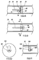
- Fig. 1 is shown the application of a CIP lining tube to an underground sewer 10.
- the tube illustrated by reference numeral 12 is being applied between manholes 14 and 16 in conventional manner which involves the use of an elbow pipe 18 in manhole 14.
- To the bottom end of the elbow pipe 18 is attached a leading end of the lining tube 12 after that leading end has been fed through the pipe 18.
- Water or other everting fluid is then poured into the pipe 18 which causes the tube 12, which is flexible although impregnated with a curable synthetic resin, to evert as shown at 20 into and along the sewer 10, so as to be applied thereto.
- the resin is caused to cure so that the lining 12 becomes a hard pipe lying on the surface of the sewer 10.
- Fig. 2 is included to illustrate the construction of the lining tube 12. It comprises a resin absorbent layer or layers 22 of felt or the like which is or are thoroughly saturated with the synthetic resin to be cured. To the inside is a membrane or film 24 which forms the means whereby the tube can be inflated, and which in the finished product forms a smooth surface enhancing flow through the cured lining.
- a membrane or film 24 which forms the means whereby the tube can be inflated, and which in the finished product forms a smooth surface enhancing flow through the cured lining.
- the application of these linings as is well known is for rehabilitation and/or repair of the sewer 10.
- thermoplastic tube 26 is winched into and along the underground pipeline 28, which may typically be a gas or water pipe, and the diameter of the pipe 26 will be slightly less than that of the pipe 28 to provide the radial clearance 30 shown in Fig. 4.
- Fig. 3 is self explanatory in illustrating how the pipe 26 is winched into pipe 28, and Fig. 4 shows that the pipe 26 contains activatable particles 32 which are polar in nature and cause the tube 26 to heat up when subjected to the radiation as described hereinafter.
- Fig. 5 illustrates one embodiment of the present invention in apparatus and in method.
- 36 represents the lining pipe when in position either as shown in Fig. 1 or in Fig. 3, and there is then pulled through the pipe in the direction of arrow 38 an apparatus comprising a magnetron 40 by which microwaves are generated, an axial wave guide 42 along which the microwave energy is supplied, and a radial wave guide 44 by which the energy is directed radially outwardly and onto the lining tube 36.
- the tube is a CIP lining tube, the resin will be heated by the action of the microwave energy, and therefore curing will commence.
- the speed of the apparatus along the lining tube in the direction of arrow 38 will be related to the speed at which the lining material cures. As shown in Fig.
- the radial wave guide 44 is made up of a pair of diametrically opposite radial arms 46 and 48 which redirect the energy radially outwardly so that it can emit energy from the ends of the arms 46 and 48 onto the lining tube 36 which arms preferably are closed by means of microwave invisible material such as PERSPEX (trade mark).
- PERSPEX microwave invisible material
- the emergent energy is caused to rotate as indicated by arrow 52.
- the entire apparatus may rotate, or it may be arranged so that the radial wave guide 44 only rotates.
- a modified radial wave guide arrangement is shown and it has four arms 54, 56, 58 and 60.
- As many arms as are required can be provided, as shown in dotted lines, and in fact instead of radial arms there may simply be a pair of spaced parallel discs forming the radial wave guide. In such latter case it may not be necessary to cause the radial wave guide to rotate but the provision of the discs still ensures the even application of the energy to the lining tube.
- An embodiment operating in this way is shown in Figs. 12 and 13.
- the apparatus shown in Fig. 5 is simply pulled along the inside of the pipeline or passageway whilst the radial wave guide is caused to rotate.
- the rate of progression of the apparatus is related to the rate of cure of the tube 36, the objective being to ensure complete and efficient cure of the entire lining tube.
- the resin matrix in the lining tube 36 when it is a CIP lining tube will be filled with particles which are activated by the applied microwave energy.
- the rapid and efficient heating up of the resin takes place, and when the resin cure commences, it will be self continuing because resin curing is exothermic and heat will be generated to continue the cure. It may therefore simply be a matter of initiating the cure using the microwave energy in which case the apparatus can move along the pipeline or passageway at a faster rate.
- thermoplastic tube contains particles such as 32 which can be activated by the microwave energy
- the apparatus and method can be used for such tubes.
- the thermoplastic tubes which are suitable to be heated by this method are inflated after softening in order to place the tubes on the pipeline to be lined. Care should be taken to ensure that the thermoplastic tubes are softened to the correct degree, because if they are not fully softened, they will when they re-cool tend to return to the original size whereas if they are heated to too great an extent, they will become too fluid to handle.
- the heating should be to the extent that the original memory is lost and a new memory in the enlarged state can be imposed.
- the axial wave guide 42 may comprise a flexible bellows construction to enable it to flex having regard to the changes in direction of the passageway in which the apparatus is used.
- a coaxial cable with a radial energy distributor (dipole) at the end thereof such as an antenna located at a suitable nodal point.
- a radial energy distributor dipole
- antenna located at a suitable nodal point.
- a parabolic mirror to focus the energy so that it is strictly radial in a particular direction, and then the parabolic mirror can be rotatable in order to apply the energy sequentially and circumferentially.
- the energy generating device 40 is shown as being inside the pipeline or passageway, it could be located at ground level, and this is especially so where the energy distributing means is a coaxial cable which extends into and along the pipeline or passageway in an axial direction and leads to a radial distributor.
- the equipment shown in Fig. 5 suitably will be winched through the pipeline or passageway, and will typically include a transformer and electrical feed cable. To facilitate its movement, the equipment may be mounted on skids, and these skids will also maintain the equipment reasonably centrally in the pipeline or passageway. Any suitable frequency of operation may be selected, but at the present the utilisation of 2.45 GHz frequency seems most appropriate.
- the lining tube With the progression of the apparatus through the lining tube, the lining will be heated progressively, and the interior of the lining in either case preferably will be held under pressure, typically air pressure up to 1 bar.
- the apparatus can indeed be used under water and water can be used for the inflation of the lining.
- the lining tubes embody particles to enable them to respond to the microwave energy
- these particles be below a size of 10 micron as the smaller particles respond more efficiently to microwave energy.
- Curie temperature ferrites can be used as the particles and they have the advantage that they will stop heating up as soon as they reach the Curie temperature.
- infra red cameras could be used.
- the energy applied by the apparatus may be controlled by using pulsed mode operation.
- Suitable mechanical mounting of rotating parts can be effected by conventional arrangements.
- the method of applying the microwave energy can be effected in various forms. In each case it is necessary that the microwave energy should be directed radially onto the lining, but this can be achieved in various ways.
- Several alternative ways are indicated in Figures 8- 11, and it should be mentioned that in relation to the embodiments of these figures, all of the features hereinbefore referred to in relation to previous figures can be employed where appropriate, and therefore further specific details of these features are not described in relation to the embodiments of Figs. 8-11. Only the essential differences are indicated.
- the radio waveguide 70 is constructed as illustrated in Figs. 5 and 6, and may be modified as described in relation to Fig. 7, and is rotatable by means of a drive motor 72 which drives through gearing 74 and 76 respectively on the motor shaft and on the waveguide 70.
- a coaxial microwave generating cable 78 does not rotate, but it penetrates centrally of the waveguide 70, and has a dipole 80 inside the waveguide which emits the microwave energy radially as indicated by the arrows 82.
- a coaxial cable 90 is used, and the dipole 92 is at the centre of the waveguide 94.
- This waveguide 94 is made up of a pair of discs, and within the waveguide is a parabolic reflector 96 which is adapted to be rotated about the dipole 92 by means of a motor 98.
- the parabolic reflector 96 focuses the microwave energy 100 (which would otherwise be distributed radially in all directions) so that a beam of the microwave energy impinges upon the lining tube 36, but that beam is progressively rotated around the circumference of the lining tube as the assembly is moved along the inside of the lining tube for the purposes hereinbefore described.
- a microwave energy source such as a magnetron 102 is arranged inside the waveguide 104 and is arranged to direct its beam of microwave energy radially as indicated by arrows 106.
- the entire waveguide and magnetron are rotated by a motor 108 to cause the progressive application of the energy 106 to the lining tube 36 in a circumferentially progressive manner.
- Figs. 12 and 13 show other arrangements according to the invention.
- the microwave apparatus is shown as being pulled through an underground sewer 200 by means of a pulling rope 202, which is connected to an eye 204 on the downstream end of the apparatus.
- the eye is coupled to the wave guide arrangement which comprises a pair of discs 206, 208 which are parallel and spaced to define the microwave energy transmission space (waveguide).
- the antenna 210 At the centre of this space is the antenna 210 which is driven by a magnetron 212 on the outside of the left hand disc 206.
- the antenna emits the energy in all radial directions and it may or may not be used with a parabolic reflector as described hereinbefore.
- the magnetron 212 is contained in an insulated casing 214 along with other electrical equipment such as a transformer 216 and a capacitor 218.
- the capacitor is coupled by means of an insulated electrical cable 220 which leads to ground level and is wound on a cable drum 224 at said ground level.
- the cable 220 is guided by means of a cable guide 226 which is supported by framework 228 on the ground surface and on the wall of the manhole 230 which leads to the underground pipe 220.
- This arrangement can be adopted where the apparatus is for curing say a length of resin impregnated tube positioned at a particular location on the surface of the pipe 200.
- the discs 206 and 208 may be mesh discs where air is used for pressurising the interior of the pipe 200 and for inflating the length of impregnated tube against the pipe 200.
- the discs 206, 208 preferably are metallic, and when they are perforated, the perforations should be designed so as not to be related to the wave length of the energy to ensure that the energy is not lost through the perforations but is concentrated at the outer periphery of the discs and is applied to the lining material.
- the perforations may be ommitted, but there may need to be connecting channels leading to the outsides of the discs, and bridging the wave guide to allow the water to pass from one side of the wave guide to the other to eliminate the discs acting with a piston effect.
- edges of the discs preferably are flexible so as to accommodate variations in pipe shape, step joints and pipe intrusions such as root and lateral pipe intrusions.
- the sealing effect at the periphery of the discs may require to be more effective.
- the appropriate power supply connecting through cable 220 will be provided, and this power supply can be varied by adopting a pulsed power supply arrangement.
- the intention is that the power should be coupled to the magnetron to give a microwave emission or frequency in the order of 2.45 GHz.
- Fig. 13 basically shows the arrangement of Fig. 12, but when used in connection with a CIP lining which is being everted into the passageway 200 in a manner similar to that illustrated in Fig. 1. Also, the cable guide 226 is omitted, as the elbow pipe 18 will in conventional manner form the cable guide. The top of the pipe 18 may be sealed by means of a split cover 232, 234, so that the inflating pressure can be maintained (when air is used) but otherwise the arrangement of Fig. 13 is identical to that of Fig. 12, and similar reference numerals have been used.
- the apparatus can incorporate a device for deflecting any reflected waves and providing a means to absorb such reflected waves in order to avoid the reflected waves being returned to the magnetron, which could damage the magnetron.
- a device for deflecting any reflected waves and providing a means to absorb such reflected waves in order to avoid the reflected waves being returned to the magnetron, which could damage the magnetron.
- Such deflecting devices are well known and indeed are invisible to the emitted energy but deflect the reflected energy.
Landscapes
- Engineering & Computer Science (AREA)
- Health & Medical Sciences (AREA)
- Thermal Sciences (AREA)
- Physics & Mathematics (AREA)
- General Engineering & Computer Science (AREA)
- Manufacturing & Machinery (AREA)
- Mechanical Engineering (AREA)
- Toxicology (AREA)
- Oral & Maxillofacial Surgery (AREA)
- Lining Or Joining Of Plastics Or The Like (AREA)
- Application Of Or Painting With Fluid Materials (AREA)
- Rigid Pipes And Flexible Pipes (AREA)
- Pipe Accessories (AREA)
- Protection Of Pipes Against Damage, Friction, And Corrosion (AREA)
Claims (18)
- Verfahren zum Auskleiden einer Pipeline oder eines Kanals (10, 28), bei dem durch eine in der Pipeline oder in dem Kanal positionierte Futtertube (36) eine Vorrichtung (40, 44) geführt wird, und die Vorrichtung Mikrowellenenergie radial auf die Innenseite der Futtertube (36) gerichtet aufbringt, und die Futtertube auf eine von zwei Weisen für diese Energie empfindlich ist, nämlich (i) sie enthält einen aushärtbaren Harz, der durch das Aufbringen der Energie aushärtet, oder (ii) sie ist thermoplastisch und enthält ein partikelförmiges Polarmaterial (32), das aufgrund der Einwirkung der Mikrowellenenergie erhitzt wird, so daß die Tube (10) erweicht und sich ausdehnen kann, dadurch gekennzeichnet, daß die Mikrowellenenergie die Form von einem oder mehreren radialen Strömen (100) hat, die um die Achse der Pipeline oder des Kanals (10, 28) rotieren, während die Vorrichtung durch die Futtertube (10, 28) geführt wird.
- Verfahren nach Anspruch 1, bei dem der/die genannte(n) ein oder mehreren radialen Ströme (100) durch Rotation eines Hohlleiters (44) gedreht wird/werden, durch den der Strom bzw. die Ströme (100) passiert/passieren.
- Verfahren nach Anspruch 1 oder 2, bei dem die Energieerzeugungsquelle (102) Teil der Vorrichtung ist, so angeordnet ist, daß ein Strom (100) von Mikrowellenenergie radial gerichtet wird, und um die Achse der Pipeline oder des Kanals (10, 28) gedreht wird.
- Verfahren nach einem der Ansprüche 1 bis 3, bei dem die Energie durch ein Koaxialkabel (78) zu einem Dipol (80) gespeist wird, der so angeordnet ist, daß er die Energie radial zur Pipeline oder zum Kanal (10, 28) ausstrahlt.
- Verfahren nach Anspruch 4, bei dem die Energie durch einen Spiegel (96) zu einem Strahl (100) gebündelt wird und der Spiegel (96) drehbar ist, um zu bewirken, daß der Strahl (100) periphär zur Futtertube (36) rotiert.
- Vorrichtung zum Durchführen des Verfahrens von Anspruch 1, umfassend eine Mikrowellenenergiequelle (40), einen Hohlleiter (44) zum Richten von Energie von der Quelle (40) radial in die Futtertube (36), und ein Mittel, um das Fortschreiten der radial gerichteten Energie (100) umfangsmäßig zur Futtertube (36) zu bewirken.
- Vorrichtung nach Anspruch 6, bei der der genannte Hohlleiter (44) relativ zur Mikrowellenenergiequelle (40) drehbar ist, um das genannte umfangsmäßige Fortschreiten zu bewirken.
- Vorrichtung nach Anspruch 7, bei der die Mikrowellenenergiequelle (40) relativ zum Hohlleiter (44) fest ist.
- Vorrichtung nach Anspruch 8, bei der die Mikrowellenenergiequelle (40) zur Rotation mit dem Hohlleiter (44) montiert ist.
- Vorrichtung nach Anspruch 9, bei der die Energiequelle einen Dipol (92) am Ende eines Koaxialkabels (78) beinhaltet.
- Vorrichtung nach Anspruch 10, bei der ein Parabolspiegel (96) angeordnet ist, um die Energie von dem Dipol (92) zu einem Radialstrahl (100) zu bündeln.
- Vorrichtung nach Anspruch 11, bei der der Hohlleiter beabstandete Scheiben (206, 208) umfaßt und der Spiegel (96) um den Dipol (210) gedreht wird.
- Vorrichtung nach einem der vorherigen Ansprüche 6 bis 11, bei der der Hohlleiter (44) die Form von einem oder mehreren Armen (46, 48, 54, 56, 58, 60) hat.
- Vorrichtung zum Aufbringen von Mikrowellenenergie auf eine Auskleidung einer Pipeline oder eines Kanals nach dem Verfahren von Anspruch 1, umfassend eine Mikrowellenenergiequelle (212), einen Hohlleiter (206, 208) zum Richten von Energie von der Quelle (212) radial in die Futtertube (36), wobei der genannte Hohlleiter (206, 208) ein Paar beabstandeter Scheiben (206, 208) aufweist, die mit ihren Ebenen quer zur Achse der Pipeline oder des Kanals (10, 28) liegen.
- Vorrichtung nach Anspruch 14, bei der die Scheiben (206, 208) Dichtungselemente an ihrem Umfang aufweisen, um gegen die Pipeline- oder Kanaloberfläche abzudichten.
- Vorrichtung nach Anspruch 14 oder 15, bei der die Mikrowellenenergiequelle (212) eine Antenne (210) in der Mitte des Hohlleiters (206, 208) umfaßt.
- Vorrichtung nach Anspruch 16, bei der die Energiequelle (212) ein Magnetron (212) umfaßt, das an die Antenne (210) angeschlossen ist, sich aber außerhalb des Hohlleiters (206, 208) befindet.
- Vorrichtung nach Anspruch 17, bei der das Magnetron (212) in einem isolierten Kanister (214) zusammen mit anderen elektrischen Komponenten (218) enthalten ist, um den benötigten Ausgang von dem Magnetron (212) bereitzustellen, und der Kanister (214) entlang der Pipeline oder des Kanals (10, 28) mit dem Hohlleiter (206, 208) bewegt und Strom durch ein Stromkabel (220) zugeführt wird.
Applications Claiming Priority (5)
| Application Number | Priority Date | Filing Date | Title |
|---|---|---|---|
| GB9421369A GB9421369D0 (en) | 1994-10-24 | 1994-10-24 | Improvements relating to lining of pipelines and passageways |
| GB9421369 | 1994-10-24 | ||
| GB9500739 | 1995-01-14 | ||
| GBGB9500739.9A GB9500739D0 (en) | 1995-01-14 | 1995-01-14 | Improvements relating to lining of pipelines and passageways |
| PCT/GB1995/002328 WO1996012605A1 (en) | 1994-10-24 | 1995-10-02 | Improvements relating to lining of pipelines and passageways |
Publications (2)
| Publication Number | Publication Date |
|---|---|
| EP0788423A1 EP0788423A1 (de) | 1997-08-13 |
| EP0788423B1 true EP0788423B1 (de) | 1998-08-05 |
Family
ID=26305857
Family Applications (1)
| Application Number | Title | Priority Date | Filing Date |
|---|---|---|---|
| EP95932847A Expired - Lifetime EP0788423B1 (de) | 1994-10-24 | 1995-10-02 | Verbesserungen in bezug auf die auskleidung von rohrleitungen und durchgängen |
Country Status (7)
| Country | Link |
|---|---|
| EP (1) | EP0788423B1 (de) |
| AT (1) | ATE169263T1 (de) |
| AU (1) | AU3573395A (de) |
| DE (1) | DE69503917T2 (de) |
| DK (1) | DK0788423T3 (de) |
| ES (1) | ES2122679T3 (de) |
| WO (1) | WO1996012605A1 (de) |
Cited By (2)
| Publication number | Priority date | Publication date | Assignee | Title |
|---|---|---|---|---|
| DE10049101C1 (de) * | 2000-09-27 | 2002-04-04 | Karlsruhe Forschzent | Mobile Aushärtvorrichtung zur Aushärtung der an sanierten Kanalabschnitten/-stellen aufgebrachten Abdicht- und Verbindungsmittel mittels Mikrowelle |
| WO2018145863A1 (de) * | 2017-02-10 | 2018-08-16 | Trelleborg Pipe Seals Duisburg Gmbh | Sanierungsvorrichtung zur sanierung einer rohrleitung, harzsystem zur tränkung eines auskleidungselements zur sanierung einer rohrleitung und verfahren zum auskleiden einer rohrleitung |
Families Citing this family (5)
| Publication number | Priority date | Publication date | Assignee | Title |
|---|---|---|---|---|
| WO2007079542A1 (en) * | 2006-01-13 | 2007-07-19 | Brisbane City Council | Method and apparatus for treating roots in and around a conduit |
| EP2029664A4 (de) * | 2006-05-31 | 2015-09-09 | Dow Global Technologies Llc | Additive für die verwendung von mikrowellenenergie zum selektiven erhitzen von thermoplastischen polymersystemen |
| US8328969B2 (en) | 2011-01-04 | 2012-12-11 | Gearhart Stephen V | Method and system for curing pipe liners using microwave energy |
| GB2527821B (en) * | 2014-07-03 | 2017-05-03 | Craley Group Ltd | Improvements in or in relation to pipe liners and the installation thereof |
| EP3839320A1 (de) * | 2019-12-18 | 2021-06-23 | Bodus GmbH | System zum aushärten und/oder überprüfen einer rohrleitungsauskleidung und verfahren zum aushärten und/oder überprüfen einer rohrleitungsauskleidung |
Family Cites Families (5)
| Publication number | Priority date | Publication date | Assignee | Title |
|---|---|---|---|---|
| GB8608805D0 (en) * | 1986-04-11 | 1986-05-14 | Du Pont Uk | Thermoplastic polymer-lined pipe |
| CH676493A5 (en) * | 1986-12-30 | 1991-01-31 | Ferenz Szabo | Refurbishing underground pipes - by drawing through existing pipe two-ply plastic film with hard-setting resin core, inflating to size and hard setting resin |
| DE3732694C2 (de) * | 1987-09-29 | 1994-02-24 | Roland Herr | Verfahren zum Auskleiden von Kanälen |
| SE9100870D0 (sv) * | 1991-03-22 | 1991-03-22 | Inpipe Sweden Ab | Foerfarande och anordning foer infodring av en helt eller delvis vaeggomsluten passage |
| DE4205113C1 (en) * | 1992-02-20 | 1993-04-29 | Softlining Ag Systems For Relining, Thun, Ch | Radiation source for irradiating inner walls of long hollow chambers - has framework contg. central, carrier in which 1st set of lamps are arranged equidistantly and 2nd set are displaced w.r.t. 1st set |
-
1995
- 1995-10-02 WO PCT/GB1995/002328 patent/WO1996012605A1/en active IP Right Grant
- 1995-10-02 DE DE69503917T patent/DE69503917T2/de not_active Expired - Fee Related
- 1995-10-02 ES ES95932847T patent/ES2122679T3/es not_active Expired - Lifetime
- 1995-10-02 DK DK95932847T patent/DK0788423T3/da active
- 1995-10-02 EP EP95932847A patent/EP0788423B1/de not_active Expired - Lifetime
- 1995-10-02 AT AT95932847T patent/ATE169263T1/de not_active IP Right Cessation
- 1995-10-02 AU AU35733/95A patent/AU3573395A/en not_active Abandoned
Cited By (2)
| Publication number | Priority date | Publication date | Assignee | Title |
|---|---|---|---|---|
| DE10049101C1 (de) * | 2000-09-27 | 2002-04-04 | Karlsruhe Forschzent | Mobile Aushärtvorrichtung zur Aushärtung der an sanierten Kanalabschnitten/-stellen aufgebrachten Abdicht- und Verbindungsmittel mittels Mikrowelle |
| WO2018145863A1 (de) * | 2017-02-10 | 2018-08-16 | Trelleborg Pipe Seals Duisburg Gmbh | Sanierungsvorrichtung zur sanierung einer rohrleitung, harzsystem zur tränkung eines auskleidungselements zur sanierung einer rohrleitung und verfahren zum auskleiden einer rohrleitung |
Also Published As
| Publication number | Publication date |
|---|---|
| AU3573395A (en) | 1996-05-15 |
| DE69503917D1 (de) | 1998-09-10 |
| WO1996012605A1 (en) | 1996-05-02 |
| EP0788423A1 (de) | 1997-08-13 |
| ES2122679T3 (es) | 1998-12-16 |
| ATE169263T1 (de) | 1998-08-15 |
| DE69503917T2 (de) | 1999-01-14 |
| DK0788423T3 (da) | 1998-11-16 |
Similar Documents
| Publication | Publication Date | Title |
|---|---|---|
| US5634743A (en) | Lining of pipelines and passageways | |
| US5927341A (en) | Lining of "Tees" and "Wyes" in pipelines or passageways | |
| WO1993015131A2 (en) | Curable resin systems and applications thereof | |
| EP0788423B1 (de) | Verbesserungen in bezug auf die auskleidung von rohrleitungen und durchgängen | |
| JPS60242038A (ja) | パイプラインおよび通路の内張法 | |
| AU671197B2 (en) | Improvements relating to the lining of pipelines and passageways | |
| KR19990068142A (ko) | 관라이닝 공법 | |
| RU2352852C2 (ru) | Отверждаемый на месте облицовочный материал с внешним непроницаемым слоем и способ его изготовления | |
| CA2030791A1 (en) | Apparatus for refurbishing pipelines and sewer pipes through the application of a lining to their inner walls | |
| JPH08512251A (ja) | パイプラインや通路のライニング | |
| EP0707531B1 (de) | Anbringen von auskleidungen in pipelines und leitungen | |
| WO1992020504A1 (en) | Ultrasonically cured replacement pipe and method of installation | |
| US6302983B1 (en) | Method for lining underground pipelines | |
| CA2291821A1 (en) | Apparatus and method for lining of passageways | |
| RU98115004A (ru) | Способ облицовки подземных трубопроводов | |
| RU2145029C1 (ru) | Способ облицовки трубопровода | |
| JPH11294684A (ja) | 光硬化式管路内面補修方法および装置 | |
| WO1998051960A1 (en) | Improvements relating to curing of synthetic resin systems, for example, in the lining of pipelines and passageways | |
| EP0832390A1 (de) | Verbesserungen in bezug auf die auskleidung von rohrleitungen und kanälen | |
| CA2242098A1 (en) | Method for lining underground pipelines | |
| WO1995025002A1 (en) | Improvements relating to the lining of pipelines and passageways | |
| JP3691883B2 (ja) | 既設管路の補修工法 | |
| EP0856694A1 (de) | Verfahren zur Verlegung von Rohren wobei ein platter Schlauch mit Flüssigkeit, vorzugweise Wasser, gefüllt wird | |
| JPH11230476A (ja) | 可視光硬化式管路内面補修方法および装置 | |
| US20240280206A1 (en) | Assembly and method for repairing pipe having more complete liner expansion |
Legal Events
| Date | Code | Title | Description |
|---|---|---|---|
| PUAI | Public reference made under article 153(3) epc to a published international application that has entered the european phase |
Free format text: ORIGINAL CODE: 0009012 |
|
| 17P | Request for examination filed |
Effective date: 19970414 |
|
| AK | Designated contracting states |
Kind code of ref document: A1 Designated state(s): AT BE CH DE DK ES FR GB GR IE IT LI LU MC NL PT SE |
|
| AX | Request for extension of the european patent |
Free format text: LT PAYMENT 970414;LV PAYMENT 970414;SI PAYMENT 970414 |
|
| GRAG | Despatch of communication of intention to grant |
Free format text: ORIGINAL CODE: EPIDOS AGRA |
|
| 17Q | First examination report despatched |
Effective date: 19971112 |
|
| GRAG | Despatch of communication of intention to grant |
Free format text: ORIGINAL CODE: EPIDOS AGRA |
|
| GRAH | Despatch of communication of intention to grant a patent |
Free format text: ORIGINAL CODE: EPIDOS IGRA |
|
| GRAH | Despatch of communication of intention to grant a patent |
Free format text: ORIGINAL CODE: EPIDOS IGRA |
|
| GRAA | (expected) grant |
Free format text: ORIGINAL CODE: 0009210 |
|
| AK | Designated contracting states |
Kind code of ref document: B1 Designated state(s): AT BE CH DE DK ES FR GB GR IE IT LI LU MC NL PT SE |
|
| AX | Request for extension of the european patent |
Free format text: LT PAYMENT 970414;LV PAYMENT 970414;SI PAYMENT 970414 |
|
| LTIE | Lt: invalidation of european patent or patent extension | ||
| PG25 | Lapsed in a contracting state [announced via postgrant information from national office to epo] |
Ref country code: IT Free format text: LAPSE BECAUSE OF FAILURE TO SUBMIT A TRANSLATION OF THE DESCRIPTION OR TO PAY THE FEE WITHIN THE PRE;WARNING: LAPSES OF ITALIAN PATENTS WITH EFFECTIVE DATE BEFORE 2007 MAY HAVE OCCURRED AT ANY TIME BEFORE 2007. THE CORRECT EFFECTIVE DATE MAY BE DIFFERENT FROM THE ONE RECORDED.SCRIBED TIME-LIMIT Effective date: 19980805 Ref country code: GR Free format text: LAPSE BECAUSE OF FAILURE TO SUBMIT A TRANSLATION OF THE DESCRIPTION OR TO PAY THE FEE WITHIN THE PRESCRIBED TIME-LIMIT Effective date: 19980805 Ref country code: BE Free format text: LAPSE BECAUSE OF FAILURE TO SUBMIT A TRANSLATION OF THE DESCRIPTION OR TO PAY THE FEE WITHIN THE PRESCRIBED TIME-LIMIT Effective date: 19980805 Ref country code: AT Free format text: LAPSE BECAUSE OF FAILURE TO SUBMIT A TRANSLATION OF THE DESCRIPTION OR TO PAY THE FEE WITHIN THE PRESCRIBED TIME-LIMIT Effective date: 19980805 |
|
| REF | Corresponds to: |
Ref document number: 169263 Country of ref document: AT Date of ref document: 19980815 Kind code of ref document: T |
|
| REG | Reference to a national code |
Ref country code: CH Ref legal event code: NV Representative=s name: ABREMA AGENCE BREVETS ET MARQUES GANGUILLET & HUMP Ref country code: CH Ref legal event code: EP |
|
| REF | Corresponds to: |
Ref document number: 69503917 Country of ref document: DE Date of ref document: 19980910 |
|
| PG25 | Lapsed in a contracting state [announced via postgrant information from national office to epo] |
Ref country code: LU Free format text: LAPSE BECAUSE OF NON-PAYMENT OF DUE FEES Effective date: 19981002 Ref country code: DK Free format text: LAPSE BECAUSE OF NON-PAYMENT OF DUE FEES Effective date: 19981002 |
|
| PG25 | Lapsed in a contracting state [announced via postgrant information from national office to epo] |
Ref country code: IE Free format text: LAPSE BECAUSE OF NON-PAYMENT OF DUE FEES Effective date: 19981005 |
|
| ET | Fr: translation filed | ||
| REG | Reference to a national code |
Ref country code: IE Ref legal event code: FG4D |
|
| PG25 | Lapsed in a contracting state [announced via postgrant information from national office to epo] |
Ref country code: SE Free format text: LAPSE BECAUSE OF FAILURE TO SUBMIT A TRANSLATION OF THE DESCRIPTION OR TO PAY THE FEE WITHIN THE PRESCRIBED TIME-LIMIT Effective date: 19981105 Ref country code: PT Free format text: LAPSE BECAUSE OF FAILURE TO SUBMIT A TRANSLATION OF THE DESCRIPTION OR TO PAY THE FEE WITHIN THE PRESCRIBED TIME-LIMIT Effective date: 19981105 |
|
| PGFP | Annual fee paid to national office [announced via postgrant information from national office to epo] |
Ref country code: ES Payment date: 19981109 Year of fee payment: 4 |
|
| REG | Reference to a national code |
Ref country code: DK Ref legal event code: T3 |
|
| REG | Reference to a national code |
Ref country code: ES Ref legal event code: FG2A Ref document number: 2122679 Country of ref document: ES Kind code of ref document: T3 |
|
| PG25 | Lapsed in a contracting state [announced via postgrant information from national office to epo] |
Ref country code: MC Free format text: LAPSE BECAUSE OF NON-PAYMENT OF DUE FEES Effective date: 19990430 |
|
| PLBE | No opposition filed within time limit |
Free format text: ORIGINAL CODE: 0009261 |
|
| STAA | Information on the status of an ep patent application or granted ep patent |
Free format text: STATUS: NO OPPOSITION FILED WITHIN TIME LIMIT |
|
| PG25 | Lapsed in a contracting state [announced via postgrant information from national office to epo] |
Ref country code: FR Free format text: LAPSE BECAUSE OF NON-PAYMENT OF DUE FEES Effective date: 19990630 |
|
| 26N | No opposition filed | ||
| REG | Reference to a national code |
Ref country code: IE Ref legal event code: MM4A |
|
| REG | Reference to a national code |
Ref country code: FR Ref legal event code: ST |
|
| PG25 | Lapsed in a contracting state [announced via postgrant information from national office to epo] |
Ref country code: DE Free format text: LAPSE BECAUSE OF NON-PAYMENT OF DUE FEES Effective date: 19990803 |
|
| PG25 | Lapsed in a contracting state [announced via postgrant information from national office to epo] |
Ref country code: GB Free format text: LAPSE BECAUSE OF NON-PAYMENT OF DUE FEES Effective date: 19991002 |
|
| PG25 | Lapsed in a contracting state [announced via postgrant information from national office to epo] |
Ref country code: ES Free format text: LAPSE BECAUSE OF NON-PAYMENT OF DUE FEES Effective date: 19991003 |
|
| PG25 | Lapsed in a contracting state [announced via postgrant information from national office to epo] |
Ref country code: LI Free format text: LAPSE BECAUSE OF NON-PAYMENT OF DUE FEES Effective date: 19991031 Ref country code: CH Free format text: LAPSE BECAUSE OF NON-PAYMENT OF DUE FEES Effective date: 19991031 |
|
| PG25 | Lapsed in a contracting state [announced via postgrant information from national office to epo] |
Ref country code: NL Free format text: LAPSE BECAUSE OF NON-PAYMENT OF DUE FEES Effective date: 20000501 |
|
| GBPC | Gb: european patent ceased through non-payment of renewal fee |
Effective date: 19991002 |
|
| REG | Reference to a national code |
Ref country code: CH Ref legal event code: PL |
|
| NLV4 | Nl: lapsed or anulled due to non-payment of the annual fee |
Effective date: 20000501 |
|
| REG | Reference to a national code |
Ref country code: DK Ref legal event code: EBP |
|
| REG | Reference to a national code |
Ref country code: ES Ref legal event code: FD2A Effective date: 20001113 |