EP0788282B1 - Quantization method - Google Patents
Quantization method Download PDFInfo
- Publication number
- EP0788282B1 EP0788282B1 EP97101782A EP97101782A EP0788282B1 EP 0788282 B1 EP0788282 B1 EP 0788282B1 EP 97101782 A EP97101782 A EP 97101782A EP 97101782 A EP97101782 A EP 97101782A EP 0788282 B1 EP0788282 B1 EP 0788282B1
- Authority
- EP
- European Patent Office
- Prior art keywords
- value
- quantization
- linear
- input
- predictive
- Prior art date
- Legal status (The legal status is an assumption and is not a legal conclusion. Google has not performed a legal analysis and makes no representation as to the accuracy of the status listed.)
- Expired - Lifetime
Links
- 238000013139 quantization Methods 0.000 title claims description 504
- 238000000034 method Methods 0.000 title description 11
- 230000001172 regenerating effect Effects 0.000 claims description 69
- 238000012545 processing Methods 0.000 description 56
- 238000010276 construction Methods 0.000 description 37
- 238000010586 diagram Methods 0.000 description 24
- 238000012937 correction Methods 0.000 description 18
- 230000002093 peripheral effect Effects 0.000 description 13
- 230000006835 compression Effects 0.000 description 6
- 238000007906 compression Methods 0.000 description 6
- 230000000694 effects Effects 0.000 description 5
- 230000007423 decrease Effects 0.000 description 4
- 230000008901 benefit Effects 0.000 description 3
- 230000001174 ascending effect Effects 0.000 description 2
- 230000008859 change Effects 0.000 description 2
- 238000006243 chemical reaction Methods 0.000 description 2
- 238000011161 development Methods 0.000 description 2
- 230000018109 developmental process Effects 0.000 description 2
- 238000003780 insertion Methods 0.000 description 2
- 230000037431 insertion Effects 0.000 description 2
- 238000012986 modification Methods 0.000 description 2
- 230000004048 modification Effects 0.000 description 2
- 230000000644 propagated effect Effects 0.000 description 2
- 230000009467 reduction Effects 0.000 description 2
- 230000005540 biological transmission Effects 0.000 description 1
- 238000007429 general method Methods 0.000 description 1
- 238000001454 recorded image Methods 0.000 description 1
- 238000011084 recovery Methods 0.000 description 1
- 230000008929 regeneration Effects 0.000 description 1
- 238000011069 regeneration method Methods 0.000 description 1
Images













Classifications
-
- H—ELECTRICITY
- H04—ELECTRIC COMMUNICATION TECHNIQUE
- H04N—PICTORIAL COMMUNICATION, e.g. TELEVISION
- H04N9/00—Details of colour television systems
- H04N9/79—Processing of colour television signals in connection with recording
- H04N9/80—Transformation of the television signal for recording, e.g. modulation, frequency changing; Inverse transformation for playback
- H04N9/82—Transformation of the television signal for recording, e.g. modulation, frequency changing; Inverse transformation for playback the individual colour picture signal components being recorded simultaneously only
- H04N9/8205—Transformation of the television signal for recording, e.g. modulation, frequency changing; Inverse transformation for playback the individual colour picture signal components being recorded simultaneously only involving the multiplexing of an additional signal and the colour video signal
-
- H—ELECTRICITY
- H04—ELECTRIC COMMUNICATION TECHNIQUE
- H04N—PICTORIAL COMMUNICATION, e.g. TELEVISION
- H04N19/00—Methods or arrangements for coding, decoding, compressing or decompressing digital video signals
- H04N19/10—Methods or arrangements for coding, decoding, compressing or decompressing digital video signals using adaptive coding
- H04N19/102—Methods or arrangements for coding, decoding, compressing or decompressing digital video signals using adaptive coding characterised by the element, parameter or selection affected or controlled by the adaptive coding
- H04N19/124—Quantisation
-
- H—ELECTRICITY
- H04—ELECTRIC COMMUNICATION TECHNIQUE
- H04N—PICTORIAL COMMUNICATION, e.g. TELEVISION
- H04N19/00—Methods or arrangements for coding, decoding, compressing or decompressing digital video signals
- H04N19/10—Methods or arrangements for coding, decoding, compressing or decompressing digital video signals using adaptive coding
- H04N19/169—Methods or arrangements for coding, decoding, compressing or decompressing digital video signals using adaptive coding characterised by the coding unit, i.e. the structural portion or semantic portion of the video signal being the object or the subject of the adaptive coding
- H04N19/186—Methods or arrangements for coding, decoding, compressing or decompressing digital video signals using adaptive coding characterised by the coding unit, i.e. the structural portion or semantic portion of the video signal being the object or the subject of the adaptive coding the unit being a colour or a chrominance component
-
- H—ELECTRICITY
- H04—ELECTRIC COMMUNICATION TECHNIQUE
- H04N—PICTORIAL COMMUNICATION, e.g. TELEVISION
- H04N19/00—Methods or arrangements for coding, decoding, compressing or decompressing digital video signals
- H04N19/46—Embedding additional information in the video signal during the compression process
-
- H—ELECTRICITY
- H04—ELECTRIC COMMUNICATION TECHNIQUE
- H04N—PICTORIAL COMMUNICATION, e.g. TELEVISION
- H04N19/00—Methods or arrangements for coding, decoding, compressing or decompressing digital video signals
- H04N19/46—Embedding additional information in the video signal during the compression process
- H04N19/467—Embedding additional information in the video signal during the compression process characterised by the embedded information being invisible, e.g. watermarking
-
- H—ELECTRICITY
- H04—ELECTRIC COMMUNICATION TECHNIQUE
- H04N—PICTORIAL COMMUNICATION, e.g. TELEVISION
- H04N19/00—Methods or arrangements for coding, decoding, compressing or decompressing digital video signals
- H04N19/50—Methods or arrangements for coding, decoding, compressing or decompressing digital video signals using predictive coding
-
- H—ELECTRICITY
- H04—ELECTRIC COMMUNICATION TECHNIQUE
- H04N—PICTORIAL COMMUNICATION, e.g. TELEVISION
- H04N19/00—Methods or arrangements for coding, decoding, compressing or decompressing digital video signals
- H04N19/50—Methods or arrangements for coding, decoding, compressing or decompressing digital video signals using predictive coding
- H04N19/593—Methods or arrangements for coding, decoding, compressing or decompressing digital video signals using predictive coding involving spatial prediction techniques
-
- H—ELECTRICITY
- H04—ELECTRIC COMMUNICATION TECHNIQUE
- H04N—PICTORIAL COMMUNICATION, e.g. TELEVISION
- H04N19/00—Methods or arrangements for coding, decoding, compressing or decompressing digital video signals
- H04N19/60—Methods or arrangements for coding, decoding, compressing or decompressing digital video signals using transform coding
-
- H—ELECTRICITY
- H04—ELECTRIC COMMUNICATION TECHNIQUE
- H04N—PICTORIAL COMMUNICATION, e.g. TELEVISION
- H04N19/00—Methods or arrangements for coding, decoding, compressing or decompressing digital video signals
- H04N19/90—Methods or arrangements for coding, decoding, compressing or decompressing digital video signals using coding techniques not provided for in groups H04N19/10-H04N19/85, e.g. fractals
- H04N19/91—Entropy coding, e.g. variable length coding [VLC] or arithmetic coding
-
- H—ELECTRICITY
- H04—ELECTRIC COMMUNICATION TECHNIQUE
- H04N—PICTORIAL COMMUNICATION, e.g. TELEVISION
- H04N21/00—Selective content distribution, e.g. interactive television or video on demand [VOD]
- H04N21/20—Servers specifically adapted for the distribution of content, e.g. VOD servers; Operations thereof
- H04N21/23—Processing of content or additional data; Elementary server operations; Server middleware
- H04N21/234—Processing of video elementary streams, e.g. splicing of video streams or manipulating encoded video stream scene graphs
- H04N21/2343—Processing of video elementary streams, e.g. splicing of video streams or manipulating encoded video stream scene graphs involving reformatting operations of video signals for distribution or compliance with end-user requests or end-user device requirements
-
- H—ELECTRICITY
- H04—ELECTRIC COMMUNICATION TECHNIQUE
- H04N—PICTORIAL COMMUNICATION, e.g. TELEVISION
- H04N21/00—Selective content distribution, e.g. interactive television or video on demand [VOD]
- H04N21/20—Servers specifically adapted for the distribution of content, e.g. VOD servers; Operations thereof
- H04N21/23—Processing of content or additional data; Elementary server operations; Server middleware
- H04N21/235—Processing of additional data, e.g. scrambling of additional data or processing content descriptors
-
- H—ELECTRICITY
- H04—ELECTRIC COMMUNICATION TECHNIQUE
- H04N—PICTORIAL COMMUNICATION, e.g. TELEVISION
- H04N21/00—Selective content distribution, e.g. interactive television or video on demand [VOD]
- H04N21/20—Servers specifically adapted for the distribution of content, e.g. VOD servers; Operations thereof
- H04N21/23—Processing of content or additional data; Elementary server operations; Server middleware
- H04N21/235—Processing of additional data, e.g. scrambling of additional data or processing content descriptors
- H04N21/2353—Processing of additional data, e.g. scrambling of additional data or processing content descriptors specifically adapted to content descriptors, e.g. coding, compressing or processing of metadata
-
- H—ELECTRICITY
- H04—ELECTRIC COMMUNICATION TECHNIQUE
- H04N—PICTORIAL COMMUNICATION, e.g. TELEVISION
- H04N21/00—Selective content distribution, e.g. interactive television or video on demand [VOD]
- H04N21/20—Servers specifically adapted for the distribution of content, e.g. VOD servers; Operations thereof
- H04N21/23—Processing of content or additional data; Elementary server operations; Server middleware
- H04N21/236—Assembling of a multiplex stream, e.g. transport stream, by combining a video stream with other content or additional data, e.g. inserting a URL [Uniform Resource Locator] into a video stream, multiplexing software data into a video stream; Remultiplexing of multiplex streams; Insertion of stuffing bits into the multiplex stream, e.g. to obtain a constant bit-rate; Assembling of a packetised elementary stream
-
- H—ELECTRICITY
- H04—ELECTRIC COMMUNICATION TECHNIQUE
- H04N—PICTORIAL COMMUNICATION, e.g. TELEVISION
- H04N21/00—Selective content distribution, e.g. interactive television or video on demand [VOD]
- H04N21/20—Servers specifically adapted for the distribution of content, e.g. VOD servers; Operations thereof
- H04N21/23—Processing of content or additional data; Elementary server operations; Server middleware
- H04N21/236—Assembling of a multiplex stream, e.g. transport stream, by combining a video stream with other content or additional data, e.g. inserting a URL [Uniform Resource Locator] into a video stream, multiplexing software data into a video stream; Remultiplexing of multiplex streams; Insertion of stuffing bits into the multiplex stream, e.g. to obtain a constant bit-rate; Assembling of a packetised elementary stream
- H04N21/23614—Multiplexing of additional data and video streams
-
- H—ELECTRICITY
- H04—ELECTRIC COMMUNICATION TECHNIQUE
- H04N—PICTORIAL COMMUNICATION, e.g. TELEVISION
- H04N21/00—Selective content distribution, e.g. interactive television or video on demand [VOD]
- H04N21/40—Client devices specifically adapted for the reception of or interaction with content, e.g. set-top-box [STB]; Operations thereof
- H04N21/41—Structure of client; Structure of client peripherals
- H04N21/414—Specialised client platforms, e.g. receiver in car or embedded in a mobile appliance
- H04N21/4147—PVR [Personal Video Recorder]
-
- H—ELECTRICITY
- H04—ELECTRIC COMMUNICATION TECHNIQUE
- H04N—PICTORIAL COMMUNICATION, e.g. TELEVISION
- H04N21/00—Selective content distribution, e.g. interactive television or video on demand [VOD]
- H04N21/40—Client devices specifically adapted for the reception of or interaction with content, e.g. set-top-box [STB]; Operations thereof
- H04N21/43—Processing of content or additional data, e.g. demultiplexing additional data from a digital video stream; Elementary client operations, e.g. monitoring of home network or synchronising decoder's clock; Client middleware
- H04N21/433—Content storage operation, e.g. storage operation in response to a pause request, caching operations
- H04N21/4334—Recording operations
-
- H—ELECTRICITY
- H04—ELECTRIC COMMUNICATION TECHNIQUE
- H04N—PICTORIAL COMMUNICATION, e.g. TELEVISION
- H04N21/00—Selective content distribution, e.g. interactive television or video on demand [VOD]
- H04N21/40—Client devices specifically adapted for the reception of or interaction with content, e.g. set-top-box [STB]; Operations thereof
- H04N21/43—Processing of content or additional data, e.g. demultiplexing additional data from a digital video stream; Elementary client operations, e.g. monitoring of home network or synchronising decoder's clock; Client middleware
- H04N21/434—Disassembling of a multiplex stream, e.g. demultiplexing audio and video streams, extraction of additional data from a video stream; Remultiplexing of multiplex streams; Extraction or processing of SI; Disassembling of packetised elementary stream
-
- H—ELECTRICITY
- H04—ELECTRIC COMMUNICATION TECHNIQUE
- H04N—PICTORIAL COMMUNICATION, e.g. TELEVISION
- H04N21/00—Selective content distribution, e.g. interactive television or video on demand [VOD]
- H04N21/40—Client devices specifically adapted for the reception of or interaction with content, e.g. set-top-box [STB]; Operations thereof
- H04N21/43—Processing of content or additional data, e.g. demultiplexing additional data from a digital video stream; Elementary client operations, e.g. monitoring of home network or synchronising decoder's clock; Client middleware
- H04N21/434—Disassembling of a multiplex stream, e.g. demultiplexing audio and video streams, extraction of additional data from a video stream; Remultiplexing of multiplex streams; Extraction or processing of SI; Disassembling of packetised elementary stream
- H04N21/4348—Demultiplexing of additional data and video streams
-
- H—ELECTRICITY
- H04—ELECTRIC COMMUNICATION TECHNIQUE
- H04N—PICTORIAL COMMUNICATION, e.g. TELEVISION
- H04N21/00—Selective content distribution, e.g. interactive television or video on demand [VOD]
- H04N21/40—Client devices specifically adapted for the reception of or interaction with content, e.g. set-top-box [STB]; Operations thereof
- H04N21/43—Processing of content or additional data, e.g. demultiplexing additional data from a digital video stream; Elementary client operations, e.g. monitoring of home network or synchronising decoder's clock; Client middleware
- H04N21/435—Processing of additional data, e.g. decrypting of additional data, reconstructing software from modules extracted from the transport stream
-
- H—ELECTRICITY
- H04—ELECTRIC COMMUNICATION TECHNIQUE
- H04N—PICTORIAL COMMUNICATION, e.g. TELEVISION
- H04N21/00—Selective content distribution, e.g. interactive television or video on demand [VOD]
- H04N21/40—Client devices specifically adapted for the reception of or interaction with content, e.g. set-top-box [STB]; Operations thereof
- H04N21/43—Processing of content or additional data, e.g. demultiplexing additional data from a digital video stream; Elementary client operations, e.g. monitoring of home network or synchronising decoder's clock; Client middleware
- H04N21/44—Processing of video elementary streams, e.g. splicing a video clip retrieved from local storage with an incoming video stream or rendering scenes according to encoded video stream scene graphs
- H04N21/44016—Processing of video elementary streams, e.g. splicing a video clip retrieved from local storage with an incoming video stream or rendering scenes according to encoded video stream scene graphs involving splicing one content stream with another content stream, e.g. for substituting a video clip
-
- H—ELECTRICITY
- H04—ELECTRIC COMMUNICATION TECHNIQUE
- H04N—PICTORIAL COMMUNICATION, e.g. TELEVISION
- H04N21/00—Selective content distribution, e.g. interactive television or video on demand [VOD]
- H04N21/40—Client devices specifically adapted for the reception of or interaction with content, e.g. set-top-box [STB]; Operations thereof
- H04N21/43—Processing of content or additional data, e.g. demultiplexing additional data from a digital video stream; Elementary client operations, e.g. monitoring of home network or synchronising decoder's clock; Client middleware
- H04N21/44—Processing of video elementary streams, e.g. splicing a video clip retrieved from local storage with an incoming video stream or rendering scenes according to encoded video stream scene graphs
- H04N21/4402—Processing of video elementary streams, e.g. splicing a video clip retrieved from local storage with an incoming video stream or rendering scenes according to encoded video stream scene graphs involving reformatting operations of video signals for household redistribution, storage or real-time display
- H04N21/440254—Processing of video elementary streams, e.g. splicing a video clip retrieved from local storage with an incoming video stream or rendering scenes according to encoded video stream scene graphs involving reformatting operations of video signals for household redistribution, storage or real-time display by altering signal-to-noise parameters, e.g. requantization
-
- H—ELECTRICITY
- H04—ELECTRIC COMMUNICATION TECHNIQUE
- H04N—PICTORIAL COMMUNICATION, e.g. TELEVISION
- H04N21/00—Selective content distribution, e.g. interactive television or video on demand [VOD]
- H04N21/40—Client devices specifically adapted for the reception of or interaction with content, e.g. set-top-box [STB]; Operations thereof
- H04N21/43—Processing of content or additional data, e.g. demultiplexing additional data from a digital video stream; Elementary client operations, e.g. monitoring of home network or synchronising decoder's clock; Client middleware
- H04N21/442—Monitoring of processes or resources, e.g. detecting the failure of a recording device, monitoring the downstream bandwidth, the number of times a movie has been viewed, the storage space available from the internal hard disk
- H04N21/4425—Monitoring of client processing errors or hardware failure
-
- H—ELECTRICITY
- H04—ELECTRIC COMMUNICATION TECHNIQUE
- H04N—PICTORIAL COMMUNICATION, e.g. TELEVISION
- H04N21/00—Selective content distribution, e.g. interactive television or video on demand [VOD]
- H04N21/80—Generation or processing of content or additional data by content creator independently of the distribution process; Content per se
- H04N21/83—Generation or processing of protective or descriptive data associated with content; Content structuring
- H04N21/84—Generation or processing of descriptive data, e.g. content descriptors
-
- H—ELECTRICITY
- H04—ELECTRIC COMMUNICATION TECHNIQUE
- H04N—PICTORIAL COMMUNICATION, e.g. TELEVISION
- H04N9/00—Details of colour television systems
- H04N9/79—Processing of colour television signals in connection with recording
- H04N9/797—Processing of colour television signals in connection with recording for recording the signal in a plurality of channels, the bandwidth of each channel being less than the bandwidth of the signal
- H04N9/7973—Processing of colour television signals in connection with recording for recording the signal in a plurality of channels, the bandwidth of each channel being less than the bandwidth of the signal by dividing the luminance or colour component signal samples or frequency bands among a plurality of recording channels
-
- H—ELECTRICITY
- H04—ELECTRIC COMMUNICATION TECHNIQUE
- H04N—PICTORIAL COMMUNICATION, e.g. TELEVISION
- H04N9/00—Details of colour television systems
- H04N9/79—Processing of colour television signals in connection with recording
- H04N9/80—Transformation of the television signal for recording, e.g. modulation, frequency changing; Inverse transformation for playback
- H04N9/804—Transformation of the television signal for recording, e.g. modulation, frequency changing; Inverse transformation for playback involving pulse code modulation of the colour picture signal components
- H04N9/8042—Transformation of the television signal for recording, e.g. modulation, frequency changing; Inverse transformation for playback involving pulse code modulation of the colour picture signal components involving data reduction
-
- H—ELECTRICITY
- H04—ELECTRIC COMMUNICATION TECHNIQUE
- H04N—PICTORIAL COMMUNICATION, e.g. TELEVISION
- H04N9/00—Details of colour television systems
- H04N9/79—Processing of colour television signals in connection with recording
- H04N9/80—Transformation of the television signal for recording, e.g. modulation, frequency changing; Inverse transformation for playback
- H04N9/804—Transformation of the television signal for recording, e.g. modulation, frequency changing; Inverse transformation for playback involving pulse code modulation of the colour picture signal components
- H04N9/8042—Transformation of the television signal for recording, e.g. modulation, frequency changing; Inverse transformation for playback involving pulse code modulation of the colour picture signal components involving data reduction
- H04N9/8045—Transformation of the television signal for recording, e.g. modulation, frequency changing; Inverse transformation for playback involving pulse code modulation of the colour picture signal components involving data reduction using predictive coding
-
- H—ELECTRICITY
- H04—ELECTRIC COMMUNICATION TECHNIQUE
- H04N—PICTORIAL COMMUNICATION, e.g. TELEVISION
- H04N9/00—Details of colour television systems
- H04N9/79—Processing of colour television signals in connection with recording
- H04N9/80—Transformation of the television signal for recording, e.g. modulation, frequency changing; Inverse transformation for playback
- H04N9/804—Transformation of the television signal for recording, e.g. modulation, frequency changing; Inverse transformation for playback involving pulse code modulation of the colour picture signal components
- H04N9/8042—Transformation of the television signal for recording, e.g. modulation, frequency changing; Inverse transformation for playback involving pulse code modulation of the colour picture signal components involving data reduction
- H04N9/8047—Transformation of the television signal for recording, e.g. modulation, frequency changing; Inverse transformation for playback involving pulse code modulation of the colour picture signal components involving data reduction using transform coding
-
- H—ELECTRICITY
- H04—ELECTRIC COMMUNICATION TECHNIQUE
- H04N—PICTORIAL COMMUNICATION, e.g. TELEVISION
- H04N9/00—Details of colour television systems
- H04N9/79—Processing of colour television signals in connection with recording
- H04N9/87—Regeneration of colour television signals
- H04N9/88—Signal drop-out compensation
- H04N9/888—Signal drop-out compensation for signals recorded by pulse code modulation
Definitions
- the present invention relates to an image coding apparatus for compressing and recording image data from video signals by coding, and an image decoding apparatus for regenerating the coded and recorded image.
- image data comprising digitized video signal is first obtained, the image data is then compressed and coded, and the obtained data is recorded or transmitted.
- the digitized image data is in a sequence of pixel data having pixel values indicating luminance and chrominance, and the image data is coded by processing to obtain coded image data.
- the predictive coding is a system in which a predictive value for an input pixel that is the object of coding is generated, and a difference value between the input pixel and the predictive value is subjected to non-linear quantization, the obtained data is then transmitted.
- a predictive value is obtained by predicting a pixel value at a certain point, from its periphery pixels, based on that adjacent parts tends to have the same or an approximate pixel value indicating luminance and chrominance.
- the predictive coding has the advantages that the circuit scale for an apparatus is small and the compression rate is low. When data rate after compression is high, high-quality image is obtainable. This is the reason why the predictive coding has been widely used.
- Figure 43 is a conceptual diagram explaining the linear processing and non-linear processing in quantization.
- Input data has a certain dynamic range. That is, the input data is represented in the range of d-bit as a dynamic range, and, the linear processing is possible.
- n-bit output data is obtained by quantizing the input data, a suitable number of quantization representative values are selected, and quantizing values are allocated to the representative values.
- To each input data there is given a quantizing value allocated to a quantization representative value that is approximate to the input data.
- the output data can be treated by n-bit.
- the quantizing representative values are set, for example, by selecting every other piece, to assign the quantizing value. For input data having the values from 0 to 7, they are replaced with the adjacent quantizing representative value to give a quantizing value assigned to the respective representative value in the following manner. For the value of 0 or 1, its quantizing representative value is 0, for the value of 2 or 3, its quantizing value is 2, and the like.
- the non-linear quantization utilized in the predictive coding is performed in various systems. Since it is normally difficult to perform the non-linear quantization by such a simple operation as in the linear quantization, that is performed by referring to a table such as a ROM table. This might increase the circuit scale and the processing costs, resulting in the cost increase and the reduced processing speed.
- the predictive coding has the problem that transmitted data is a difference value between an input value and a predictive value and, when an error of the predictive value occurs, such an error will be propagated at the regeneration.
- a method of inserting a PCM value periodically This method, however, decreases the compression rate and causes the unevenness in image quality, failing to solve the problem.
- a method of preventing the error propagation without reduction in compression rate is disclosed, for example, in Japanese Patent Application No. 60-160599 .
- this method among a plurality of non-linear quantizing units there is selected one unit whose quantization width in the vicinity of a predictive value is small, to perform the quantization.
- This method basically utilizes the direct quantization of input pixel values, not the quantization of differences. As a result, the predictive value error is hardly propagated.
- the construction provided with a plurality of quantizing units will increase its circuit scale, leading to the cost increase.
- the invention provides an image decoding apparatus according to claim 10.
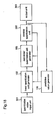
- An image coding apparatus and an image decoding apparatus of Embodiment 15 are those in which a quantization representative point is added to a linear quantizing unit having a linear quantization representative value to realize a non-linear quantization unit performing quantization or reverse quantization.
- a pixel value input unit 101 inputs a pixel value having a dynamic range of d-bit.
- a linear quantization unit generator 102 generates a linear quantization unit having linear quantization representative points.
- a non-linear quantization unit generator 103 adds the quantization representative point to the vicinity of a predictive value to generate a non-linear quantization unit whose quantization width in the vicinity of the predictive value is smaller than that of the linear quantization unit.
- a quantization unit 104 quantizes an input pixel value using the non-linear quantization unit to obtain the quantization value of n-bit.
- An output unit 105 outputs the quantization value obtained in the quantization unit.
- a predictive value generator 106 generates a predictive value for the input pixel value from the peripheral pixels of the input pixel.
- a predictive value of 8-bit is generated for the pixel value from the pixel value input unit 101, as a linear sum obtainable from the quantization value of the peripheral pixels. Based on the predictive value thus generated, a quantization representative value for the input pixel value is set in the linear quantization unit generator 102 and the non-linear quantization unit generator 103.
- the linear quantization unit generator 102 sets linear quantization representative values including the predictive value of 13 as a quantization representative value.
- the generator 102 is assumed to generate 2 n -m linear quantization representative values with quantization width of 2 k , wherein m is previously set as an upper bound value of the quantization representative point to be added in the preceding processing.
- the quantization representative values are set with the quantization width of 4 (2 2 ), positioning the predictive value 13 in the center.
- 1, 5, 9 and 17 , 21 , 25 , 29 are set near 13 in the shown range.
- the number of the quantization representative values set on the whole is 59 (2 6 -5) from the above setting (2 n -m).
- the non-linear quantization unit generator 103 adds not more than m quantization representative points near the above predictive value to reduce the quantization width near the predictive value than that of the linear quantization unit generator.
- the quantization width is set to 1 only around the predictive value.
- Other parts are set to 4 as described.
- the number of the resulting quantization representative values sums up to 63 ( ⁇ 2 6 ), whereby the quantization value after coding is indicated in 6-bit.
- the quantization value for the smallest quantization representative value is set to be -31, and the quantization value is allocated in order of ascending, from the smallest quantization representative value.
- the quantization value of -2 is allocated to the quantization representative value of 1, ..., and 9 is allocated to 29 in this manner.
- the quantization values of -31 to 31 are allocated in order of ascending.
- the quantization unit 104 selects the nearest quantization representative value for an input pixel value to obtain its quantization value, and outputs it to the output unit 105. As shown in Figure 17(d) , when a pixel value is 2, the quantization value is -2, when a pixel value is 14, the quantization value is 14, and the like.
- the quantization representative values are set basically by the linear quantization processing, and the quantization representative values are added only in the vicinity of a predictive value. Therefore in the quantization processing there can perform such an operation processing as employed in linear processing. Even non-linear quantization does not require ROM table and the like. In stead of processing the difference between an input pixel value and a predictive value, the input pixel value is directly quantized, and therefore, the quantization representative value (pixel value) is proportional to the quantization value. Thus, since each quantization value itself contains the absolute level information, even when a predictive value is incorrect, error propagation is hardly caused. In the example illustrated in Figures 17(a) to 17(d) , only four quantization representative values added to the vicinity of the predictive value, i.e., non-linear parts, are affected.
- a quantization value input unit 301 inputs a quantization value as the result of coding.
- a reverse quantization unit 302 performs the reverse quantization of an input quantization value utilizing the non-linear quantization unit generated in the non-linear quantization unit generator 103.
- An output unit 303 outputs the result of decoding. Others are common to the image coding apparatus.
- a predictive value generator 106 When a quantization value as the result of coding is input from the input unit 301, a predictive value generator 106 generates, as a linear sum, a predictive value for the quantization value by utilizing the peripheral pixels of the input quantization value.
- a non-linear quantization unit whose quantization width is small only in the vicinity of the predictive value is generated in the linear quantization unit generator 102 and the non-linear quantization unit generator 103.
- the reverse quantization unit 302 performs the reverse quantization of the quantization value input from the quantization input unit 301, and then outputs the result to the output unit 303.
- the image decoding apparatus of Embodiment 15 realizes the reverse quantization of non-linear quantization without ROM tables and the like, as in the aforesaid coding apparatus. It is therefore able to realize a decoding circuit with a considerably small circuit.
- a predictive value for an input data based on the peripheral data is generated in the predictive value generator 106.
- the linear quantization unit generator 102 and the non-linear quantization unit generator 103 provide that after a quantization representative point is set by linear processing, quantization representative values are added in the vicinity of the predictive value to obtain the non-linear quantization unit generator whose quantization width is small only in the vicinity of the predictive value, thereby performing the quantization or the reverse quantization. Since Embodiment 15 is basically executed in the operation processing utilized in linear quantization, there is required no ROM tables and the like. Required are only a simple adder, subtracter and comparator.
- An image coding apparatus and an image decoding apparatus of Embodiment 16 are those in which a quantization representative point is added to a linear quantizing unit to realize a non-linear quantization unit for obtaining quantization values, like in Embodiment 15. These apparatuses prevent a decrease in dynamic range by a shift function.
- FIG. 19 there is shown the construction of the image decoding apparatus of Embodiment 16.
- a shift value generator 107 generates a shift value according to a specified system. Others are common to Figure 16 , and the descriptions are the same as those of Embodiment 15.
- the predictive value generator 106 When a pixel value is input from the pixel value input unit 101, the predictive value generator 106 generates a predictive value of 8-bit as a liner sum that is obtainable from the quantization values of the peripheral pixels. Based on the predictive value thus generated, the shift value generator 107 generates a shift value that is obtained according to a specified system. Based on the shift predictive value that is obtained by subtracting the above shift value from the above predictive value, the linear quantization unit generator 102 and the non-linear quantization unit generator 103 set quantization representative values for an shift input value that is obtained by subtracting the above shift value from the input pixel value.
- Embodiment 16 differs from Embodiment 15 in that the shift predictive value is used in place of the predictive value.
- the quantization unit 104 selects the nearest quantization representative value of a shift input value, and outputs an allocated quantization value to the output unit 105.
- the quantization representative values are basically added only in the vicinity of the shift predictive value by linear quantization, like Embodiment 15. Even non-linear quantization, there is required no ROM tables and the like. Further, since the input pixel value is shifted and its resulting value is directly quantized, error propagation during predictive coding is satisfactorily prevented.
- FIG. 21 there is shown the construction of the image decoding apparatus of Embodiment 16, in which the above coded data is decoded.
- the shift value generator 107 is the same as that of the image coding apparatus. Others are common to Figure 18 .
- the predictive value generator 106 When a quantization value, i.e., the result of the coding, is input from the quantization value input unit 301, the predictive value generator 106 generates, as a linear sum, a predictive value for the input quantization value by utilizing the peripheral pixels. Based on the predictive value, the shift value generator 107 generates a shift value according to a specified system.
- the linear quantization unit generator 102 and the non-linear quantization unit generator 103 provide a non-linear quantization unit whose quantization width is small only in the vicinity of the predictive value.
- the reverse quantization unit 302 performs the reverse quantization of the quantization value input from the quantization value input unit 301. To the value thus obtained, the shift value is added, followed by decoding. Its result is output to the output unit 303.
- Embodiment 16 realizes, like Embodiment 15, the reverse quantization of non-linear quantization without ROM tables and the like. It is therefore able to realize a decoding circuit with a considerably small circuit.
- the linear quantization unit generator 102 and the non-linear quantization unit generator 103 provide the non-linear quantization by operation processing. It is therefore possible to reduce the circuit scale. This enables to reduce costs and electric power and to satisfactorily prevent the error propagation during the predictive coding.
- Embodiment 16 further provides the following advantage. Based on the predictive value generated in the predictive value generator 106, the shift value generator 107 generates a shift value according to a specified system. Whereas in generating a non-linear quantization unit, instead of such a predictive value, there is employed a shift predictive value that is obtained by subtracting a shift value from a predictive value, thereby avoiding the limit of the dynamic range.
- Embodiment 15 realizes the non-linear quantization with a small circuit and can prevent the error propagation during the predictive coding.
- the maximum number of the linear quantization representative points is obtained by reducing the number of the quantization representative points to be added from the original setting number of 2 k , furthermore, the setting is executed around a predictive point.
- an area exceeding the maximum quantization representative value and an area below the minimum quantization representative value are substantially beyond the object, whereby the dynamic range is restricted.
- the shift of a predictive value due to a shift value allows to extend such a restricted dynamic range in the direction of the shift, leading to the recovery of the range. It is therefore possible to provide dynamic range equivalent to that of the case in which linear quantization is mainly performed.
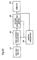
- An image coding apparatus of Embodiment 17 is for obtaining a non-linear quantization value by a linear quantization value generator and a non-linear quantization value generator.
- a linear quantization value generator 401 generates a linear quantization value by the division processing of input pixel value.
- the generator 401 determines an offset value by the remainder of the division processing, and includes an offset value adding means for adding the offset value to the input pixel value.
- a non-linear quantization value generator 402 generates a non-linear quantization value by correcting the above linear quantization value with the difference between the input pixel value and a predictive value.
- the image coding apparatus so constructed will operate as follows.
- a predictive value generator 106 When a pixel value is input from a pixel value input unit 101, a predictive value generator 106 generates a predictive value of 8-bit utilizing the peripheral pixels of the input pixel, as a linear sum obtained from the quantization values of the peripheral pixels.
- the input pixel value from the input unit 101 is also input to the linear quantization value generator 401, in which by the offset value adding means an offset value determined by lower k-bit of the predictive value is added to the input pixel value and then divided with 2 k to be converted into a linear quantization value.
- the "k” is obtained as the difference between the bit number of the dynamic range of the input pixel value and that of the quantization value to be output.
- the linear quantization value is then input to the non-linear quantization value generator 402 to be corrected based on the difference value between the input pixel value and the predictive value, converted into a non-linear quantization value and then output from the output unit 105.
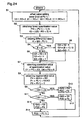
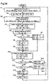
- FIG. 24 there is shown a flow chart of the algorithm of the image coding according to Embodiment 17.
- the quantization operation of the image coding apparatus will be described.
- P(t) denotes the predictive value generated at time t
- I(t) denotes the input pixel value generated at time t
- Q(t) denotes the input pixel value generated at time t
- RO denotes an offset value
- IQ denotes a linear quantization value.
- the regenerative value can be obtained from the predictive value by executing the algorithm.
- step S1 in Figure 24 the offset value adding means of the linear quantization value generator 401 determines an offset value from lower 2-bit of the predictive value P(-1) obtained from the regenerated value at the time immediately before.
- step S2 the offset value is added to the input pixel value by the offset value adding means, and the result is divided by 2 2 in the linear quantization value generator 401, to obtain a linear quantization value.
- step S3 the correction is performed by the non-linear quantization value generator 402.
- step S3 the difference between the predictive value and the input pixel value is obtained.
- step S4 the obtained difference is determined whether it is positive or negative.
- step S5 or S6 a correction value is obtained.
- step S7 a correction value for the quantization value is operated in step S7, and a regenerative value is operated in step S8.
- step S9 and S10 it is determined whether either value is adopted based on the difference value previously obtained. As a result, either of steps S10, S12 and S13 is executed to obtain a quantization value.
- step S10 As described above, the conversion of the input pixel value into the quantization value is completed. Also in step S10, S12 or S13, a regenerative value P(O) is obtained, and in step S14, the regenerative value is then feedbacked so as to use as a predictive value. Then, the operation for obtaining the next quantization value is repeated.
- the image coding apparatus of Embodiment 17 can be executed only by simple add-subtract and the comparison. Although non-linear quantization is employed, there is required no complex circuit such as ROM tables. This algorithm provides the value equivalent to the linear quantized input pixel value as a quantization value, so that the influence of error propagation hardly occurs.
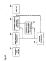
- a linear regenerative value generator 601 generate a linear quantization value for the input quantization value.
- the generator 601 includes an offset value adding means in which an offset value is determined by the remainder of the division operation of a predictive value, and the offset value is added to a linear regenerative value.
- a non-linear quantization regenerative value generator 602 performs a correction by the difference value between an input quantization value and a predictive value linear quantization value.
- a predictive value quantization value generator 603 performs a division operation of the predictive value to obtain a predictive linear quantization value.
- a quantization value input unit 301, an output unit 303 and a predictive value generator 106 are common to Figure 18 , and the descriptions is the same as those of
- the offset value adding means in the linear regenerative generator 601 finds a specified offset value against lower k-bit of the predictive value of the predictive value generator 106.
- the generator 601 performs a multiplication operation of an input quantization value from the quantization value input unit 301 to obtain the value of 2 k , and adds the above offset value to the value 2 k to convert it into a linear quantization regenerative value, and outputs it to the non-linear quantization value generator 602.
- the generator 602 divides the predictive value by 2 k to obtain a predictive linear quantization value, and outputs it to the non-linear quantization value generator 602.
- the generator 602 adds a correction value generated from the difference value between the input quantization value and the predictive linear quantization value to a linear quantization regenerative value or a predictive value, to obtain a quantization regenerative value, and then outputs it to the output unit 303.
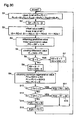
- step S1 the offset value adding means in the linear regenerative value generator 601 sets an offset value by lower 2-bit of the predictive value P(-1) obtained from the quantization regenerative value of immediately before.
- step S2 the predictive value is divided by 2 2 in the predictive value linear quantization value generator 603 to obtain a predictive value linear quantization value PQ.
- step S3 the correction is performed in the non-linear quantization regenerative value generator 602.
- step S3 a difference value between the predictive value linear quantization value and the input quantization value is obtained.
- step S4 it is determined whether the difference is positive or negative.
- step S5 or S6 a correction value is obtained.
- step S9, S11 or S12 is executed to obtain a quantization regenerative value.
- the processing for decoding the input quantization value into the quantization regenerative value is executed.
- the obtained quantization regenerative value is feedbacked in step S13, whereby the operation for obtaining the next quantization regenerative value is repeated.
- the image decoding algorithm employs a non-linear quantization, there is required no ROM table for the reverse quantization. Required are only simple add-subtract. Therefore, irrespective of the suitable change of the quantization representative value due to a predictive value, the decoding processing can be realized with a considerable small circuit.
- the predictive value against the input data is generated based on the peripheral data in the predictive value generator 106.
- the linear quantization value generator 401 and the non-linear quantization value generator 402 provide that after the quantization representative value is set by the linear processing, and the quantization representative value is added to the vicinity of the predictive value to perform a non-linear quantization whose quantization width is small only in the vicinity of the predictive value, thereby obtaining a quantization value.
- This is executed by the operation processing used basically in linear quantization.
- the apparatus can be realized by a simple adder-subtracter. It is therefore possible to reduce the size of the circuit, leading to reduced cost and electric power, permitting a high-speed processing.
- a linear quantization regenerative value is obtained by the linear processing in the linear regenerative value generator 601
- a predictive value linear quantization value is obtained in the predictive value linear quantization value generator 603 based on a predictive value generated in the predictive value generator 106.
- the correction is executed in the non-linear quantization regenerative value generator 602 based on the difference value between the input quantization value and the predictive linear quantization value, to obtain a quantization regenerative value. It is therefore possible to realize the reverse quantization with a small circuit and to reduce costs and electric power.
- An image coding apparatus of Embodiment 18 is for obtaining a quantization representative value by the linear quantization value generator and the non-linear quantization value generator, like in Embodiment 17.
- the apparatus prevents a decrease in dynamic range by a shift function.
- FIG. 27 there is shown the construction of the image decoding apparatus of Embodiment 18.
- a shift value generator 107 generates a shift value according to a specified system. Others are common to Figure 22 , and the descriptions are the same as those of Embodiment 17.
- the image coding apparatus so constructed will operate as follows.
- a predictive value generator 106 When a pixel value is input from a pixel value input unit 101, a predictive value generator 106 generates a predictive value of 8-bit utilizing the peripheral pixels of the input pixel, as a linear sum obtained from the quantization values of the peripheral pixels.
- the shift value generator 107 Based on the generated predictive value, the shift value generator 107 generates a shift value by a specified system. While a shift input value obtained by subtracting the shift value from the input pixel value from the pixel value input unit 101, is input to a linear quantization value generator 401 and, by the offset value adding means, there is added an offset value determined by lower k-bit of the predictive value, and then divided by 2 k to be converted into a linear quantization value.
- the "k” is obtained as the difference between the hit number of the dynamic range of the input pixel value and that of the quantization value to be output.
- the linear quantization value is then input to the non-linear quantization value generator 402 to be corrected based on the difference value between the input pixel value and the predictive value, converted into a non-linear quantization value and then output from the output unit 105.
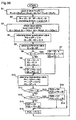
- FIG. 28 there is shown a flow chart of the algorithm of the image coding according to Embodiment 18.
- P(t) denotes the predictive value generated at time t
- Sf is a shift value obtained from the predictive value
- I(t) denotes the input pixel value generated at time t
- Q(t) denotes the input quantization value generated at time t
- RO denotes an offset value
- IQ denotes a linear quantization value.
- step S1 in Figure 28 the shift value generator 107 determines a shift value Sf from upper 5-bit of the obtained predictive value P(-1) obtained from the regenerative value of immediately before.
- step S2 a shift input value obtained by subtracting the shift value from the input pixel value, and a shift predictive value obtained by subtracting the shift value from the predictive value.
- step S3 the offset value adding means in the linear quantization value generator 401 sets an offset value by lower 2-bit of the shift predictive value.
- step S4 after the offset value is added to the shift input value in the offset value adding means and the result is divided by 2 2 in the linear quantization value generator 401, to obtain a linear quantization value.
- step S5 the correction is performed by the non-linear quantization value generator 402.
- step S5 the difference between the predictive value and the input pixel value is obtained.
- step S6 the obtained difference is determined whether it is positive or negative.
- step S7 or S8 a correction value is obtained.
- steps S8 and S9 a correction value for the quantization value is operated in steps S8 and S9, and a regenerative value is operated in step S10.
- steps S11 and S13 it is determined whether either value is adopted based on the difference value previously obtained. As a result, either of steps S12, S14 and S15 is executed to obtain a quantization value.
- step S12 As described above, the conversion of the input pixel value into the quantization value is completed. Also in step S12, S14 or S15, a regenerative value P(O) to which the shift value has been added is obtained, and in step S16, the regenerative value is then feedbacked so as to use as a predictive value. Then, the operation for obtaining the next quantization value is repeated.
- the image coding apparatus of Embodiment 18 can be executed only by simple add-subtract and the comparison. Although non-linear quantization is employed, there is required no complex circuit such as ROM tables. This algorithm also provides the value equivalent to the linear quantized input pixel value as a quantization value, so that the influence of error propagation hardly occurs.
- FIG. 29 there is shown the construction of the image decoding apparatus of Embodiment 18.
- a shift value generator 107 generates a shift value by a specified system. Others are common to Figure 25 , and the descriptions are the same as those of Embodiment 17.
- the shift value generator 107 generates shift value by a specified system, based on the predictive value generated in the predictive value generator 106.
- the offset value adding means in the linear regenerative generator 601 finds a specified offset value based on lower k-bit of the shift predictive value.
- the generator 601 performs a multiplication operation of an input quantization value from the quantization value input unit 301 to obtain the value of 2 k , and adds the above offset value to the value 2 k to convert it into a linear quantization regenerative value, and outputs it to the non-linear quantization value generator 602.
- the generator 602 divides the predictive value by 2 k to obtain a predictive linear quantization value, and outputs it to the non-linear quantization value generator 602.
- the generator 602 adds a correction value generated from the difference value between the input quantization value and the predictive linear quantization value to a linear quantization regenerative value or a predictive value, to obtain a quantization regenerative value, and then outputs it to the output unit 303.
- FIG. 30 there is shown a flow chart of the algorithm for image decoding in Embodiment 18.
- P(t) denotes a quantization regenerative value and a predictive value each being generated at time t
- Q(t) denotes an input quantization value input at time t
- RO denotes an offset value
- PQ denotes a predictive value linear quantization value
- Sf denotes a shift value obtained from the predictive value
- IQ denotes a linear regenerative value.
- the regenerative value at immediately before is used as a predictive value.
- step S1 in Figure 30 the shift value generator 107 determines a shift value Sf by upper 5-bit of the predictive value P(-1) obtained from the regenerative value at immediately before the time.
- stop S2 the shift value is subtracted from the predictive value to obtain a shift predictive value.
- step S3 the offset value adding means in the linear regenerative value generator 601 determines an offset value by lower 2-bit of the predictive value P(-1) obtained from the quantization regenerative value at immediately before the time.
- step S4 the shift predictive value is divided by 2 2 in the predictive value linear quantization value generator 603 to obtain a predictive value linear quantization value PQ.
- step S5 the correction is carried out in the non-linear quantization regenerative value generator 602.
- step S6 a difference value between the predictive value linear quantization value and the input quantization value is obtained.
- step S7 or S8 it is determined whether the difference value is positive or negative.
- step S7 or S8 a correction value is obtained.
- steps S10 and S12. it is determined from the difference value whether either value should be adopted.
- Step S11, 13 or 14 is executed to obtain a quantization regenerative value, a shift value is added thereto and the result is output.
- the image decoding algorithm employs a non-linear quantization, there is required no ROM table for the reverse quantization. Required are only simple add-subtract. Therefore, irrespective of the suitable change of the quantization representative value due to a predictive value, the decoding processing can be realized with a considerable small circuit.
- the predictive value against the input data is generated based on the peripheral data in the predictive value generator 106.
- the linear quantization value generator 401 and the non-linear quantization value generator 402 provide that after the quantization representative value is set by the linear processing, and the quantization representative value is added to the vicinity of the predictive value to perform a non-linear quantization whose quantization width is small only in the vicinity of the predictive value, thereby obtaining a quantization value.
- the realization of the non-linear quantization processing at a small circuit allows to reduce costs and electric power. This permits a high-speed processing and enables to satisfactorily prevent the error propagation during the predictive coding.
- a linear quantization regenerative value is obtained by the linear processing in the linear regenerative value generator 601
- a predictive value linear quantization value is obtained in the predictive value linear quantization value generator 603 based on a predictive value generated in the predictive value generator 106.
- the correction is executed in the non-linear quantization regenerative value generator 602 based on a difference value between the input quantization value and the predictive linear quantization value, to obtain a quantization regenerative value. It is therefore possible to realize the reverse quantization with a small circuit and to reduce costs and electric power.
- the shift value generator 107 Based on a predictive value generated in the predictive value generator 106, the shift value generator 107 generates a shift value by a specified system.
- a shift predictive value that is obtained by subtracting the shift value from the predictive value is employed instead of the predictive value. Therefore, a dynamic range restricted by a decrease of a linear quantization representative value can be recovered by extending the range to the shift direction. This realizes a dynamic range equivalent to that of the case in which linear quantization is mainly performed, like Embodiment 16.
- the correction for obtaining the non-linear quantization value or non-linear quantization regenerative value is carried out based on the difference value between a shift input value and a shift predictive value, it may be based on a difference value between a shift value and a predictive value, resulting in the same effect.
- An image coding apparatus and an image decoding apparatus of Embodiment 19 are those in which quantization representative points are added to a linear quantizing unit to realize a non-linear quantization unit for obtaining a quantization value, and are provided with a function to set quantization representative points to a specific area.
- a non-linear quantization unit generator 701 generates a non-linear quantization unit in which quantization representative points are added to a specific area in addition to the vicinity of a predictive point. Others are common to Figure 16 , and the descriptions are the same as those of Embodiment 15.
- the operations up to the linear quantization unit having linear quantization representative values is generated in the linear quantization unit generator 102, are common to Embodiment 15.
- the linear quantization representative values are generated with the quantization width of 4 (2 2 ), resulting in 59 (2 6 -5).
- FIG. 32(a) there is shown a setting of quantization representative values by the linear quantization unit generator 102.
- an area ranging from -128 to -119 and an area ranging from 119 to 127 are beyond the area to be selected as quantization representative values.
- the non-linear quantization unit generator 701 adds quantization representative values to linear quantization representative values. That is, not more than m-p quantization representative points are added in the vicinity of the predictive value such that the quantization width near the predictive value becomes smaller than that of the linear quantization unit.
- the quantization width turns to be 2, while that of the other area is 4.
- the quantization representative points total 61.
- the quantization width of these area turns to be 8.
- the quantization representative values total 63 ( ⁇ 2 6 ), whereby the quantization value as the coding result is indicated by 6-bit.
- the quantization value allocated for the area ranging from -128 to -119 is -31 being the minimum.
- the quantization representative values are allocated in increasing order like Embodiment 1, so that 31 is allocated for the area ranging from 119 to 127.
- a non-linear quantization unit generator 701 is the same as that of the image coding apparatus. Others arc common to Figure 18 .
- Embodiment 19 The operation of the image decoding apparatus of Embodiment 19 is the same as that of Embodiment 15, except that the quantization representative values of the non-linear quantization unit generated in the non-linear quantization unit generator 701 are those which are shown in Figures 32(a) to 32(d) .
- the image coding and decoding apparatuses of Embodiment 19 are provided with the non-linear quantization unit generator that functions to add quantization representative values to a specific area. Therefore, the dynamic range restriction due to the addition of the quantization representative values to the vicinity of a predictive value, can be reduced by the construction having no function of generating shift values in Embodiment 16.
- An image coding apparatus and an image decoding apparatus of Embodiment 20 are those in which non-linear quantization values are obtained by a linear quantization value generator and a non-linear quantization value generator, and a specified coding or decoding is carried out in reply to the input of a specific area.
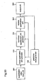
- An input restriction unit 403 examines the magnitude of an input pixel value from a pixel value input unit. When it is within a specified range, the restriction unit 403 outputs the input pixel value to a linear quantization value generator 401, and, when it is beyond the range, does not output the input pixel value but outputs a specified quantization value to a non-linear quantization value generator 402. When the quantization value is output from the restriction unit 403, the generator 402 outputs it to an output unit 105. Others are common to Figure 22 , and the descriptions are the same as those of Embodiment 17.
- the predictive value generator 106 When a pixel value is input from the pixel value input unit 101, the predictive value generator 106 generates a predictive value of 8-bit by utilizing pixels around the input pixel. The input pixel value from the input unit 101 is also input to the input value restriction unit 403 and then determined whether it is within a specified range.
- the input pixel value is input to the linear quantization unit 401, and there is added an offset value which is determined by lower k-bit of the predictive value in the unit 401.
- the obtained value is converted into a linear quantization value by division processing, which value is then corrected in the non-linear quantization value generator 402, based on a difference value between the input value and the predictive value, so that it is converted into a non-linear quantization value and then output from the output unit 106.
- the input value restriction unit 403 when the input pixel value is outside of the specified range, the input value restriction unit 403 generates a non-linear quantization value by a specified system, which value is then input to the generator 402 and output from the output unit 105.
- the input value restriction unit 403 when an input pixel value is in the range of from -118 to 118, the input value restriction unit 403 outputs it to the linear quantization value generator 401.
- the output pixel value is then processed in the generator 401 and the non-linear quantization value generator 402, like the coding apparatus of Embodiment 17, thereby obtaining a quantization value.
- the restriction unit 403 When an input pixel value is in the range of from -128 to -119, or from 119 to 127, the restriction unit 403 does not output it to the generator 401, but generates the non-linear quantization values "-31" or "31", and outputs it to the generator 402. This results in the same coding result like Embodiment 19.
- the unit 301 When a specific one is input to the quantization value input unit 301, the unit 301 outputs it to the non-linear quantization value generator 1201, and the generator 1201 outputs a specified regenerative value to the output unit 308.
- the above specific one is a specified non-linear quantization value that is output to the non-linear quantization value generator 402 from the input value restriction unit 403.
- Other cases are processed in the same operation as in the image decoding apparatus of Embodiment 17.
- the image coding and decoding apparatuses of Embodiment 20 requires no ROM table and the like, thereby realizing the coding/decoding processing at a small circuit.
- the apparatuses function to output a specified value against the input pixel value or quantization value of a specific area. Hence the dynamic range restriction due to the addition of quantization representative values to the vicinity of a predictive value, can be reduced by the construction having no function of generating shift values in Embodiment 16.
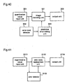
- the image coding apparatus of Embodiment 21 is provided with an input restriction function.
- the image coding apparatus of Embodiment 15 realizes the non-linear quantization by adding quantization representative values to the vicinity of a predictive values of the quantization representative values obtained by linear quantization.
- the number of linear quantization representative values is reduced by the number of quantization representative values to be added.
- the range of quantization in the linear quantization i.e., dynamic range, should be restricted.
- An input value restriction unit 403 restricts he input value.
- An image coding unit 702 comprises the linear quantization unit generator, the non-linear quantization unit generator, the quantization unit and the predictive value generator as shown in Embodiment 15.
- a pixel value input unit 101 and an output unit 105 are common to Figure 16 .
- the image coding apparatus of Embodiment 21 performs the coding in the following operations.
- the input pixel value from the pixel value input unit 101 is input to the input value restriction unit 403, and then restricted to the range for which the quantization can be executed in the linear quantization unit of the image coding unit 702.
- the restricted input value is converted into a quantization value in the coding unit 702, in the same coding processing as in Embodiment 15.
- the obtained value is output to the output unit 105.
- the restriction in the restriction unit 403 should be executed so that the dynamic range of the input pixel value is reduced by at least m ⁇ 2 k levels.
- Lhe input value restriction unit 403 restricts the input pixel values to the range capable of being processed by the linear quantization. It is therefore able to satisfactorily hold the characteristic that a fine image quality is obtainable from the predictive coding in the non-linear quantization processing that prevents the error propagation due to a small circuit.
- image coding unit 702 is constructed according to Embodiment 15, it may be constructed according to Embodiment 17, resulting in the same effect.
- the image coding apparatus of Embodiment 22 is provided with a function to restrict a quantization value.
- a quantization value restriction unit 801 restricts a quantization value. Others are common to Figure 37 .
- the coding is carried out in the following.
- the coding unit 702 converts the input pixel value into a quantization value in the same coding processing as in Embodiment 15, and the obtained value is input to a quantization value restriction unit 801.
- the unit 801 detects the value of the input quantization value and, when it is outside a range of from Lhe minimum value to the maximum value determined to the quantization value, the detective value is restricted to the range and then output to the output unit 105.
- the quantization value as the coding result is restricted to a specific range by the quantization value restriction unit 801, thereby omitting the restriction of the dynamic range of an input value. This enables to obtain the same effect as in Embodiment 21.
- image coding unit 702 is constructed according to Embodiment 15, it may be constructed according to Embodiment 17, resulting in the same effect-
- the image coding apparatus of Embodiment 23 is provided with a function to restrict shift input.
- the linear quantization value generator 102 includes the shift input value restriction means that restricts the shift input value obtained from an input pixel value and a shift value to a specific range. Others are common to Embodiment 18.
- FIG 39 there is shown a flow chart illustrating the coding algorithm of the image coding apparatus of Embodiment 23.
- the flow of Figure 39 differs from that of Figure 28 in that the range of a shift input value is restricted in step S2. Others are common to Embodiment 18.
- the shift input restriction function provides the effect similar to the input restriction function of Embodiment 21.
- the shift input restrictions realizes the restriction depending on the shift value setting, permitting a further flexible application.
- Embodiment 23 is constructed according to Embodiment 18, it may be constructed according to Embodiment 16, resulting in the same effect.
- Embodiment 24 The image coding and decoding apparatus of Embodiment 24 is able to set error codes.
- a quantization value restriction unit 801 enables to prohibit the use of a pattern of a specified n-bit in a normal quantization. This further enables to allocate an error code showing an error in a quantization value, to such a pattern not to be used.
- a quantization value is in 6-bit, the numerals from -31 to 31 are utilized in the quantization, and -32 is set to an error code.
- An image decoding unit 901 comprises the linear quantization unit generator, the non-linear quantization unit generator and the predictive value generator shown in Figure 18 , and the unit 901 performs the same decoding processing as the image decoding apparatus of Embodiment 15.
- An error code detector 902 detects an error code of an input quantization value.
- a predictive error setting unit 903 sets a difference from a predictive value.
- An input quantization value from the quantization value input unit 301 is first determined whether it is error code or not in the error code detector 902. For an error code, the difference from a predictive value is set to be 0 in the image decoding unit 901 through the predictive error setting unit 903, thereby outputting the predictive value as it is to the output unit 303. When an input quantization value is not an error code, a normal decoding is carried out in the decoding unit 901 and its result is output to the output unit 303.
- the predictive value is output as a regenerative value.
- a regenerative value input unit 9101 regenerates a coded data.
- An error code replacement unit 9102 replaces a quantization value of a regenerative data with an error code.
- An error detector 9103 detects an error of a regenerative data.
- An output unit 9104 outputs data after the replacement.
- the error detector 9103 detects whether there is an error in data regenerated from a magnetic tape or a transmission signal in the input unit 9101. The quantization value whose error is detected in the detector 9103 is then replaced with an error code in the error code replacement unit 9102. In this way, the quantization value that may have an error is replaced with an error code and then output to the output unit 9104.
- the image coding and decoding apparatuses of Embodiment 24 are provided with the quantization value input unit 301, thereby setting a specific quantization value as an error code.
- the obtained coded data is subjected to the error code replacement processing by the error code insertion circuit as described. Therefore, in the image decoding apparatus provided with the error code detector 902 and the predictive error setting unit 903, when an error code is detected, a predictive value itself is employed as a regenerative value, thereby minimizing the influence of the error.
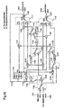
- a pixel value input unit 1101, a quantization value input unit 1102, a quantization regenerative value output unit 1103 and a quantization value output unit 1104 are those which are shown in Figure 16 and Figure 18 in Embodiment 15.
- Numerals 1105 to 1112 designate switches, 1113 to 1123 designate adder-subtracters, 1124 and 1125 designate comparators, and 1126 and 1127 designate delay units.
- the coding processing and the decoding processing can be switched, permitting to share almost of all circuits. This enables to considerably reduce the circuit size, leading to the reduced costs and effective applications of the device resource.
- the invention can comply with optional image signal.
- the bit numbers of an input pixel value and a quantization value and the like are applicable.
- the constructions illustrated in the embodiments can be realized in a variety of methods and processing order, and also be realized by software. Additionally, the image coding apparatus and decoding apparatuses utilizing a combination of the above mentioned plural techniques are available.
Landscapes
- Engineering & Computer Science (AREA)
- Multimedia (AREA)
- Signal Processing (AREA)
- Library & Information Science (AREA)
- Computer Networks & Wireless Communication (AREA)
- Databases & Information Systems (AREA)
- Compression Or Coding Systems Of Tv Signals (AREA)
- Television Signal Processing For Recording (AREA)
- Compression, Expansion, Code Conversion, And Decoders (AREA)
Description
- The present invention relates to an image coding apparatus for compressing and recording image data from video signals by coding, and an image decoding apparatus for regenerating the coded and recorded image.
- Recently there have been developed various video signal recorder that code and compress video signals of digital data by a specified mode and perform a digital recording. It is, however, required much expenses and labor for the standardization of compression modes and compressed algorithm hardware, e.g., LSI. In order to reduce the development costs for early development, it is preferable to apply a known standard and its corresponding accumulated techniques, a known hardware of compressed algorithms and the like. Hence there have been developed novel video signal recorders depending on the purpose.
- When obtaining digital data to be treated by computers and the like, based on the video signal of such as TV signal, it is general that image data comprising digitized video signal is first obtained, the image data is then compressed and coded, and the obtained data is recorded or transmitted. The digitized image data is in a sequence of pixel data having pixel values indicating luminance and chrominance, and the image data is coded by processing to obtain coded image data.
- As a general method for compressing/coding image data based on video signal, there is predictive coding. The predictive coding is a system in which a predictive value for an input pixel that is the object of coding is generated, and a difference value between the input pixel and the predictive value is subjected to non-linear quantization, the obtained data is then transmitted. When the image from video signal is treated, a predictive value is obtained by predicting a pixel value at a certain point, from its periphery pixels, based on that adjacent parts tends to have the same or an approximate pixel value indicating luminance and chrominance. The predictive coding has the advantages that the circuit scale for an apparatus is small and the compression rate is low. When data rate after compression is high, high-quality image is obtainable. This is the reason why the predictive coding has been widely used.
-
Figure 43 is a conceptual diagram explaining the linear processing and non-linear processing in quantization. Input data has a certain dynamic range. That is, the input data is represented in the range of d-bit as a dynamic range, and, the linear processing is possible. When n-bit output data is obtained by quantizing the input data, a suitable number of quantization representative values are selected, and quantizing values are allocated to the representative values. To each input data, there is given a quantizing value allocated to a quantization representative value that is approximate to the input data. By setting the number of the quantization representative values to not more than 2n, the output data can be treated by n-bit. - As shown in
Figure 43 , to set quantization representative values at uniform intervals is linear quantization. When an expected value is previously obtained as in the predictive coding, non-linear quantization in which the quantisation representative values are set densely in the vicinity of the expected value, and widely as the distance from the expected value is increased. - In
Figure 43 , there is shown a rounding processing of from 3-bit to 2-bit. By setting four (22) quantization representative values against eight (23) ones, the output data can be represented by 2-bit. - In the linear processing, the quantizing representative values are set, for example, by selecting every other piece, to assign the quantizing value. For input data having the values from 0 to 7, they are replaced with the adjacent quantizing representative value to give a quantizing value assigned to the respective representative value in the following manner. For the value of 0 or 1, its quantizing representative value is 0, for the value of 2 or 3, its quantizing value is 2, and the like.
- In the non-linear processing, when an expected value for the input data is 3, for example, the setting of quantizing values will be set densely in the vicinity of 3, and roughly as the distance from 3 is increased. As the quantizing width is creased, that is, as the interval of the quantizing representative values is increased, the number of data replaceable with the quantizing representative value is increased. This shows that data of different value tends to be treated equally. Therefore, nearer the vicinity of the expected value, the magnitude of the quantizing value reflects more precisely the magnitude of the input value.
- The non-linear quantization utilized in the predictive coding is performed in various systems. Since it is normally difficult to perform the non-linear quantization by such a simple operation as in the linear quantization, that is performed by referring to a table such as a ROM table. This might increase the circuit scale and the processing costs, resulting in the cost increase and the reduced processing speed.
- On the other hand, the predictive coding has the problem that transmitted data is a difference value between an input value and a predictive value and, when an error of the predictive value occurs, such an error will be propagated at the regeneration. Thus in order to suppress such an error propagation within a certain range, there has been employed a method of inserting a PCM value periodically. This method, however, decreases the compression rate and causes the unevenness in image quality, failing to solve the problem.
- A method of preventing the error propagation without reduction in compression rate is disclosed, for example, in Japanese Patent Application No.
60-160599 - It is an object of the invention to provide a image coding apparatus that performs non-linear quantization processing at high speed and with a small circuit scale, without ROM tables, and prevents the error propagation during predictive coding without reduction in compression rate.
- It is yet another object of the invention to provide a image decoding apparatus that performs decoding processing at high speed and with a small circuit scale, without ROM table.
- Other objects and advantages of the present invention will become apparent from the detailed description given hereinafter; it should be understood, however, that the detailed description and specific embodiment are given by way of illustration only, since various changes and modifications within the scope of the invention will become apparent to the those skilled in the art from this detailed description.
- According to the invention there is provided an image coding apparatus according to
claim 1. - According to another aspect the invention provides an image decoding apparatus according to
claim 10. -
-
Figure 16 is a block diagram showing a construction of a image coding apparatus ofEmbodiment 15 of the invention. -
Figures 17(a) to 17(d) are diagrams for explaining the quantization of the image coding apparatus ofEmbodiment 15. -
Figure 18 is a block diagram showing a construction of the image decoding apparatus ofEmbodiment 15. -
Figure 19 is a block diagram showing a construction of an image coding apparatus ofEmbodiment 16 of the invention. -
Figures 20(a) to 20(d) are diagrams for explaining the quantization of the image coding apparatus ofEmbodiment 16. -
Figure 21 is a block diagram showing a construction of an image decoding apparatus ofEmbodiment 16. -
Figure 22 is a block diagram showing a construction of an image coding apparatus ofEmbodiment 17 of the invention. -
Figures 23(a) to 23(d) are diagrams for explaining the quantization of the image coding apparatus ofEmbodiment 17. -
Figure 24 is a flow chart showing a coding algorithm of the image coding apparatus ofEmbodiment 17. -
Figure 25 is a block diagram showing a construction of an image decoding apparatus ofEmbodiment 17. -
Figure 26 is a flow chart showing a decoding algorithm of the image decoding apparatus ofEmbodiment 17. -
Figure 27 is a block diagram showing a construction of an image coding apparatus ofEmbodiment 18 of the invention. -
Figure 28 is a flow chart showing a coding algorithm of the image coding apparatus ofEmbodiment 18. -
Figure 29 is a block diagram showing a construction of an image decoding apparatus ofEmbodiment 18. -
Figure 30 is a flow chart showing a decoding algorithm of the image decoding apparatus ofEmbodiment 18. -
Figure 31 is a block diagram showing a construction of an image coding apparatus ofEmbodiment 19 of the invention. -
Figure 32(a) to 32(d) are diagram for explaining the quantization of the image coding apparatus ofEmbodiment 19. -
Figure 33 is a block diagram showing a construction of an image decoding apparatus ofEmbodiment 19. -
Figure 34 is a block diagram showing a construction of an image coding apparatus ofEmbodiment 20 of the invention. -
Figure 35 is a block diagram showing a construction of an image decoding apparatus ofEmbodiment 20. -
Figure 36(a) and 36(b) are diagrams for explaining the coding of the image coding apparatus and the decoding of the image decoding apparatus ofEmbodiment 20. -
Figure 37 is a block diagram showing a construction of an image coding apparatus ofEmbodiment 21 of the invention. -
Figure 38 is a block diagram showing a construction of an image coding apparatus ofEmbodiment 22 of the invention. -
Figure 39 is a flow chart showing a coding algorithm of an image coding apparatus ofEmbodiment 23 of the invention. -
Figure 40 is a block diagram showing a construction of an image decoding apparatus ofEmbodiment 24 of the invention. -
Figure 41 is a block diagram showing a construction of an error code processing unit of the image decoding apparatus ofEmbodiment 24. -
Figure 42 is a block diagram showing a construction of a circuit shared between an image coding apparatus and an image decoding apparatus ofEmbodiment 25 of the invention. -
Figure 43 is a diagram for explaining a non-linear quantization processing of a conventional image coding apparatus. - An image coding apparatus and an image decoding apparatus of
Embodiment 15 are those in which a quantization representative point is added to a linear quantizing unit having a linear quantization representative value to realize a non-linear quantization unit performing quantization or reverse quantization. - Referring to
Figure 16 , there is shown the construction of the image coding apparatus ofEmbodiment 15. A pixelvalue input unit 101 inputs a pixel value having a dynamic range of d-bit. A linearquantization unit generator 102 generates a linear quantization unit having linear quantization representative points. A non-linearquantization unit generator 103 adds the quantization representative point to the vicinity of a predictive value to generate a non-linear quantization unit whose quantization width in the vicinity of the predictive value is smaller than that of the linear quantization unit. Aquantization unit 104 quantizes an input pixel value using the non-linear quantization unit to obtain the quantization value of n-bit. Anoutput unit 105 outputs the quantization value obtained in the quantization unit. Apredictive value generator 106 generates a predictive value for the input pixel value from the peripheral pixels of the input pixel. - The operation of the image coding apparatus so constructed will be described. For shortness' sake, assuming that the input pixel value is indicated by 8-bit (d) and the quantization value after being coded is 6-bit (n) wherein n=6, k=d-n=2; and that in order to add quantization representative points, the upper limit number of the addition (m) is 5, which number is previously set.
- In the
predictive value generator 106, utilizing the peripheral pixels of the input pixel, a predictive value of 8-bit is generated for the pixel value from the pixelvalue input unit 101, as a linear sum obtainable from the quantization value of the peripheral pixels. Based on the predictive value thus generated, a quantization representative value for the input pixel value is set in the linearquantization unit generator 102 and the non-linearquantization unit generator 103. - Referring to
Figures 17(a) to 17(d) , there is shown an example of setting of quantization representative values, in which the predictive value is assumed to be 13. - The linear
quantization unit generator 102 sets linear quantization representative values including the predictive value of 13 as a quantization representative value. Thegenerator 102 is assumed to generate 2n-m linear quantization representative values with quantization width of 2k, wherein m is previously set as an upper bound value of the quantization representative point to be added in the preceding processing. In this example, the quantization representative values are set with the quantization width of 4 (22), positioning thepredictive value 13 in the center. As shown inFigure 17(a) , 1, 5, 9 and17 ,21 ,25 ,29 are set near 13 in the shown range. The number of the quantization representative values set on the whole is 59 (26-5) from the above setting (2n-m). - The non-linear
quantization unit generator 103 adds not more than m quantization representative points near the above predictive value to reduce the quantization width near the predictive value than that of the linear quantization unit generator. In this example, 4 (4<m=5) quantization representative values are added in the range of two levels around the predictive value of 13. As a result, the quantization width is set to 1 only around the predictive value. Other parts are set to 4 as described. The number of the resulting quantization representative values sums up to 63 (<26), whereby the quantization value after coding is indicated in 6-bit. - Subsequently the quantization value for the smallest quantization representative value is set to be -31, and the quantization value is allocated in order of ascending, from the smallest quantization representative value. As shown in
Figure 17(c) , the quantization value of -2 is allocated to the quantization representative value of 1, ..., and 9 is allocated to 29 in this manner. On the whole, the quantization values of -31 to 31 are allocated in order of ascending. - The
quantization unit 104 selects the nearest quantization representative value for an input pixel value to obtain its quantization value, and outputs it to theoutput unit 105. As shown inFigure 17(d) , when a pixel value is 2, the quantization value is -2, when a pixel value is 14, the quantization value is 14, and the like. - As described above, in the image coding apparatus of
Embodiment 15, the quantization representative values are set basically by the linear quantization processing, and the quantization representative values are added only in the vicinity of a predictive value. Therefore in the quantization processing there can perform such an operation processing as employed in linear processing. Even non-linear quantization does not require ROM table and the like. In stead of processing the difference between an input pixel value and a predictive value, the input pixel value is directly quantized, and therefore, the quantization representative value (pixel value) is proportional to the quantization value. Thus, since each quantization value itself contains the absolute level information, even when a predictive value is incorrect, error propagation is hardly caused. In the example illustrated inFigures 17(a) to 17(d) , only four quantization representative values added to the vicinity of the predictive value, i.e., non-linear parts, are affected. - Referring to
Figure 18 , there is shown a construction of the image decoding apparatus ofEmbodiment 15. A description will be given of the operation when this apparatus decodes the data coded as described above. - A quantization
value input unit 301 inputs a quantization value as the result of coding. Areverse quantization unit 302 performs the reverse quantization of an input quantization value utilizing the non-linear quantization unit generated in the non-linearquantization unit generator 103. Anoutput unit 303 outputs the result of decoding. Others are common to the image coding apparatus. - The operation of the image decoding apparatus so constructed will be described. When a quantization value as the result of coding is input from the
input unit 301, apredictive value generator 106 generates, as a linear sum, a predictive value for the quantization value by utilizing the peripheral pixels of the input quantization value. - Similar to the image coding apparatus, based on the predictive value generated in the
predictive value generator 106, a non-linear quantization unit whose quantization width is small only in the vicinity of the predictive value is generated in the linearquantization unit generator 102 and the non-linearquantization unit generator 103. Utilizing the quantization unit thus obtained, thereverse quantization unit 302 performs the reverse quantization of the quantization value input from thequantization input unit 301, and then outputs the result to theoutput unit 303. - Therefore, the image decoding apparatus of
Embodiment 15 realizes the reverse quantization of non-linear quantization without ROM tables and the like, as in the aforesaid coding apparatus. It is therefore able to realize a decoding circuit with a considerably small circuit. - Thus in the image coding apparatus and the image decoding apparatus of
Embodiment 15, a predictive value for an input data based on the peripheral data is generated in thepredictive value generator 106. The linearquantization unit generator 102 and the non-linearquantization unit generator 103 provide that after a quantization representative point is set by linear processing, quantization representative values are added in the vicinity of the predictive value to obtain the non-linear quantization unit generator whose quantization width is small only in the vicinity of the predictive value, thereby performing the quantization or the reverse quantization. SinceEmbodiment 15 is basically executed in the operation processing utilized in linear quantization, there is required no ROM tables and the like. Required are only a simple adder, subtracter and comparator. By reducing the circuit scale, it is able to reduce costs and electric power and to realize high-speed processing. In the quantization and the reverse quantization, the object of the processing is input values, not differences. Therefore even when the predictive value is incorrect, the above mentioned small circuit can minimize the error propagation without lowering the compressive rate. - An image coding apparatus and an image decoding apparatus of
Embodiment 16 are those in which a quantization representative point is added to a linear quantizing unit to realize a non-linear quantization unit for obtaining quantization values, like inEmbodiment 15. These apparatuses prevent a decrease in dynamic range by a shift function. - Referring to
Figure 19 , there is shown the construction of the image decoding apparatus ofEmbodiment 16. Ashift value generator 107 generates a shift value according to a specified system. Others are common toFigure 16 , and the descriptions are the same as those ofEmbodiment 15. - The operation of the image coding apparatus so constructed will be described. Similar to
Embodiment 15, assuming that an input pixel value is indicated in 8-bit (d) and the quantization value after the coding is 6-bit (n), wherein n-6, k-d-n=2, and the addition upper bound number m =5. - When a pixel value is input from the pixel
value input unit 101, thepredictive value generator 106 generates a predictive value of 8-bit as a liner sum that is obtainable from the quantization values of the peripheral pixels. Based on the predictive value thus generated, theshift value generator 107 generates a shift value that is obtained according to a specified system. Based on the shift predictive value that is obtained by subtracting the above shift value from the above predictive value, the linearquantization unit generator 102 and the non-linearquantization unit generator 103 set quantization representative values for an shift input value that is obtained by subtracting the above shift value from the input pixel value. - Referring to
Figures 20(a) to 20(d) , there are shown an example of the setting of the quantization representative point inEmbodiment 16.Embodiment 16 differs fromEmbodiment 15 in that the shift predictive value is used in place of the predictive value. - The
quantization unit 104 selects the nearest quantization representative value of a shift input value, and outputs an allocated quantization value to theoutput unit 105. - In the image coding apparatus of
Embodiment 16, the quantization representative values are basically added only in the vicinity of the shift predictive value by linear quantization, likeEmbodiment 15. Even non-linear quantization, there is required no ROM tables and the like. Further, since the input pixel value is shifted and its resulting value is directly quantized, error propagation during predictive coding is satisfactorily prevented. - Referring to
Figure 21 , there is shown the construction of the image decoding apparatus ofEmbodiment 16, in which the above coded data is decoded. Theshift value generator 107 is the same as that of the image coding apparatus. Others are common toFigure 18 . - A description will be given of the operation of the image decoding apparatus of
Embodiment 16. When a quantization value, i.e., the result of the coding, is input from the quantizationvalue input unit 301, thepredictive value generator 106 generates, as a linear sum, a predictive value for the input quantization value by utilizing the peripheral pixels. Based on the predictive value, theshift value generator 107 generates a shift value according to a specified system. - Similar to the image coding apparatus, the linear
quantization unit generator 102 and the non-linearquantization unit generator 103 provide a non-linear quantization unit whose quantization width is small only in the vicinity of the predictive value. Utilizing the obtained non-linear quantization unit, thereverse quantization unit 302 performs the reverse quantization of the quantization value input from the quantizationvalue input unit 301. To the value thus obtained, the shift value is added, followed by decoding. Its result is output to theoutput unit 303. - The image decoding apparatus of
Embodiment 16 realizes, likeEmbodiment 15, the reverse quantization of non-linear quantization without ROM tables and the like. It is therefore able to realize a decoding circuit with a considerably small circuit. - Thus in the image coding and decoding apparatuses of
Embodiment 16, the linearquantization unit generator 102 and the non-linearquantization unit generator 103 provide the non-linear quantization by operation processing. It is therefore possible to reduce the circuit scale. This enables to reduce costs and electric power and to satisfactorily prevent the error propagation during the predictive coding. -
Embodiment 16 further provides the following advantage. Based on the predictive value generated in thepredictive value generator 106, theshift value generator 107 generates a shift value according to a specified system. Whereas in generating a non-linear quantization unit, instead of such a predictive value, there is employed a shift predictive value that is obtained by subtracting a shift value from a predictive value, thereby avoiding the limit of the dynamic range. - Specifically,
Embodiment 15 realizes the non-linear quantization with a small circuit and can prevent the error propagation during the predictive coding. InEmbodiment 15, however, the maximum number of the linear quantization representative points is obtained by reducing the number of the quantization representative points to be added from the original setting number of 2k, furthermore, the setting is executed around a predictive point. As a result, in a dynamic range, an area exceeding the maximum quantization representative value and an area below the minimum quantization representative value are substantially beyond the object, whereby the dynamic range is restricted. - Whereas in
Embodiment 16, the shift of a predictive value due to a shift value allows to extend such a restricted dynamic range in the direction of the shift, leading to the recovery of the range. It is therefore possible to provide dynamic range equivalent to that of the case in which linear quantization is mainly performed. - An image coding apparatus of
Embodiment 17 is for obtaining a non-linear quantization value by a linear quantization value generator and a non-linear quantization value generator. - Referring to
Figure 22 , there is shown the construction of the image decoding apparatus ofEmbodiment 17. A linearquantization value generator 401 generates a linear quantization value by the division processing of input pixel value. Thegenerator 401 determines an offset value by the remainder of the division processing, and includes an offset value adding means for adding the offset value to the input pixel value. A non-linearquantization value generator 402 generates a non-linear quantization value by correcting the above linear quantization value with the difference between the input pixel value and a predictive value. Others are common toFigure 16 , and the descriptions are the same as those ofEmbodiment 15. - The image coding apparatus so constructed will operate as follows. When a pixel value is input from a pixel
value input unit 101, apredictive value generator 106 generates a predictive value of 8-bit utilizing the peripheral pixels of the input pixel, as a linear sum obtained from the quantization values of the peripheral pixels. The input pixel value from theinput unit 101 is also input to the linearquantization value generator 401, in which by the offset value adding means an offset value determined by lower k-bit of the predictive value is added to the input pixel value and then divided with 2k to be converted into a linear quantization value. The "k" is obtained as the difference between the bit number of the dynamic range of the input pixel value and that of the quantization value to be output. - The linear quantization value is then input to the non-linear
quantization value generator 402 to be corrected based on the difference value between the input pixel value and the predictive value, converted into a non-linear quantization value and then output from theoutput unit 105. - A description will be given of the algorithm for image coding. Similar to
Embodiment 15, assuming that the input pixel value is indicated by 8-bit (d), and the quantization value after the coding is 6-bit (n) (n=6, k=d-n=2). As shown inFigures 23(a) to 23(d) , when setting quantization representative values, to linear quantization representative values with quantization width of 4, there are set six quantization representative values consisting of four quantization representative values with quantization width of 1, adjacent to a predictive value (i.e., 13 inFigures 23(a) to 23(d) ), and two quantization representative values with quantization width of 2. - Referring to
Figure 24 , there is shown a flow chart of the algorithm of the image coding according toEmbodiment 17. The quantization operation of the image coding apparatus will be described. InFigure 24 , P(t) denotes the predictive value generated at time t, I(t) denotes the input pixel value generated at time t, Q(t) denotes the input pixel value generated at time t, RO denotes an offset value and IQ denotes a linear quantization value. For the sake for simplicity, assuming that there is used a regenerated value of immediately before. The regenerative value can be obtained from the predictive value by executing the algorithm. - In step S1 in
Figure 24 , the offset value adding means of the linearquantization value generator 401 determines an offset value from lower 2-bit of the predictive value P(-1) obtained from the regenerated value at the time immediately before. In step S2, the offset value is added to the input pixel value by the offset value adding means, and the result is divided by 22 in the linearquantization value generator 401, to obtain a linear quantization value. - From step S3, the correction is performed by the non-linear
quantization value generator 402. In step S3, the difference between the predictive value and the input pixel value is obtained. In step S4, the obtained difference is determined whether it is positive or negative. In step S5 or S6, a correction value is obtained. Based on the results, a correction value for the quantization value is operated in step S7, and a regenerative value is operated in step S8. In step S9 and S10, it is determined whether either value is adopted based on the difference value previously obtained. As a result, either of steps S10, S12 and S13 is executed to obtain a quantization value. - As described above, the conversion of the input pixel value into the quantization value is completed. Also in step S10, S12 or S13, a regenerative value P(O) is obtained, and in step S14, the regenerative value is then feedbacked so as to use as a predictive value. Then, the operation for obtaining the next quantization value is repeated.
- As can be seen from the above algorithm, the image coding apparatus of
Embodiment 17 can be executed only by simple add-subtract and the comparison. Although non-linear quantization is employed, there is required no complex circuit such as ROM tables. This algorithm provides the value equivalent to the linear quantized input pixel value as a quantization value, so that the influence of error propagation hardly occurs. - Referring to
Figure 25 , there is shown the construction of the image decoding:apparatus ofEmbodiment 17. A linearregenerative value generator 601 generate a linear quantization value for the input quantization value. Thegenerator 601 includes an offset value adding means in which an offset value is determined by the remainder of the division operation of a predictive value, and the offset value is added to a linear regenerative value. A non-linear quantizationregenerative value generator 602 performs a correction by the difference value between an input quantization value and a predictive value linear quantization value. A predictive valuequantization value generator 603 performs a division operation of the predictive value to obtain a predictive linear quantization value. A quantizationvalue input unit 301, anoutput unit 303 and apredictive value generator 106 are common toFigure 18 , and the descriptions is the same as those of - A description will be given of the operation of the image decoding apparatus of
Embodiment 17. - The offset value adding means in the linear
regenerative generator 601 finds a specified offset value against lower k-bit of the predictive value of thepredictive value generator 106. Thegenerator 601 performs a multiplication operation of an input quantization value from the quantizationvalue input unit 301 to obtain the value of 2k, and adds the above offset value to thevalue 2k to convert it into a linear quantization regenerative value, and outputs it to the non-linearquantization value generator 602. - The
generator 602 divides the predictive value by 2k to obtain a predictive linear quantization value, and outputs it to the non-linearquantization value generator 602. Thegenerator 602 adds a correction value generated from the difference value between the input quantization value and the predictive linear quantization value to a linear quantization regenerative value or a predictive value, to obtain a quantization regenerative value, and then outputs it to theoutput unit 303. - A description will be given of the algorithm for image decoding. Assuming that an input pixel value at the coding and a regenerative value are indicated in 8-bit (d), a regenerative value after the decoding is indicated in 8-bit, and the quantization value after the coding is indicated in 6-bit (n) (n=6, k=d-n=2). In setting quantization representative values, similar to the coding apparatus, six quantization representative values are added and then provided, as shown in
Figure 23 . - Referring to
Figure 26 , there is shown a flow chart of the algorithm for image decoding inEmbodiment 17.
According to the flowchart, a description will be given of the algorithm for non-linear quantization value operation. Assuming that P(t) denotes a quantization regenerative value and a predictive value each being generated at time t, Q(t) denotes an input quantization value input at time t, RO denotes an offset value, PQ denotes a predictive value linear quantization value and IQ denotes a linear regenerative value. For the sake of simplicity, assuming that the regenerative value at immediately before is used as a predictive value. - In step S1, the offset value adding means in the linear
regenerative value generator 601 sets an offset value by lower 2-bit of the predictive value P(-1) obtained from the quantization regenerative value of immediately before. In step S2, the predictive value is divided by 22 in the predictive value linearquantization value generator 603 to obtain a predictive value linear quantization value PQ. - From step S3, the correction is performed in the non-linear quantization
regenerative value generator 602. In step S3, a difference value between the predictive value linear quantization value and the input quantization value is obtained. In step S4, it is determined whether the difference is positive or negative. In step S5 or S6. a correction value is obtained. Based on the results, the operation of a correction regenerative value is operated in step S7, and steps S8 and S10, based on the obtained difference value, it is determined whether either value should be adopted. Step S9, S11 or S12 is executed to obtain a quantization regenerative value. - As described above, the processing for decoding the input quantization value into the quantization regenerative value is executed. The obtained quantization regenerative value is feedbacked in step S13, whereby the operation for obtaining the next quantization regenerative value is repeated.
- Although the image decoding algorithm employs a non-linear quantization, there is required no ROM table for the reverse quantization. Required are only simple add-subtract. Therefore, irrespective of the suitable change of the quantization representative value due to a predictive value, the decoding processing can be realized with a considerable small circuit.
- In the image coding apparatus of
Embodiment 17, the predictive value against the input data is generated based on the peripheral data in thepredictive value generator 106. The linearquantization value generator 401 and the non-linearquantization value generator 402 provide that after the quantization representative value is set by the linear processing, and the quantization representative value is added to the vicinity of the predictive value to perform a non-linear quantization whose quantization width is small only in the vicinity of the predictive value, thereby obtaining a quantization value. This is executed by the operation processing used basically in linear quantization. Hence, without ROM tables and the like, the apparatus can be realized by a simple adder-subtracter. It is therefore possible to reduce the size of the circuit, leading to reduced cost and electric power, permitting a high-speed processing. - In the image decoding apparatus of
Embodiment 17, a linear quantization regenerative value is obtained by the linear processing in the linearregenerative value generator 601, a predictive value linear quantization value is obtained in the predictive value linearquantization value generator 603 based on a predictive value generated in thepredictive value generator 106. Based on the results, the correction is executed in the non-linear quantizationregenerative value generator 602 based on the difference value between the input quantization value and the predictive linear quantization value, to obtain a quantization regenerative value. It is therefore possible to realize the reverse quantization with a small circuit and to reduce costs and electric power. - In the quantization and the reverse quantization there is processed an input value not a difference. Even when the predictive value is incorrect, the error propagation can be minimize without reducing the compressive rate. This enables to realize with such a small circuit as described.
- An image coding apparatus of
Embodiment 18 is for obtaining a quantization representative value by the linear quantization value generator and the non-linear quantization value generator, like inEmbodiment 17. The apparatus prevents a decrease in dynamic range by a shift function. - Referring to
Figure 27 , there is shown the construction of the image decoding apparatus ofEmbodiment 18. Ashift value generator 107 generates a shift value according to a specified system. Others are common toFigure 22 , and the descriptions are the same as those ofEmbodiment 17. - The image coding apparatus so constructed will operate as follows. When a pixel value is input from a pixel
value input unit 101, apredictive value generator 106 generates a predictive value of 8-bit utilizing the peripheral pixels of the input pixel, as a linear sum obtained from the quantization values of the peripheral pixels. Based on the generated predictive value, theshift value generator 107 generates a shift value by a specified system. While a shift input value obtained by subtracting the shift value from the input pixel value from the pixelvalue input unit 101, is input to a linearquantization value generator 401 and, by the offset value adding means, there is added an offset value determined by lower k-bit of the predictive value, and then divided by 2k to be converted into a linear quantization value. The "k" is obtained as the difference between the hit number of the dynamic range of the input pixel value and that of the quantization value to be output. - The linear quantization value is then input to the non-linear
quantization value generator 402 to be corrected based on the difference value between the input pixel value and the predictive value, converted into a non-linear quantization value and then output from theoutput unit 105. - A description will be given of the algorithm for image coding.
Similar Lo Embodiment 17, assuming that the input pixel value is indicated by 8-bit (d), and the quantization value after the coding is 6-bit (n) (n=6, k=d-n=2). When setting quantization representative values, likeEmbodiment 17, there are added six quantization representative values consisting of four quantization representative values with quantization width of 1, and two quantization representative values with quantization width of 2. It is noted that the predictive value is employed instead of the shift predictive value. - Referring to
Figure 28 , there is shown a flow chart of the algorithm of the image coding according toEmbodiment 18. The quantization operation of the image coding apparatus will be described. InFigure 28 , P(t) denotes the predictive value generated at time t, Sf is a shift value obtained from the predictive value, I(t) denotes the input pixel value generated at time t, Q(t) denotes the input quantization value generated at time t, RO denotes an offset value and IQ denotes a linear quantization value. For the sake for simplicity, assuming that there is used a regenerative value of immediately before. The regenerative value can be obtained from the predictive value by executing the algorithm. - In step S1 in
Figure 28 , theshift value generator 107 determines a shift value Sf from upper 5-bit of the obtained predictive value P(-1) obtained from the regenerative value of immediately before. In step S2, a shift input value obtained by subtracting the shift value from the input pixel value, and a shift predictive value obtained by subtracting the shift value from the predictive value. In step S3, the offset value adding means in the linearquantization value generator 401 sets an offset value by lower 2-bit of the shift predictive value. In step S4, after the offset value is added to the shift input value in the offset value adding means and the result is divided by 22 in the linearquantization value generator 401, to obtain a linear quantization value. - From step S5, the correction is performed by the non-linear
quantization value generator 402. In step S5, the difference between the predictive value and the input pixel value is obtained. In step S6, the obtained difference is determined whether it is positive or negative. In step S7 or S8, a correction value is obtained. Based on the results, a correction value for the quantization value is operated in steps S8 and S9, and a regenerative value is operated in step S10. In steps S11 and S13, it is determined whether either value is adopted based on the difference value previously obtained. As a result, either of steps S12, S14 and S15 is executed to obtain a quantization value. - As described above, the conversion of the input pixel value into the quantization value is completed. Also in step S12, S14 or S15, a regenerative value P(O) to which the shift value has been added is obtained, and in step S16, the regenerative value is then feedbacked so as to use as a predictive value. Then, the operation for obtaining the next quantization value is repeated.
- As can be seen from the above algorithm, the image coding apparatus of
Embodiment 18 can be executed only by simple add-subtract and the comparison. Although non-linear quantization is employed, there is required no complex circuit such as ROM tables. This algorithm also provides the value equivalent to the linear quantized input pixel value as a quantization value, so that the influence of error propagation hardly occurs. - Referring to
Figure 29 , there is shown the construction of the image decoding apparatus ofEmbodiment 18. Ashift value generator 107 generates a shift value by a specified system. Others are common toFigure 25 , and the descriptions are the same as those ofEmbodiment 17. - A description will be given of the operation of the image decoding apparatus of
Embodiment 18. Theshift value generator 107 generates shift value by a specified system, based on the predictive value generated in thepredictive value generator 106. The offset value adding means in the linearregenerative generator 601 finds a specified offset value based on lower k-bit of the shift predictive value. Thegenerator 601 performs a multiplication operation of an input quantization value from the quantizationvalue input unit 301 to obtain the value of 2k, and adds the above offset value to thevalue 2k to convert it into a linear quantization regenerative value, and outputs it to the non-linearquantization value generator 602. - The
generator 602 divides the predictive value by 2k to obtain a predictive linear quantization value, and outputs it to the non-linearquantization value generator 602. Thegenerator 602 adds a correction value generated from the difference value between the input quantization value and the predictive linear quantization value to a linear quantization regenerative value or a predictive value, to obtain a quantization regenerative value, and then outputs it to theoutput unit 303. - A description will be given of the algorithm for image decoding. Assuming that an input pixel value at the coding and a regenerative value are indicated in 8-bit (d), and a quantization value after the coding is indicated in 6-bit (n) (n=6, k=d-n=2). In setting quantization representative values, six quantization representative values are added to be arranged, as in the image coding apparatus.
- Referring to
Figure 30 , there is shown a flow chart of the algorithm for image decoding inEmbodiment 18. According to the flowchart, a description will be given of the algorithm for non-linear quantization value operation. Assuming that P(t) denotes a quantization regenerative value and a predictive value each being generated at time t, Q(t) denotes an input quantization value input at time t, RO denotes an offset value, PQ denotes a predictive value linear quantization value, Sf denotes a shift value obtained from the predictive value and IQ denotes a linear regenerative value. For the sake of simplicity, assuming that the regenerative value at immediately before is used as a predictive value. - In step S1 in
Figure 30 , theshift value generator 107 determines a shift value Sf by upper 5-bit of the predictive value P(-1) obtained from the regenerative value at immediately before the time. In stop S2, the shift value is subtracted from the predictive value to obtain a shift predictive value. In step S3, the offset value adding means in the linearregenerative value generator 601 determines an offset value by lower 2-bit of the predictive value P(-1) obtained from the quantization regenerative value at immediately before the time. In step S4, the shift predictive value is divided by 22 in the predictive value linearquantization value generator 603 to obtain a predictive value linear quantization value PQ. - From step S5, the correction is carried out in the non-linear quantization
regenerative value generator 602. In step S5, a difference value between the predictive value linear quantization value and the input quantization value is obtained. In step S6, it is determined whether the difference value is positive or negative. In step S7 or S8, a correction value is obtained. Based on the results, a correction regenerative value is operated in step S9. In steps S10 and S12. it is determined from the difference value whether either value should be adopted. Step S11, 13 or 14 is executed to obtain a quantization regenerative value, a shift value is added thereto and the result is output. - Although the image decoding algorithm employs a non-linear quantization, there is required no ROM table for the reverse quantization. Required are only simple add-subtract. Therefore, irrespective of the suitable change of the quantization representative value due to a predictive value, the decoding processing can be realized with a considerable small circuit.
- In the image coding apparatus of
Embodiment 18, the predictive value against the input data is generated based on the peripheral data in thepredictive value generator 106. The linearquantization value generator 401 and the non-linearquantization value generator 402 provide that after the quantization representative value is set by the linear processing, and the quantization representative value is added to the vicinity of the predictive value to perform a non-linear quantization whose quantization width is small only in the vicinity of the predictive value, thereby obtaining a quantization value. Thus, likeEmbodiment 17, the realization of the non-linear quantization processing at a small circuit allows to reduce costs and electric power. This permits a high-speed processing and enables to satisfactorily prevent the error propagation during the predictive coding. - In the image decoding apparatus of
Embodiment 18, a linear quantization regenerative value is obtained by the linear processing in the linearregenerative value generator 601, a predictive value linear quantization value is obtained in the predictive value linearquantization value generator 603 based on a predictive value generated in thepredictive value generator 106. Based on the results, the correction is executed in the non-linear quantizationregenerative value generator 602 based on a difference value between the input quantization value and the predictive linear quantization value, to obtain a quantization regenerative value. It is therefore possible to realize the reverse quantization with a small circuit and to reduce costs and electric power. - Furthermore in the apparatus of
Embodiment 18, based on a predictive value generated in thepredictive value generator 106, theshift value generator 107 generates a shift value by a specified system. In generating a non-linear quantization unit, a shift predictive value that is obtained by subtracting the shift value from the predictive value is employed instead of the predictive value. Therefore, a dynamic range restricted by a decrease of a linear quantization representative value can be recovered by extending the range to the shift direction. This realizes a dynamic range equivalent to that of the case in which linear quantization is mainly performed, likeEmbodiment 16. - It should be noted that although the correction for obtaining the non-linear quantization value or non-linear quantization regenerative value is carried out based on the difference value between a shift input value and a shift predictive value, it may be based on a difference value between a shift value and a predictive value, resulting in the same effect.
- An image coding apparatus and an image decoding apparatus of
Embodiment 19 are those in which quantization representative points are added to a linear quantizing unit to realize a non-linear quantization unit for obtaining a quantization value, and are provided with a function to set quantization representative points to a specific area. - Referring to
Figure 31 , there is shown the construction of the image decoding apparatus ofEmbodiment 19. A non-linearquantization unit generator 701 generates a non-linear quantization unit in which quantization representative points are added to a specific area in addition to the vicinity of a predictive point. Others are common toFigure 16 , and the descriptions are the same as those ofEmbodiment 15. - The image coding apparatus so constructed will operate as follows. Similar to
Embodiment 15, assuming that an input pixel value is indicated in 8-bit (d), a quantization value after the coding is indicated in 6-bit (n) wherein n=6, k=d-n=2; m=5 wherein m is the number that has been previously set for setting quantization representative values to be added; and p=3 wherein p is a second addition upper bound number that has been previously set for adding quantization representative points to a specific area. - The operations up to the linear quantization unit having linear quantization representative values is generated in the linear
quantization unit generator 102, are common toEmbodiment 15. The linear quantization representative values are generated with the quantization width of 4 (22), resulting in 59 (26-5). - Referring to
Figures 32(a) , there is shown a setting of quantization representative values by the linearquantization unit generator 102. In this case, an area ranging from -128 to -119 and an area ranging from 119 to 127 are beyond the area to be selected as quantization representative values. - The non-linear
quantization unit generator 701 adds quantization representative values to linear quantization representative values. That is, not more than m-p quantization representative points are added in the vicinity of the predictive value such that the quantization width near the predictive value becomes smaller than that of the linear quantization unit. In this example, in the range of two levels across the predictive value of 13, two (m-p=2) quantization representative values, i.e., 11 and 15, are added as shown inFigure 32(b) . As a result, only in the vicinity of the predictive value, the quantization width turns to be 2, while that of the other area is 4. The quantization representative points total 61. - Subsequently the non-linear
quantization unit generator 701 adds each one quantization representative value to the area ranging from -128 to -119 and the area ranging from 119 to 127 (2<p=3). The quantization width of these area turns to be 8. As a result, the quantization representative values total 63 (<26), whereby the quantization value as the coding result is indicated by 6-bit. - As shown in
Figure 32(c) , the quantization value allocated for the area ranging from -128 to -119 is -31 being the minimum. The quantization representative values are allocated in increasing order likeEmbodiment 1, so that 31 is allocated for the area ranging from 119 to 127. - Subsequently the quantization in the
quantization unit 104 and the output to the output unit 108 are carried out in the same manner as inEmbodiment 1. - Referring to
Figure 33 , a description will be given of the image decoding apparatus ofEmbodiment 19 in which the above coded data is decoded. - A non-linear
quantization unit generator 701 is the same as that of the image coding apparatus. Others arc common toFigure 18 . - The operation of the image decoding apparatus of
Embodiment 19 is the same as that ofEmbodiment 15, except that the quantization representative values of the non-linear quantization unit generated in the non-linearquantization unit generator 701 are those which are shown inFigures 32(a) to 32(d) . - There is required no ROM table and the like, thereby realizing the decoding processing at a small circuit.
- As described above, the image coding and decoding apparatuses of
Embodiment 19 are provided with the non-linear quantization unit generator that functions to add quantization representative values to a specific area. Therefore, the dynamic range restriction due to the addition of the quantization representative values to the vicinity of a predictive value, can be reduced by the construction having no function of generating shift values inEmbodiment 16. - An image coding apparatus and an image decoding apparatus of
Embodiment 20 are those in which non-linear quantization values are obtained by a linear quantization value generator and a non-linear quantization value generator, and a specified coding or decoding is carried out in reply to the input of a specific area. - Referring to
Figure 34 , there is shown the construction of the image decoding apparatus ofEmbodiment 20. Aninput restriction unit 403 examines the magnitude of an input pixel value from a pixel value input unit. When it is within a specified range, therestriction unit 403 outputs the input pixel value to a linearquantization value generator 401, and, when it is beyond the range, does not output the input pixel value but outputs a specified quantization value to a non-linearquantization value generator 402. When the quantization value is output from therestriction unit 403, thegenerator 402 outputs it to anoutput unit 105. Others are common toFigure 22 , and the descriptions are the same as those ofEmbodiment 17. - A description will be given of the operation of the image coding apparatus so constructed. Like
Embodiment 17, assuming that an input pixel value is indicated in 8-bit (d), a quantization value after the coding is indicated in 6-bit (n) wherein n=6, k=d-n-2, the addition upper bound m is 5, and a second addition upper bound number p is 3. - When a pixel value is input from the pixel
value input unit 101, thepredictive value generator 106 generates a predictive value of 8-bit by utilizing pixels around the input pixel. The input pixel value from theinput unit 101 is also input to the inputvalue restriction unit 403 and then determined whether it is within a specified range. - At that time, when the input pixel value is within the range, the input pixel value is input to the
linear quantization unit 401, and there is added an offset value which is determined by lower k-bit of the predictive value in theunit 401. Like inEmbodiment 17, the obtained value is converted into a linear quantization value by division processing, which value is then corrected in the non-linearquantization value generator 402, based on a difference value between the input value and the predictive value, so that it is converted into a non-linear quantization value and then output from theoutput unit 106. - On the other hand, when the input pixel value is outside of the specified range, the input
value restriction unit 403 generates a non-linear quantization value by a specified system, which value is then input to thegenerator 402 and output from theoutput unit 105. - Referring to
Figure 36(a) , when an input pixel value is in the range of from -118 to 118, the inputvalue restriction unit 403 outputs it to the linearquantization value generator 401. The output pixel value is then processed in thegenerator 401 and the non-linearquantization value generator 402, like the coding apparatus ofEmbodiment 17, thereby obtaining a quantization value. - When an input pixel value is in the range of from -128 to -119, or from 119 to 127, the
restriction unit 403 does not output it to thegenerator 401, but generates the non-linear quantization values "-31" or "31", and outputs it to thegenerator 402. This results in the same coding result likeEmbodiment 19. - Referring to
Figure 35 , a description will be given of the image decoding apparatus ofEmbodiment 20 in which the above coded data is decoded. When a specific quantization value is input, a non-linearquantization value generator 1201 outputs a specified regenerative value. Others are common toFigure 25 . - When a specific one is input to the quantization
value input unit 301, theunit 301 outputs it to the non-linearquantization value generator 1201, and thegenerator 1201 outputs a specified regenerative value to the output unit 308. The above specific one is a specified non-linear quantization value that is output to the non-linearquantization value generator 402 from the inputvalue restriction unit 403. Other cases are processed in the same operation as in the image decoding apparatus ofEmbodiment 17. - Referring to
Figure 36(b) , when the quantization value input to the quantization value input unit is neither -31 nor 31, the same processing as inEmbodiment 17 is executed to obtain a regenerative value, which is then output. When it is -31 or 31, the non-linear quantizationregenerative value generator 1201 outputs -123 and 123, respectively, to the output unit 308. This results in the same decoding result as inEmbodiment 19. - The image coding and decoding apparatuses of
Embodiment 20 requires no ROM table and the like, thereby realizing the coding/decoding processing at a small circuit. In addition, the apparatuses function to output a specified value against the input pixel value or quantization value of a specific area. Hence the dynamic range restriction due to the addition of quantization representative values to the vicinity of a predictive value, can be reduced by the construction having no function of generating shift values inEmbodiment 16. - The image coding apparatus of
Embodiment 21 is provided with an input restriction function. - The image coding apparatus of
Embodiment 15 realizes the non-linear quantization by adding quantization representative values to the vicinity of a predictive values of the quantization representative values obtained by linear quantization. The number of linear quantization representative values is reduced by the number of quantization representative values to be added. Thus the range of quantization in the linear quantization, i.e., dynamic range, should be restricted. - Referring to
Figure 37 , there is shown the construction of the image coding apparatus ofEmbodiment 21. An inputvalue restriction unit 403 restricts he input value. Animage coding unit 702 comprises the linear quantization unit generator, the non-linear quantization unit generator, the quantization unit and the predictive value generator as shown inEmbodiment 15. A pixelvalue input unit 101 and anoutput unit 105 are common toFigure 16 . - The image coding apparatus of
Embodiment 21 performs the coding in the following operations. The input pixel value from the pixelvalue input unit 101 is input to the inputvalue restriction unit 403, and then restricted to the range for which the quantization can be executed in the linear quantization unit of theimage coding unit 702. The restricted input value is converted into a quantization value in thecoding unit 702, in the same coding processing as inEmbodiment 15. The obtained value is output to theoutput unit 105. - When m quantization representative points are added in the non-linear quantization unit, the restriction in the
restriction unit 403 should be executed so that the dynamic range of the input pixel value is reduced by at least m × 2k levels. - As described above, in the image coding apparatus of
Embodiment 21, Lhe inputvalue restriction unit 403 restricts the input pixel values to the range capable of being processed by the linear quantization. It is therefore able to satisfactorily hold the characteristic that a fine image quality is obtainable from the predictive coding in the non-linear quantization processing that prevents the error propagation due to a small circuit. - It is noted that although the
image coding unit 702 is constructed according toEmbodiment 15, it may be constructed according toEmbodiment 17, resulting in the same effect. - The image coding apparatus of
Embodiment 22 is provided with a function to restrict a quantization value. - Referring to
Figure 38 , there is shown the construction of the image coding apparatus. A quantizationvalue restriction unit 801 restricts a quantization value. Others are common toFigure 37 . - The coding is carried out in the following. When an input pixel value is input from the pixel
value input unit 101, thecoding unit 702 converts the input pixel value into a quantization value in the same coding processing as inEmbodiment 15, and the obtained value is input to a quantizationvalue restriction unit 801. Theunit 801 detects the value of the input quantization value and, when it is outside a range of from Lhe minimum value to the maximum value determined to the quantization value, the detective value is restricted to the range and then output to theoutput unit 105. - Thus in
Embodiment 22, the quantization value as the coding result is restricted to a specific range by the quantizationvalue restriction unit 801, thereby omitting the restriction of the dynamic range of an input value.
This enables to obtain the same effect as inEmbodiment 21. - It is noted that although the
image coding unit 702 is constructed according toEmbodiment 15, it may be constructed according toEmbodiment 17, resulting in the same effect- - The image coding apparatus of
Embodiment 23 is provided with a function to restrict shift input. - The construction of the apparatus is common to
Embodiment 18, the description will be given referring toFigure 27 . The linearquantization value generator 102 includes the shift input value restriction means that restricts the shift input value obtained from an input pixel value and a shift value to a specific range. Others are common toEmbodiment 18. - Referring to
Figure 39 , there is shown a flow chart illustrating the coding algorithm of the image coding apparatus ofEmbodiment 23. The flow ofFigure 39 differs from that ofFigure 28 in that the range of a shift input value is restricted in step S2. Others are common toEmbodiment 18. - Thus in
Embodiment 23, the shift input restriction function provides the effect similar to the input restriction function ofEmbodiment 21. In the apparatus ofEmbodiment 21, however, when input data is determined as non-object by the fixed setting of the input restriction unit, such input data is never employed in the succeeding processing. Whereas inEmbodiment 23 the shift input restrictions realizes the restriction depending on the shift value setting, permitting a further flexible application. - It is noted that although
Embodiment 23 is constructed according toEmbodiment 18, it may be constructed according toEmbodiment 16, resulting in the same effect. - The image coding and decoding apparatus of
Embodiment 24 is able to set error codes. - The construction of the image coding apparatus is same as that of
Embodiment 22, and it will be described referring toFigure 38 . InEmbodiment 24 so constructed, a quantizationvalue restriction unit 801 enables to prohibit the use of a pattern of a specified n-bit in a normal quantization. This further enables to allocate an error code showing an error in a quantization value, to such a pattern not to be used. In a case where a quantization value is in 6-bit, the numerals from -31 to 31 are utilized in the quantization, and -32 is set to an error code. - Referring to
Figure 40 , there is shown the construction of the image decoding apparatus ofEmbodiment 24 in which the error code processing is executed. Animage decoding unit 901 comprises the linear quantization unit generator, the non-linear quantization unit generator and the predictive value generator shown inFigure 18 , and theunit 901 performs the same decoding processing as the image decoding apparatus ofEmbodiment 15. Anerror code detector 902 detects an error code of an input quantization value. A predictiveerror setting unit 903 sets a difference from a predictive value. - A description will be given of the decoding processing in the decoding apparatus of
Embodiment 24. An input quantization value from the quantizationvalue input unit 301 is first determined whether it is error code or not in theerror code detector 902. For an error code, the difference from a predictive value is set to be 0 in theimage decoding unit 901 through the predictiveerror setting unit 903, thereby outputting the predictive value as it is to theoutput unit 303. When an input quantization value is not an error code, a normal decoding is carried out in thedecoding unit 901 and its result is output to theoutput unit 303. - In the above processing, when an error code is detected, the predictive value is output as a regenerative value.
- When an error is contained in the data coded by the image coding apparatus so constructed, parts including such an error is replaced with an error code, whereby the above function of the decoding apparatus is valid.
- Referring to
Figure 41 , there is shown a circuit for inserting an error code. A regenerativevalue input unit 9101 regenerates a coded data. An errorcode replacement unit 9102 replaces a quantization value of a regenerative data with an error code. Anerror detector 9103 detects an error of a regenerative data. Anoutput unit 9104 outputs data after the replacement. - In the error code insertion circuit so constructed, the
error detector 9103 detects whether there is an error in data regenerated from a magnetic tape or a transmission signal in theinput unit 9101. The quantization value whose error is detected in thedetector 9103 is then replaced with an error code in the errorcode replacement unit 9102. In this way, the quantization value that may have an error is replaced with an error code and then output to theoutput unit 9104. - Thus the image coding and decoding apparatuses of
Embodiment 24 are provided with the quantizationvalue input unit 301, thereby setting a specific quantization value as an error code. The obtained coded data is subjected to the error code replacement processing by the error code insertion circuit as described. Therefore, in the image decoding apparatus provided with theerror code detector 902 and the predictiveerror setting unit 903, when an error code is detected, a predictive value itself is employed as a regenerative value, thereby minimizing the influence of the error. - It should be noted that the image coding and decoding apparatuses as described in the foregoing have many common processing. In
Embodiment 25, therefore, there are shown a circuit common to these apparatuses. - Referring to
Figure 42 , there is shown the construction common to the coding apparatus and the decoding apparatus. A pixelvalue input unit 1101, a quantizationvalue input unit 1102, a quantization regenerativevalue output unit 1103 and a quantizationvalue output unit 1104 are those which are shown inFigure 16 andFigure 18 inEmbodiment 15. -
Numerals 1105 to 1112 designate switches, 1113 to 1123 designate adder-subtracters, 1124 and 1125 designate comparators, and 1126 and 1127 designate delay units. - In the circuit shown in
Figure 42 , at the quantization (decoding) theswitches 1105 to 1110 are connected in "e" direction, while at the reverse quantization (decoding) they are connected to "d" direction. Therefore at the coding, the same processing as the aforesaid image coding algorithm as previously described can be realized, and at the decoding, the same processing as the aforesaid image decoding algorithm can be realized. - Thus in the common circuit of
Embodiment 25, the coding processing and the decoding processing can be switched, permitting to share almost of all circuits. This enables to considerably reduce the circuit size, leading to the reduced costs and effective applications of the device resource. - While the present invention has been described in terms of particular illustrative embodiments, many other modifications will occur to those skilled in the art without departing from scope of the appended claims. The invention can comply with optional image signal. As to the method of generating a predictive value, the bit numbers of an input pixel value and a quantization value and the like, optional methods other than the embodiments are applicable. The constructions illustrated in the embodiments can be realized in a variety of methods and processing order, and also be realized by software. Additionally, the image coding apparatus and decoding apparatuses utilizing a combination of the above mentioned plural techniques are available.
Claims (15)
- An image coding apparatus that codes an input pixel value with a predetermined dynamic range to obtain an N-bit quantization value and transmits it, comprising:predictive value generation means (106) for generating a predictive value of the input pixel value from pixels in the vicinity of the input pixels;linear quantization level generating means (102) for linearly subdividing said predetermined dynamic range using 2N-M first quantization levels, where M is a predetermined integer upper limit, said first quantization levels differing by a first quantization step;non-linear quantization level generating means (103) for adding up to M second quantization levels to said first quantization levels in the vicinity of said predictive value, said second quantization levels differing by a second quantization step smaller than said first quantization step; andquantization means (104) for quantizing the input pixel value using the quantization levels from said linear and non-linear level generating means.
- The image coding apparatus of claim 1 further comprising means for generating a shift value from a predictive value generated by said predictive value generating means, wherein:said non-linear quantization level generating means adds said quantization levels in the vicinity of a shift predictive value which is obtained by subtracting said shift value from said predictive value; andsaid quantization means quantizes a shift input value which is obtained by subtracting said shift value from an input pixel value.
- The image coding apparatus of claim 1 further comprising input value restriction means that examines whether the magnitude of said input pixel value is in a specified range and, when it is in the range, outputs said input pixel value to said linear quantization level generating means, and when it is outside the range, does not output said input pixel value but outputs a specified restricted quantization value to said non-linear quantization level generating means.
- The image coding apparatus of claim 1 wherein said linear quantization level generating means has offset value adding means that determines an offset value by a remainder after dividing said predictive value by 2k, k being an integer, said offset value being added to the linear quantization level of said linear quantization level generating means.
- The image coding apparatus of claim 1, 3 or 4 further comprising input value restriction means for restricting the magnitude of said input pixel value to output a restricted input value.
- The image coding apparatus of claim 2 further comprising shift input value restriction means for restricting the magnitude of said shift input value to output a restricted shift input value.
- The image coding apparatus of claim 1, 2 or 3 wherein said quantization means has quantization value restriction means for restricting the magnitude of the generated quantization value.
- The image coding apparatus of claim 1, 2 or 3 wherein said quantization means generates a quantization value so that when an input pixel value is minimum, its corresponding quantization value is minimum, and, as increasing the input pixel value, its corresponding quantization value increases.
- The image coding apparatus of claim 5, 6, 7 or 8
wherein said quantization means defines a specific n-bit pattern as an error code, said pattern being not used for an output quantization value. - An image decoding apparatus that decodes an N-bit quantization value to obtain a regenerative value with a predetermined dynamic range, comprising:predictive value generating means (106) for generating a predictive value of an input quantization value from pixels in the vicinity of the input quantization value;linear quantization level generating means (102) for linearly subdividing said predetermined dynamic range using 2N-M first quantization levels, where M is a predetermined integer upper limit, said first quantization levels differing by a first quantization step;non-linear quantization level generating means (103) for adding up to M second quantization levels to said first quantization levels in the vicinity of said predictive value, said second quantization levels differing by a second quantization step smaller than said first quantization step; andreverse quantization means (302) for performing reverse quantizing of the input pixel value using the quantization levels from said linear and non-linear level generating means to obtain a regenerative value.
- The image decoding apparatus of claim 10 further comprising shift value generating means for generating a shift value from said predictive value wherein:said non-linear quantization level generating means adds up to M levels in the vicinity of a shift predictive value which is obtained by subtracting said shift value from said predictive value, and adds said shift value to said regenerative value to obtain a pixel value and then outputs it.
- The image decoding apparatus of claim 11 further comprising shift value generating means for generating a shift value from said predictive value wherein:said predictive value linear quantization value generating means that divides a shift predictive value which is obtaining by subtracting said shift value from said predictive value, by 2k, k being an integer, to generate a predictive value linear quantization value, and adds said shift value to said regenerative value to obtain a pixel value and then outputs it.
- The image decoding apparatus of claim 10, 11 or 12
wherein said linear quantization level generating means has offset value adding means that determines an offset value by a remainder after dividing said predictive value by 2k, k being an integer, said offset value being added to the linear quantization level of said linear quantization level generating means. - The image decoding apparatus of claim 10, 11 or 12
wherein a specific n-bit pattern is regarded as an error code that is not used in a normal coding, and sail predictive value is regarded as said regenerative value when a pattern of said input quantization value agrees with a pattern of said error code. - the image decoding apparatus of claim 14 wherein when the input quantization value to be transmitted has a possibility of including an error, said input quantization value is replaced with said error code.
Priority Applications (1)
| Application Number | Priority Date | Filing Date | Title |
|---|---|---|---|
| EP06008271A EP1711015A3 (en) | 1996-02-05 | 1997-02-05 | Video signal recording apparatus, video signal regenerating apparatus, image coding apparatus and image decoding apparatus |
Applications Claiming Priority (9)
| Application Number | Priority Date | Filing Date | Title |
|---|---|---|---|
| JP1854596A JP2891157B2 (en) | 1996-02-05 | 1996-02-05 | Video signal recording device, video signal reproducing device, and video signal replacement device |
| JP18545/96 | 1996-02-05 | ||
| JP1854596 | 1996-02-05 | ||
| JP79795/96 | 1996-04-02 | ||
| JP7979596 | 1996-04-02 | ||
| JP7979596 | 1996-04-02 | ||
| JP13987196 | 1996-06-03 | ||
| JP13987196 | 1996-06-03 | ||
| JP139871/96 | 1996-06-03 |
Related Child Applications (1)
| Application Number | Title | Priority Date | Filing Date |
|---|---|---|---|
| EP06008271A Division EP1711015A3 (en) | 1996-02-05 | 1997-02-05 | Video signal recording apparatus, video signal regenerating apparatus, image coding apparatus and image decoding apparatus |
Publications (3)
| Publication Number | Publication Date |
|---|---|
| EP0788282A2 EP0788282A2 (en) | 1997-08-06 |
| EP0788282A3 EP0788282A3 (en) | 2001-05-30 |
| EP0788282B1 true EP0788282B1 (en) | 2010-01-20 |
Family
ID=27282256
Family Applications (2)
| Application Number | Title | Priority Date | Filing Date |
|---|---|---|---|
| EP97101782A Expired - Lifetime EP0788282B1 (en) | 1996-02-05 | 1997-02-05 | Quantization method |
| EP06008271A Withdrawn EP1711015A3 (en) | 1996-02-05 | 1997-02-05 | Video signal recording apparatus, video signal regenerating apparatus, image coding apparatus and image decoding apparatus |
Family Applications After (1)
| Application Number | Title | Priority Date | Filing Date |
|---|---|---|---|
| EP06008271A Withdrawn EP1711015A3 (en) | 1996-02-05 | 1997-02-05 | Video signal recording apparatus, video signal regenerating apparatus, image coding apparatus and image decoding apparatus |
Country Status (2)
| Country | Link |
|---|---|
| US (2) | US6282364B1 (en) |
| EP (2) | EP0788282B1 (en) |
Families Citing this family (15)
| Publication number | Priority date | Publication date | Assignee | Title |
|---|---|---|---|---|
| EP1755344A3 (en) * | 2000-02-29 | 2010-12-22 | Sony Corporation | Data processing device and method, recording medium, and program |
| EP2309751A2 (en) * | 2000-03-17 | 2011-04-13 | Panasonic Corporation | Image signal encoding device and method |
| AU2001290941A1 (en) * | 2000-09-15 | 2002-03-26 | En Technology Corporation | Video signal with integral data transmission |
| US8374237B2 (en) | 2001-03-02 | 2013-02-12 | Dolby Laboratories Licensing Corporation | High precision encoding and decoding of video images |
| JP4769039B2 (en) * | 2005-07-26 | 2011-09-07 | パナソニック株式会社 | Digital signal encoding and decoding apparatus and method |
| JP5039142B2 (en) | 2006-10-25 | 2012-10-03 | フラウンホーファー−ゲゼルシャフト・ツール・フェルデルング・デル・アンゲヴァンテン・フォルシュング・アインゲトラーゲネル・フェライン | Quality scalable coding method |
| WO2008070653A2 (en) * | 2006-12-04 | 2008-06-12 | Walker Digital, Llc | Apparatus, systems and methods for handheld gaming, including interactive maps |
| ES2527932T3 (en) | 2008-04-16 | 2015-02-02 | Fraunhofer-Gesellschaft zur Förderung der angewandten Forschung e.V. | Bit Depth Scalability |
| JP2010166520A (en) * | 2009-01-19 | 2010-07-29 | Panasonic Corp | Image encoding and decoding apparatus |
| RU2573216C2 (en) * | 2010-06-04 | 2016-01-20 | Сони Корпорейшн | Image processing device and method |
| US9979960B2 (en) | 2012-10-01 | 2018-05-22 | Microsoft Technology Licensing, Llc | Frame packing and unpacking between frames of chroma sampling formats with different chroma resolutions |
| US9661340B2 (en) | 2012-10-22 | 2017-05-23 | Microsoft Technology Licensing, Llc | Band separation filtering / inverse filtering for frame packing / unpacking higher resolution chroma sampling formats |
| US9749646B2 (en) | 2015-01-16 | 2017-08-29 | Microsoft Technology Licensing, Llc | Encoding/decoding of high chroma resolution details |
| US9854201B2 (en) | 2015-01-16 | 2017-12-26 | Microsoft Technology Licensing, Llc | Dynamically updating quality to higher chroma sampling rate |
| US10368080B2 (en) | 2016-10-21 | 2019-07-30 | Microsoft Technology Licensing, Llc | Selective upsampling or refresh of chroma sample values |
Family Cites Families (25)
| Publication number | Priority date | Publication date | Assignee | Title |
|---|---|---|---|---|
| JPS5936488A (en) * | 1982-08-24 | 1984-02-28 | Nec Corp | Predictive encoder for television signal |
| JPS60160599A (en) | 1984-01-31 | 1985-08-22 | Shimadzu Corp | tomography device |
| US5072290A (en) * | 1986-09-19 | 1991-12-10 | Canon Kabushiki Kaisha | Color image signal encoding device |
| US4791483A (en) * | 1987-11-20 | 1988-12-13 | The Grass Valley Group, Inc. | Adaptive differential pulse code modulation video encoder |
| GB8806452D0 (en) * | 1988-03-18 | 1988-04-20 | Imperial College | Digital data security system |
| JP3023961B2 (en) * | 1989-10-04 | 2000-03-21 | 三菱電機株式会社 | Encoder and decoder |
| JP2941846B2 (en) | 1989-05-26 | 1999-08-30 | キヤノン株式会社 | Encoding and decoding device |
| GB8926377D0 (en) * | 1989-11-22 | 1990-01-10 | Rank Cintel Ltd | Digital image composition systems |
| JP2969782B2 (en) * | 1990-05-09 | 1999-11-02 | ソニー株式会社 | Encoded data editing method and encoded data editing device |
| JP3348288B2 (en) * | 1991-07-19 | 2002-11-20 | ソニー株式会社 | Method and apparatus for recording digital video signal |
| JP3395196B2 (en) * | 1992-01-27 | 2003-04-07 | ソニー株式会社 | Video signal transmission method and playback device |
| US5420638A (en) * | 1992-04-14 | 1995-05-30 | U.S. Philips Corporation | Subassembly for coding images with refresh correction of the data to be coded, and subassembly for decording signals representing these images and previously coded by means of a subassembly of the former kind |
| KR100360206B1 (en) * | 1992-12-10 | 2003-02-11 | 소니 가부시끼 가이샤 | Image signal converter |
| JP3240017B2 (en) * | 1993-01-11 | 2001-12-17 | ソニー株式会社 | MPEG signal recording method and MPEG signal reproducing method |
| GB2277235B (en) * | 1993-04-14 | 1998-01-07 | Plessey Telecomm | Apparatus and method for the digital transmission of data |
| JP3244399B2 (en) * | 1994-03-25 | 2002-01-07 | 三洋電機株式会社 | Circuit and method for converting information amount of compressed moving image code signal |
| JPH07321668A (en) * | 1994-05-25 | 1995-12-08 | Nippon Telegr & Teleph Corp <Ntt> | High-efficiency data transmission / storage device |
| EP1006735B1 (en) * | 1994-06-14 | 2005-08-03 | Matsushita Electric Industrial Co., Ltd. | Video signal recording apparatus, video signal recording and reproduction apparatus, video signal coding device, and video signal transmission apparatus |
| JPH0846958A (en) | 1994-07-27 | 1996-02-16 | Hitachi Ltd | EDTV image coding device |
| EP0702493A1 (en) * | 1994-09-19 | 1996-03-20 | International Business Machines Corporation | Interactive playout of videos |
| US5907660A (en) * | 1994-09-21 | 1999-05-25 | Mitsubishi Denki Kabushiki Kaisha | Digital video signal playback device with special playback data being in the form of a still image slice data |
| EP0703715B1 (en) * | 1994-09-26 | 2001-11-21 | Matsushita Electric Industrial Co., Ltd. | Digital signal recording apparatus |
| JP3149331B2 (en) * | 1995-01-30 | 2001-03-26 | 松下電器産業株式会社 | Digital image data processing device |
| US5764808A (en) * | 1995-10-26 | 1998-06-09 | Motorola, Inc. | Method and device for compact representation of a discrete region contour |
| FR2740897B1 (en) * | 1995-11-06 | 1998-01-23 | Aeta Applic Electroniques Tech | METHOD AND DEVICE FOR IDENTIFYING AUDIO AND / OR VIDEO DATA, WITHOUT INTRODUCING PERCEPTIBLE INTERFERENCE |
-
1997
- 1997-02-05 EP EP97101782A patent/EP0788282B1/en not_active Expired - Lifetime
- 1997-02-05 EP EP06008271A patent/EP1711015A3/en not_active Withdrawn
- 1997-02-05 US US08/795,503 patent/US6282364B1/en not_active Expired - Lifetime
-
1999
- 1999-04-26 US US09/298,988 patent/US6201898B1/en not_active Expired - Lifetime
Also Published As
| Publication number | Publication date |
|---|---|
| EP0788282A3 (en) | 2001-05-30 |
| EP1711015A2 (en) | 2006-10-11 |
| EP0788282A2 (en) | 1997-08-06 |
| US6282364B1 (en) | 2001-08-28 |
| EP1711015A3 (en) | 2006-11-08 |
| US6201898B1 (en) | 2001-03-13 |
Similar Documents
| Publication | Publication Date | Title |
|---|---|---|
| US6310980B1 (en) | Encoding apparatus and method and storage medium | |
| US4349846A (en) | Picture processing method | |
| EP0230632B1 (en) | Video communications system with variable scanning pattern | |
| EP0185533A2 (en) | High efficiency technique for coding a digital video signal | |
| EP0734174A2 (en) | A method for adaptively compressing residual digital image data in a DPCM compression system | |
| EP0469841A1 (en) | Data round-off device | |
| US5115241A (en) | Predictive coding device with increased resolution | |
| US6282364B1 (en) | Video signal recording apparatus and video signal regenerating apparatus | |
| US5107519A (en) | Coding device and a decoding device | |
| GB2154828A (en) | System for re-quantization of coded picture signals | |
| JP4415651B2 (en) | Image encoding apparatus and image decoding apparatus | |
| JP2933563B2 (en) | Image encoding device, image decoding device, and image encoding / decoding device | |
| JPH1056639A (en) | Image encoding device and image decoding device | |
| JP2785822B2 (en) | High-efficiency encoding device and decoding device for television signal | |
| JP2785823B2 (en) | High-efficiency television signal encoding apparatus and method, and decoding apparatus and method | |
| JP2785209B2 (en) | Data transmission equipment | |
| JP3855376B2 (en) | Image encoding device | |
| JPH03145887A (en) | Prediction coder | |
| JPH1127145A (en) | A / D, D / A conversion method | |
| JPH0273793A (en) | High efficiency encoding device | |
| JP3308940B2 (en) | Encoding method and decoding method | |
| JP2584761B2 (en) | Predictive coding transmission system | |
| JP2707733B2 (en) | Image decoding device | |
| JP3168444B2 (en) | Quantizer for predictive coding | |
| JP3161100B2 (en) | High efficiency coding device |
Legal Events
| Date | Code | Title | Description |
|---|---|---|---|
| PUAI | Public reference made under article 153(3) epc to a published international application that has entered the european phase |
Free format text: ORIGINAL CODE: 0009012 |
|
| AK | Designated contracting states |
Kind code of ref document: A2 Designated state(s): GB NL |
|
| RIC1 | Information provided on ipc code assigned before grant |
Free format text: 6H 04N 9/804 A, 6H 04N 7/52 B |
|
| PUAL | Search report despatched |
Free format text: ORIGINAL CODE: 0009013 |
|
| RIC1 | Information provided on ipc code assigned before grant |
Free format text: 7H 04N 9/804 A, 7H 04N 7/52 B, 7H 04N 7/32 B |
|
| AK | Designated contracting states |
Kind code of ref document: A3 Designated state(s): GB NL |
|
| 17P | Request for examination filed |
Effective date: 20010709 |
|
| RAP1 | Party data changed (applicant data changed or rights of an application transferred) |
Owner name: PANASONIC CORPORATION |
|
| GRAP | Despatch of communication of intention to grant a patent |
Free format text: ORIGINAL CODE: EPIDOSNIGR1 |
|
| RTI1 | Title (correction) |
Free format text: QUANTIZATION METHOD |
|
| RIN1 | Information on inventor provided before grant (corrected) |
Inventor name: JURI, TATSURO Inventor name: NISHINO, MASAKAZU Inventor name: FUJIWARA, YUJI Inventor name: TAKEUCHI, SEIICHI |
|
| GRAS | Grant fee paid |
Free format text: ORIGINAL CODE: EPIDOSNIGR3 |
|
| GRAA | (expected) grant |
Free format text: ORIGINAL CODE: 0009210 |
|
| AK | Designated contracting states |
Kind code of ref document: B1 Designated state(s): GB NL |
|
| REG | Reference to a national code |
Ref country code: GB Ref legal event code: FG4D |
|
| REG | Reference to a national code |
Ref country code: NL Ref legal event code: VDEP Effective date: 20100120 |
|
| PG25 | Lapsed in a contracting state [announced via postgrant information from national office to epo] |
Ref country code: NL Free format text: LAPSE BECAUSE OF FAILURE TO SUBMIT A TRANSLATION OF THE DESCRIPTION OR TO PAY THE FEE WITHIN THE PRESCRIBED TIME-LIMIT Effective date: 20100120 |
|
| PLBE | No opposition filed within time limit |
Free format text: ORIGINAL CODE: 0009261 |
|
| STAA | Information on the status of an ep patent application or granted ep patent |
Free format text: STATUS: NO OPPOSITION FILED WITHIN TIME LIMIT |
|
| 26N | No opposition filed |
Effective date: 20101021 |
|
| PGFP | Annual fee paid to national office [announced via postgrant information from national office to epo] |
Ref country code: GB Payment date: 20160203 Year of fee payment: 20 |
|
| REG | Reference to a national code |
Ref country code: GB Ref legal event code: PE20 Expiry date: 20170204 |
|
| PG25 | Lapsed in a contracting state [announced via postgrant information from national office to epo] |
Ref country code: GB Free format text: LAPSE BECAUSE OF EXPIRATION OF PROTECTION Effective date: 20170204 |