EP0734174A2 - A method for adaptively compressing residual digital image data in a DPCM compression system - Google Patents
A method for adaptively compressing residual digital image data in a DPCM compression system Download PDFInfo
- Publication number
- EP0734174A2 EP0734174A2 EP96420088A EP96420088A EP0734174A2 EP 0734174 A2 EP0734174 A2 EP 0734174A2 EP 96420088 A EP96420088 A EP 96420088A EP 96420088 A EP96420088 A EP 96420088A EP 0734174 A2 EP0734174 A2 EP 0734174A2
- Authority
- EP
- European Patent Office
- Prior art keywords
- block
- pixel value
- pixel values
- dpcm
- quantizer
- Prior art date
- Legal status (The legal status is an assumption and is not a legal conclusion. Google has not performed a legal analysis and makes no representation as to the accuracy of the status listed.)
- Granted
Links
Images


Classifications
-
- H—ELECTRICITY
- H04—ELECTRIC COMMUNICATION TECHNIQUE
- H04N—PICTORIAL COMMUNICATION, e.g. TELEVISION
- H04N19/00—Methods or arrangements for coding, decoding, compressing or decompressing digital video signals
- H04N19/10—Methods or arrangements for coding, decoding, compressing or decompressing digital video signals using adaptive coding
- H04N19/102—Methods or arrangements for coding, decoding, compressing or decompressing digital video signals using adaptive coding characterised by the element, parameter or selection affected or controlled by the adaptive coding
- H04N19/12—Selection from among a plurality of transforms or standards, e.g. selection between discrete cosine transform [DCT] and sub-band transform or selection between H.263 and H.264
-
- H—ELECTRICITY
- H04—ELECTRIC COMMUNICATION TECHNIQUE
- H04N—PICTORIAL COMMUNICATION, e.g. TELEVISION
- H04N19/00—Methods or arrangements for coding, decoding, compressing or decompressing digital video signals
- H04N19/50—Methods or arrangements for coding, decoding, compressing or decompressing digital video signals using predictive coding
- H04N19/593—Methods or arrangements for coding, decoding, compressing or decompressing digital video signals using predictive coding involving spatial prediction techniques
-
- H—ELECTRICITY
- H04—ELECTRIC COMMUNICATION TECHNIQUE
- H04N—PICTORIAL COMMUNICATION, e.g. TELEVISION
- H04N19/00—Methods or arrangements for coding, decoding, compressing or decompressing digital video signals
- H04N19/30—Methods or arrangements for coding, decoding, compressing or decompressing digital video signals using hierarchical techniques, e.g. scalability
Definitions
- the invention relates generally to the field of digital image processing, and in particular to a method for adaptively compressing residual digital image data in a differential pulse code modulation (DPCM) system.
- DPCM differential pulse code modulation
- a DPCM system for compressing a digital image signal generally includes a predictor, a quantizer, and an encoder.
- the predictor serves to transform the digital image signal into a residual signal space.
- the residual signal is simply the mathematical difference between the original pixel values in the digital image signal and corresponding predicted pixel values produced by the system.
- a block adaptive quantization strategy was developed by Sullivan et al. for a prediction-based compression technique, see U.S. Patent No. 4,885,636; issued Dec. 5, 1989 to J.R. Sullivan, and U.S. Patent No. 5,287,200 issued Feb. 15, 1994 to J.R. Sullivan and C.M. Smith.
- the quantizer systems disclosed by Sullivan et al. include multiple quantizers which are arranged in a radial (circularly symmetric) configuration as shown in FIG. 10.
- a specific quantizer Q n is chosen from a set of quantizers 10 based on the local statistics ⁇ k , ⁇ k of an n x m blocked neighborhood 12 of residual data ⁇ ij , where the subscript k indicates the k th block of residual image data.
- the mean, ⁇ k , and standard deviation, ⁇ k are computed (14) for each block of data 10; these statistics index a quantizer Q n which is tuned to the local statistics for that blocked neighborhood.
- the statistics are computed as follows:
- the residual signal, ⁇ ij is the mathematical difference between the original image pixel, x ij , value and its corresponding predicted value, p ij .
- ⁇ ij x ij - p ij
- Each of the individual quantizers may be designed using a Lloyd-Max quantization strategy.
- a prediction based numerically lossless compression algorithm bypasses the quantization process and achieves compression by directly encoding the residual data.
- Encoding techniques such as Huffman and arithmetic coding can be used to losslessly encode the residual image data. These encoding techniques may also be used to encode the quantized residual image data.
- Sullivan et al. disclose the technique of deciding whether a block of residual data is in a run of blocks having near zero residual values, and run-length encoding such blocks.
- the radial, circularly symmetric partitioning of quantizer space in the DPCM encoding technique disclosed by Sullivan et al. limits the ability to tune the quantizer selection process independently for both the mean and standard deviation of the local blocks.
- error can accumulate during a run, causing a bias in the reconstructed digital image signal. This accumulated error can result in the premature termination of a run thereby decreasing the effectiveness of the compression technique.
- a block adaptive differential pulse code modulation (DPCM) system including a lossless DPCM processor responsive to blocks of pixel values for producing encoder command signals; a lossy DPCM compressor responsive to blocks of pixel values for producing encoder command signals; an encoder for receiving encoder command signals and producing a compressed encoded bit stream; and a switch responsive to a compression configuration signal and to the encoder command signals from the lossy compressor for selectively passing the encoder command signals from the lossless processor or the lossy compressor to the encoder.
- DPCM block adaptive differential pulse code modulation
- the block adaptive differential pulse code modulation (DPCM) compression system is capable of achieving compression rates ranging from low bit rates (less than 1.0 bits per pixel) to numerically lossless compression .
- an improved adaptive quantizer employs an elliptically partitioned quantizer space which allow the quantizer selection to be tuned independently for both mean and standard deviation of the blocks. This allows for more efficient design of a quantizer space and the corresponding quantizers within the quantizer space.
- the quantized residual data is subsampled during the quantization step in low activity image regions and the unsampled data is discarded to further increase compression.
- the accumulated error is tracked and a bias is introduced to offset the error when the error exceeds a certain threshold. This results in a greater number of sequential blocks being classified as in a run, thereby increasing the compression of the data.
- the digital image data and residual data may be multiplied by a scale factor prior to quantization.
- the scale factor governs the amplitude of the residual signal which ultimately results in controlling the compressibility of the data.
- This scale factor can be user specified to vary the compression rate. Additionally, the user can manually specify a desired processing configuration to select a particular processing path, lossy or lossless. Alternatively, the processing configuration is automatically selected by a rate controller as a function of the local compression rate.
- a suitable rate controller for controlling the compression rate is disclosed in copending U.S. patent application Serial No. (409,571) entitled "Data Compression Rate Control Method and Apparatus" by Douglas W. Couwenhoven et al., filed on March 24, 1996. Both the user specification or automatic control of a processing configuration mode and a scale factor provide the means for rate controlling the processing system according to the needs of the user.
- FIG. 1 gives an overview of the block adaptive differential pulse code modulation (DPCM) compressor according to the present invention.
- DPCM differential pulse code modulation
- This switch 26 is responsive to a compression configuration mode signal CCM for selecting specific encoder command signals to be passed to the encoder.
- the switch 26 is further responsive to the contents of the encoder command signals for determining which specific encoder command signal gets passed to an encoder 28, thereby selectively overriding the configuration mode signal when necessary to maintain an upper bound on the quantization error resulting from a lossy compression.
- the encoder 28 receives the passed encoder command signal ENCx for encoding processed residual image data into a compressed bit stream.
- the switch 26 also generates a processor signal indicating the processing path presently being employed. This processor signal activates a memory buffer 16 for storing reconstructed image data from the presently employed processing path.
- the compressed bit stream produced by the compressor may be stored or transmitted as is well known in the art.
- FIG. 2A and 2B A more detailed block diagram of the workings of a block adaptive lossless processor and a block adaptive lossy compressor is provided in FIG. 2A and 2B, where parts similar to those in Fig. 1 are similarly numbered.
- the input image pixel values I ij are formed into blocks [I ij ] by block former 30.
- Block 18 in FIG. 2A is a more detailed block diagram of a lossless processor.
- blocks of pixel values [I ij ] and reconstructed pixel values I' ij are received and fed to a predictor 32 for generating a block of predicted pixel values [p ij ].
- a suitable predictor is shown and described in EP-A-95420290.9, entitled "Digital Image Processor" by Bhavan R. Vogel et al.
- the original pixel values are marked for storage in memory buffer 16.
- Each predicted pixel value in the block [p ij ] is subsequently subtracted from the corresponding original pixel value in the block [I ij ], in a subtractor 34 to form difference pixel values, [ ⁇ ij ].
- the predicted pixel values [p ij ] and the corresponding difference pixel values [ ⁇ ij ] are fed to a symbolizer 36 which generates a lossless symbol, LLsymbol, corresponding to the difference signal.
- LLsymbol can take any value between 0 and 255.
- the lossless symbol, LLsymbol is then fed to a classifier 38 which groups together symbols with similar probabilities.
- Classifier 38 identifies the group of which LLsymbol is a member and a symbol within the group.
- the group is represented by a prefix value, and a corresponding code value representing the symbol within the group.
- the first column of Table 1 lists the groups of LLsymbol values and the second column shows the corresponding prefix values for each group.
- the third column lists the number of bits in the code value. The code values are calculated by subtracting the minimum symbol value in the group from the actual symbol value. Table 1.
- the prefix and code values generated by the classifier 38 are fed to the switch 26.
- a range select module 40 responding to prefix values for each symbol in an N x M pixel block is used to generate the maximum prefix value in the N x M pixel block.
- This maximum prefix value for the block denoted as R block
- Table 2 lists the maximum prefix values and corresponding R block values. In the preferred embodiment, there are five R block values taking on values between zero and four.
- lossless processor 18 generates an R block value for an N x M block, and corresponding prefix and code values for each pixel within the N x M block, all of which are fed to the switch 26. These three values comprise the encoder command signals ENC1.
- a more detailed block diagram of a lossy compressor 22 is also shown in FIG. 2A.
- the lossy compressor 22 receives blocks of original image pixel values, [I ij ], previously reconstructed pixel values I' ij and a scale factor S.
- Scale factor S can be user specified, or alternatively provided by a rate controller (not shown) that responds to a memory buffer level and rate of fill signal.
- the lossy compressor 22 produces a quantizer select signal Q sel , quantized symbol data (Q symbol ), and blocks of reconstructed pixel data ([I' ij ]).
- Original pixel values [I ij ] and previously reconstructed pixel values I' ij are input to a predictor 42 which produces a predicted pixel value p ij (not necessarily the same as the predicted pixel value produced by predictor 32 described above) corresponding to the current original pixel value.
- the predicted pixel value is subsequently subtracted from the original pixel value by subtractor 44 to produce a difference pixel value ⁇ ij (again, not necessarily the same as the difference pixel value produce by subtractor 34 described above) for each pixel in a N x M block of pixels.
- Each of the difference pixel values are multiplied a scale factor S by multiplier 46.
- the scaled difference pixel values S[ ⁇ ij ] are further processed by a quantizer select module 48.
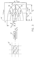
- the multiple quantizers selected by the quantizer select module 48 are arranged in a elliptically partitioned configuration as shown in FIG. 3.
- Each quantizer Q n is chosen from a set of quantizers 10' based on the local statistics ⁇ k , ⁇ k of an n x m blocked neighborhood 12' of scaled residual data S ⁇ ij , where the subscript k indicates the k th block of residual image data.
- the mean ⁇ k and standard deviation, ⁇ k are computed (14') for each block of scaled data.
- the absolute value of the mean and standard deviation are clipped to respective maximum values as shown in FIG. 3. These statistics are employed to index a quantizer Q n .
- the zeroth quantizer Q 0 represent a run length quantizer which is selected when the Run_flag is ON. This run length occupies a rectangular portion of the quantizer space as shown in FIG. 3. The remainder of the quantizer space is elliptically and angularly partitioned in the space of the local statistics ⁇ , ⁇ . Each elliptical segment represents a single quantizer Q n . The number of reconstruction levels for each quantizer is shown in parenthesis next to the quantizer designation in FIG. 3. The quantizer space outside the elliptically partioned region, designated Quantizer Q 8 , in FIG. 3 represents the lossless compression process. If quantizer Q 8 is designated by the quantizer select module 48, switch 26 selects the lossless compression process 18.
- a specific quantizer Q n in the elliptically partitioned quantizer space is selected as shown in FIG. 4.
- E i represents the position of ⁇ k and ⁇ k relative to the radii of the i th ellipse ⁇ bi and ⁇ gi .
- the corresponding angular segment is selected (76) using the following equation:
- the calculated angular position, ⁇ k is compared to the angular segment thresholds 78 (see FIG. 3) to determine the specific quantizer Q n that will be used for processing the blocked neighborhood of data.
- the angular thresholds 78 are ⁇ 15 degrees with respect to the horizontal axis ⁇ .
- the elliptical quantizer partitioning provides a more flexible method of categorizing blocked image data than the circularly symmetric quantizer partitioning deployed in the prior art technique.
- the elliptical partitioning facilitates segmentation of the quantizer space with independent control of both the mean ⁇ and standard deviation ⁇ of the block.
- the scale factor S discussed above directly affects the quantizer selection process. Scale factors less than one effectively reduce the mean and standard deviation statistics, whereas scale factors greater than one increase these local statistics. This results in a lower ⁇ - ⁇ quantizer being selected for scale factors less than one, and a higher ⁇ - ⁇ quantizer being selected for scale factors greater than one. Since the innermost quantizers have fewer reconstruction levels, a scale factor below one will reduce the effective bit-rate, whereas a scale factor above one will increase the effective bit-rate.
- the original pixel values, previously reconstructed pixel values, and a quantizer select (Q sel ) signal are fed into a run select module 50 to determine whether the current block of image pixel values are to be classified as a low activity region.
- the run select module 50 generates a run_flag signal which is ON if the block is classified as low activity image region and is OFF otherwise.
- the run select module 50 also specifies an image mean tracking signal (DC_track) which is used to track the mean level of an image for blocks that are classified as low activity image blocks.
- the quantizer select module 48 responds to the scaled difference pixel values S[ ⁇ ij ], and the run_flag signal for the block currently being processed and generates the quantizer select signal (Q sel ).
- the Q sel signal specifies the specific quantizer used.
- a run quantizer is selected if the run_flag generated by the run select module 50 is ON.
- the specific quantizer utilized for quantizing is specified by the quantizer select signal Q sel which is passed to a subsample mask module 52 and a quantizer module 54.
- the subsample mask module 52 specifies a subsample mask bit pattern for the selected quantizer (Q sel ) corresponding to the spatial location of pixel values within a block of data.
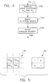
- the subsample mask 80 is an nxm (e.g. 2x2) binary bit pattern representing corresponding locations in an nxm block 82 of image scaled image difference pixel values S ⁇ ij .
- the bit pattern value in the subsample mask 80 is a "one”
- the corresponding scaled image difference pixel value in the block 82 is quantized by quantizer 54 and the quantized symbol Q symbol is transmitted.
- the bit pattern value in the subsample mask 80 is a "zero”
- the corresponding scaled image difference pixel value in the block 82 is set to an average quantization level and no quantized symbol Q symbol is transmitted.
- FIG. 2x2 binary bit pattern representing corresponding locations in an nxm block 82 of image scaled image difference pixel values S ⁇ ij .
- Subsample mask bit patterns having zeros are chosen by the system designer for quantizers where there is low activity in the image, such as quantizers Q 1 and Q 2 where the mean and standard deviation of the image difference pixel values are closer to zero (see FIG. 3).
- quantizers representing high activity in the image all the bits in the subsample mask 80 are set to one.
- the quantizer select 48 is selecting a run quantizer (i.e. very low image activity)
- the bits in the subsample mask 80 are all set to zero.
- Quantizer 54 responds to Q sel and subsample mask signals to appropriately quantize scaled difference pixel values S[ ⁇ ij ] (again, not necessarily the same as the difference pixel value produce by subtractors 34 and 44 described above). Quantizer 54 produces both a symbol (Q symbol ) representing the quantized difference pixel value and the quantized difference pixel value itself (S[ ⁇ ' ij ]). If the quantization error in the quantized difference pixel value exceeds a predetermined amount, a unique Q symbol is generated by the quantizer 54. Q symbol is fed back to the quantizer select module 48, and when the unique Q symbol is detected by the Quantizer select module 48, it produces an output Q sel representing the lossless process, designated by Q8 in FIG. 3. If a block in a run is targeted for DC tracking, a DC_track symbol in place of the normally transmitted Q symbol is transmitted from the quantizer 54.
- the Q sel signal and the Q symbol signal comprise the ENC3 encoder command signals discussed with respect to FIG. 1.
- the quantized difference pixel value (S[ ⁇ ' ij ]) is input to an adder 56 along with predicted pixel value S[p ij ] to produce a scaled reconstructed pixel value S[I' ij ].
- the scaled reconstructed pixel value S[I' ij ] is supplied to a multiplier 58 where it is multiplied by the inverse 1/S of the scale factor to produce blocks of reconstructed pixel values [I' ij ], which are marked for storage in memory buffer 16.
- the scaled reconstructed pixel values S[I' ij ] are also supplied to a predictor 60.
- Predictor 60 also receives scaled previously reconstructed pixel values S[I' ij ], to produce scaled predicted pixel values S[P ij ].
- the scaled reconstructed pixel values are formed by multiplier 62, which receives previously reconstructed pixel values I' ij and scale factor S.
- the scaled predicted pixel values S[P ij ] are subtracted from scaled original pixel values S[I ij ] in subtractor 64 to produce scaled difference pixel values S[ ⁇ ij ].
- the scaled original pixel values S[I ij ] are formed in a multiplier 66 by multiplying the original pixel values [I ij ] by the scale factor S.
- Switch 26 receives the configuration control signal CCM, and encoder signals ENC1 and ENC3. Based on the CCM signal switch 26 passes the appropriate encoder signals to encoder 28. Switch 26 also passes the mode signal CCM and the user specified scale factor S to the encoder 28. If the CCM signal is set to select the ENC3 signals and if Q sel indicates quantizer Q 8 , Q sel is transmitted as overhead, the prefix signal from ENC1 is passed as the Residual, the Code signal from ENC1 is passed as LLCode, and LLflag is turned ON. Switch 26 produces an overhead signal representing either R block or Q sel based on the mode indicated by the CCM signal.
- Switch 26 also produces a residual signal representing either the prefix symbol from the lossless processor 18 or the Q symbol from the lossy compressor 22.
- Switch 26 produces a signal LLflag indicating that data being passed to the encoder 28 is from a lossless processor. If the lossless flag LLflag is ON, indicating a lossless process, then the code signals from the lossless processor 18 are passed as LLcode signals to the encoder 28.
- Switch 26 also enables the memory buffer 16 via enable signal ME to receive marked reconstructed pixel data from the processor or compressor sending encoder signals to the encoder 28 via switch 26.
- Encoder 28 receives the encoder command signals from the switch 26, Huffman encodes the overhead and residual signals, and encodes the lossless code LLcode with a fixed bit pattern.
- the encoder 28 encodes the mode signal CCM and the scale factor S as a fixed bit-length code preceded by a unique marker code.
- the set of Huffman codes used for encoding the residual signal is chosen based on the overhead signal.
- the bit length of each LLcode is determined by the residual signal. For blocks of data which are designated as low activity regions, run-length encoding may be used. During a run, the DC tracking bias is encoded using a Huffman code.
- the range values (R block ) in the overhead signal are conditionally encoded based on the previous R block values.
- Table 3 shows the bit lengths of the Huffman codes used to encode these range values. The dashed line at 1-1 in table 3 indicates that this combination of current and previous range values has a high degree of probability and will be run length encoded.
- Table 4 shows the bit length of the Huffman code used to encode a prefix value for a selected range value for a block. A blank entry in the table indicates a combination that will not occur.
- Table 4 Selected R block Prefix value 0 1 2 3 4 5 6 7 8 0 0 1 2 1 2 2 3 2 2 2 3 3 4 4 3 2 2 2 4 6 5 4 3 2 2 2 7 7
- the code values LLcode from the classifier 38 in the lossless processor 18 are encoded using a fixed bit-length code.
- the length of the code is the same as that shown in the third column of Table 1.
- the quantizer select values (Q sel ) in the overhead signal are conditionally encoded based on the previous Q sel values.
- Table 5 shows the bit lengths of the Huffman codes used to encode these quantizer select values. The dashed line at 0-0 in table 5 below indicates that this combination of current and previous quantizer select values has a high degree of probability and will be run length encoded.
- Table 6 shows the bit length of the Huffman code used to encode a Q symbol value for a selected quantizer select value for a block. A blank entry in the table indicates a combination that will not occur.
- Table 6 Current Q sel Q symbol 0 1 2 3 4 5 6 7 8 9 10 11 12 13 14 15 0 0 1 3 3 2 2 3 3 2 7 7 4 3 2 3 3 3 3 5 7 7 3 8 8 6 4 3 2 2 3 3 5 8 8 4 8 8 5 3 3 2 2 3 4 6 8 8 5 14 12 11 10 9 8 7 6 5 4 4 4 4 4 4 4 4 4 6 14 13 12 10 9 7 6 6 5 5 4 3 3 3 3 3 7 16 16 16 13 13 11 11 10 9 9 8 7 6 5 4 4 8 11 10 6 5 4 3 2 2 7 Current Q sel Q symbol 16 17 18 19 20 21 22 23 24 25 26 27 28 29 30 31 0 1 2 3 4 5 4 4 4 4 4 4 4 4 5 6 7 8 9 10 10 13 14 6 4 4 5 6 7 8 8 0 10 10 12 13 13 15 15 7 3 3
- the values in table 6 above represent the Huffman code lengths used to encode the prefix value from ENC1 which is sent as the Residual signal.
- the output of encoder 28 is a bitstream of compressed overhead and image data.
- the blocked image pixel values [I ij ] are multiplied by the scale factor S in multiplier 84 to produce scaled blocked image pixel values S[I ij ].
- Previously reconstructed image pixel values I' ij are multiplied by the scale factor S in multiplier 86 to produce scaled reconstructed image pixel values SI' ij .
- the scaled reconstructed image pixel values SI' ij are supplied to a predictor 88 which produces blocks of predicted scaled pixel value S[P ij ], which are fed back to the predictor 88 and subtracted from the blocks of scaled image pixel values in subtractor 90 on a pixel by pixel basis to form blocks of scaled image difference pixel values S[ ⁇ ij ].
- the quantizer select signal Q sel is delayed by one block processing period by delay 92 to produce a previous quantizer select signal.
- the previous quantizer select signal is supplied to a DC track enabler 94. Referring to FIG. 7, the DC track enabler tests to determine whether the previous quantizer select signal indicates a run (96).
- an internal counter num_runs that keeps track of the number of blocks in a run is set to one (98). If the previous quantizer select signal indicates a run, the internal counter is incremented by one (100). Next, the internal counter is checked (102) to determine whether the count num_runs is a multiple of a user defined integer (e.g. 4) representing the number of blocks that are passed before checking for a DC track bias. If the count is a multiple of the user defined integer, a DC track flag (track_flag) is turned ON (104), otherwise, the DC track flag is turned OFF (106). Returning to FIG. 6, the DC track flag is supplied to a reconstruction error calculator 108 and a DC track bias calculator 110.
- a user defined integer e.g. 4
- the DC track flag is also sent to the quantizer 54.
- the reconstruction error calculator 108 and the DC track bias calculator 110 are enabled.
- the reconstruction error calculator 108 and the DC track bias calculator 110 are bypassed.
- the reconstruction error calculator 108 receives a block of sampled image pixel difference signals S[ ⁇ ij ] and calculates a reconstruction error R error as follows:
- the DC track bias calculator 110 receives the reconstruction error R error and calculates a bias ⁇ and a DC_track signal which corresponds to the calculated bias.
- the bias ⁇ is determined as follows: where, ⁇ 0 is a positive constant (e.g. 4). DC_Thresh[0] is equal to - ⁇ 0 /2; and DC_Thresh[1] is equal to + ⁇ 0 /2.
- ⁇ can take on any one of three values determined by two thresholds. This concept can be generalized so that ⁇ can take on any one of any number N of values determined by N-1 thresholds.
- the DC_track signal is a symbol representing ⁇ , for example, 01 when ⁇ is 0, 00 when ⁇ is - ⁇ 0 , and 10 when ⁇ is + ⁇ 0 .
- the DC_track signal is supplied to the quantizer 54 (see FIG. 2). IF the DC track flag is ON, the DC_track signal is transmitted by the quantizer 54 as Q symbol and ⁇ corresponding to the DC_track signal is passed in place of the quantized difference pixel values S[ ⁇ ' ij ].
- ⁇ is added to the scaled difference pixel values S[ ⁇ ij ] in adder 112 to produce biased scaled difference pixel values.
- the biased scaled difference pixel values are supplied to a run classifier 114.
- Run classifier 114 determines whether the block should be classified as a run block as shown in FIG. 8.
- the mean and standard deviation of the block of biased scaled difference values is calculated (116).
- the statistics of the block are then compared to user specified run criteria ⁇ run and ⁇ run (118). If the statistics meet the criteria for a run, the run_flag is turned ON (120), otherwise it is turned OFF (122).
- the run flag is supplied to the quantizer select module 48 (see FIG. 2).
- the compressed bit stream is received from storage or transmission and is decoded in a decoder 126 to produce a compression configuration mode signal CCM, a scale factor S, an overhead, residual, LLflag, and LLcode signals by performing the inverse of the encoding technique (e.g. Huffman encoding) implemented by encoder 28.
- the signals produced by the decoder 126 are supplied to a symbol reconstruct module 128, where either the lossy (Q symbol ) or lossless (LL symbol ) symbols are reconstructed depending on the value of the mode signal CCM.
- a process that is the inverse of the classifier 38 is performed.
- the lossy symbol is simply the residual signal provided by the decoder 126.
- the symbols from the symbol reconstruct module 128 are supplied to a pixel reconstruct module 130, which reconstructs the image difference pixel values [ ⁇ ij ] by performing the inverse process of symbolizer 36 for the lossless symbols.
- the scaled difference pixel values S[ ⁇ ' ij ] are reconstructed by a look up table that is addressed by the symbol value.
- the reconstructed image difference pixel values are added to predicted image pixel values produced by predictor 132 in adder 134 to produce decompressed image signals S[I' ij ] (from lossy compression) or [I' ij ] (form lossless compression).
- the predictor 132 is functionally equivalent to the predictors 32 and 60 in the compressor.
- the decompressed image signal from the lossy compressor are multiplied by the inverse of the scale factor 1/S in multiplier 136.
- the block adaptive DPCM compression system described above may be implemented on a general purpose digital computer, or in custom digital processing hardware or firmware.
- lossless processor 18 and encoder 28 may be used as a stand alone system for lossless compression.
- lossy compressor 22 and encoder 28 may be used as a stand alone system for lossy compression.
Landscapes
- Engineering & Computer Science (AREA)
- Multimedia (AREA)
- Signal Processing (AREA)
- Physics & Mathematics (AREA)
- Discrete Mathematics (AREA)
- General Physics & Mathematics (AREA)
- Compression Or Coding Systems Of Tv Signals (AREA)
- Compression, Expansion, Code Conversion, And Decoders (AREA)
- Compression Of Band Width Or Redundancy In Fax (AREA)
Abstract
Description
- The invention relates generally to the field of digital image processing, and in particular to a method for adaptively compressing residual digital image data in a differential pulse code modulation (DPCM) system.
- A DPCM system for compressing a digital image signal generally includes a predictor, a quantizer, and an encoder. The predictor serves to transform the digital image signal into a residual signal space. The residual signal is simply the mathematical difference between the original pixel values in the digital image signal and corresponding predicted pixel values produced by the system.
- A block adaptive quantization strategy was developed by Sullivan et al. for a prediction-based compression technique, see U.S. Patent No. 4,885,636; issued Dec. 5, 1989 to J.R. Sullivan, and U.S. Patent No. 5,287,200 issued Feb. 15, 1994 to J.R. Sullivan and C.M. Smith. The quantizer systems disclosed by Sullivan et al. include multiple quantizers which are arranged in a radial (circularly symmetric) configuration as shown in FIG. 10. A specific quantizer Qn is chosen from a set of
quantizers 10 based on the local statistics µk,σk of an n x m blockedneighborhood 12 of residual data Δij, where the subscript k indicates the kth block of residual image data. The mean, µk, and standard deviation, σk, are computed (14) for each block ofdata 10; these statistics index a quantizer Qn which is tuned to the local statistics for that blocked neighborhood. The statistics are computed as follows:
- The residual signal, Δij, is the mathematical difference between the original image pixel, xij, value and its corresponding predicted value, pij.

- So far the discussion has been limited to lossy compression techniques. A prediction based numerically lossless compression algorithm bypasses the quantization process and achieves compression by directly encoding the residual data. Encoding techniques such as Huffman and arithmetic coding can be used to losslessly encode the residual image data. These encoding techniques may also be used to encode the quantized residual image data. For achieving very low bit rates, Sullivan et al. disclose the technique of deciding whether a block of residual data is in a run of blocks having near zero residual values, and run-length encoding such blocks.
- The radial, circularly symmetric partitioning of quantizer space in the DPCM encoding technique disclosed by Sullivan et al. limits the ability to tune the quantizer selection process independently for both the mean and standard deviation of the local blocks.
- In the run-length encoding technique disclosed by Sullivan et al., error can accumulate during a run, causing a bias in the reconstructed digital image signal. This accumulated error can result in the premature termination of a run thereby decreasing the effectiveness of the compression technique.
- It is the object of the present invention to overcome the shortcomings noted above and to further improve the prior art DPCM encoding technique.
- The object is achieved according to the present invention by providing a block adaptive differential pulse code modulation (DPCM) system including a lossless DPCM processor responsive to blocks of pixel values for producing encoder command signals; a lossy DPCM compressor responsive to blocks of pixel values for producing encoder command signals; an encoder for receiving encoder command signals and producing a compressed encoded bit stream; and a switch responsive to a compression configuration signal and to the encoder command signals from the lossy compressor for selectively passing the encoder command signals from the lossless processor or the lossy compressor to the encoder.
- The block adaptive differential pulse code modulation (DPCM) compression system according to the present invention is capable of achieving compression rates ranging from low bit rates (less than 1.0 bits per pixel) to numerically lossless compression .
- According to a further aspect of the present invention, an improved adaptive quantizer employs an elliptically partitioned quantizer space which allow the quantizer selection to be tuned independently for both mean and standard deviation of the blocks. This allows for more efficient design of a quantizer space and the corresponding quantizers within the quantizer space.
- According to another aspect of the present invention, the quantized residual data is subsampled during the quantization step in low activity image regions and the unsampled data is discarded to further increase compression. For image blocks that are classified as run blocks, the accumulated error is tracked and a bias is introduced to offset the error when the error exceeds a certain threshold. This results in a greater number of sequential blocks being classified as in a run, thereby increasing the compression of the data.
- According to a still further aspect of the present invention, the digital image data and residual data may be multiplied by a scale factor prior to quantization. The scale factor governs the amplitude of the residual signal which ultimately results in controlling the compressibility of the data. This scale factor can be user specified to vary the compression rate. Additionally, the user can manually specify a desired processing configuration to select a particular processing path, lossy or lossless. Alternatively, the processing configuration is automatically selected by a rate controller as a function of the local compression rate. A suitable rate controller for controlling the compression rate is disclosed in copending U.S. patent application Serial No. (409,571) entitled "Data Compression Rate Control Method and Apparatus" by Douglas W. Couwenhoven et al., filed on March 24, 1996. Both the user specification or automatic control of a processing configuration mode and a scale factor provide the means for rate controlling the processing system according to the needs of the user.
- These and other aspects, objects, features and advantages of the present invention will be more clearly understood and appreciated from a review of the following detailed description of the preferred embodiments and appended claims, and by reference to the accompanying drawings.
-
- FIG. 1 is a block diagram showing a DPCM compression system having lossless and lossy compression paths according to the present invention;
- FIG. 2A and 2B represent is a detailed block diagram showing a preferred embodiment of the DPCM compression system shown in FIG. 1;
- FIG. 3 is a schematic diagram illustrating an elliptically partitioned quantization space employed in the lossy compression path;
- FIG. 4 is a flow chart showing the quantizer selection process employed in the lossy compression path of the present invention;
- FIG. 5 is a schematic diagram illustrating the block structure and corresponding subsample mask used in the lossy compression path according to one aspect of the present invention;
- FIG. 6 is a block diagram illustrating the run select and DC tracking module shown in FIG. 2;
- FIG. 7 is a flow chart showing the DC tracking enabling logic performed by the module shown in FIG. 6;
- FIG. 8 is a flow chart showing the logic performed by the run classifier shown in FIG. 2;
- FIG. 9 is a block diagram illustrating a DPCM decompressor according to the present invention; and
- FIG. 10 is a schematic diagram illustrating a circularly partitioned quantization space employed in a lossy compression technique of the prior art.
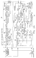
- The hardware block diagram shown in FIG. 1 gives an overview of the block adaptive differential pulse code modulation (DPCM) compressor according to the present invention. When blocks of data are discussed herein, the symbol for the data will be enclosed in square brackets "[]". Blocks of input image data [Iij] and previously reconstructed image data I'ij which is stored in and read from a
common memory buffer 16 are passed to a firstlossless processor 18, a secondlossless processor 20, a firstlossy compressor 22, and a secondlossy compressor 24. Thelossless processors lossy compressors switch 26. Thisswitch 26 is responsive to a compression configuration mode signal CCM for selecting specific encoder command signals to be passed to the encoder. Theswitch 26 is further responsive to the contents of the encoder command signals for determining which specific encoder command signal gets passed to anencoder 28, thereby selectively overriding the configuration mode signal when necessary to maintain an upper bound on the quantization error resulting from a lossy compression. Theencoder 28 receives the passed encoder command signal ENCx for encoding processed residual image data into a compressed bit stream. Theswitch 26 also generates a processor signal indicating the processing path presently being employed. This processor signal activates amemory buffer 16 for storing reconstructed image data from the presently employed processing path. The compressed bit stream produced by the compressor may be stored or transmitted as is well known in the art. - A more detailed block diagram of the workings of a block adaptive lossless processor and a block adaptive lossy compressor is provided in FIG. 2A and 2B, where parts similar to those in Fig. 1 are similarly numbered. The input image pixel values Iij are formed into blocks [Iij] by block former 30.
Block 18 in FIG. 2A is a more detailed block diagram of a lossless processor. In thelossless processor 18, blocks of pixel values [Iij], and reconstructed pixel values I'ij are received and fed to apredictor 32 for generating a block of predicted pixel values [pij]. A suitable predictor is shown and described in EP-A-95420290.9, entitled "Digital Image Processor" by Bhavan R. Gandhi et al. - The original pixel values are marked for storage in
memory buffer 16. Each predicted pixel value in the block [pij], is subsequently subtracted from the corresponding original pixel value in the block [Iij], in asubtractor 34 to form difference pixel values, [Δij]. The predicted pixel values [pij] and the corresponding difference pixel values [Δij] are fed to asymbolizer 36 which generates a lossless symbol, LLsymbol, corresponding to the difference signal. In an eight-bit system, LLsymbol can take any value between 0 and 255. The lossless symbol, LLsymbol, is then fed to aclassifier 38 which groups together symbols with similar probabilities.Classifier 38 identifies the group of which LLsymbol is a member and a symbol within the group. The group is represented by a prefix value, and a corresponding code value representing the symbol within the group. The first column of Table 1 lists the groups of LLsymbol values and the second column shows the corresponding prefix values for each group. The third column lists the number of bits in the code value. The code values are calculated by subtracting the minimum symbol value in the group from the actual symbol value.Table 1. Lossless Symbol Group Prefix # of Code Bits 0 0 0 1-2 1 1 3-6 2 2 7-14 3 3 15-30 4 4 31-62 5 5 63-126 6 6 127-254 7 7 255 8 0 Table 2 Maximum Prefix Range Selection (Rblock) 0 0 1 1 2 1 3 2 4 2 5 3 6 4 7 4 8 4 - The prefix and code values generated by the
classifier 38 are fed to theswitch 26. Finally, a rangeselect module 40 responding to prefix values for each symbol in an N x M pixel block is used to generate the maximum prefix value in the N x M pixel block. This maximum prefix value for the block, denoted as Rblock, is also fed to theswitch 26. Table 2 lists the maximum prefix values and corresponding Rblock values. In the preferred embodiment, there are five Rblock values taking on values between zero and four. In summary,lossless processor 18 generates an Rblock value for an N x M block, and corresponding prefix and code values for each pixel within the N x M block, all of which are fed to theswitch 26. These three values comprise the encoder command signals ENC1. - A more detailed block diagram of a
lossy compressor 22 is also shown in FIG. 2A. Thelossy compressor 22 receives blocks of original image pixel values, [Iij], previously reconstructed pixel values I'ij and a scale factor S. Scale factor S can be user specified, or alternatively provided by a rate controller (not shown) that responds to a memory buffer level and rate of fill signal. Thelossy compressor 22 produces a quantizer select signal Qsel, quantized symbol data (Qsymbol), and blocks of reconstructed pixel data ([I'ij]). Original pixel values [Iij] and previously reconstructed pixel values I'ij, are input to apredictor 42 which produces a predicted pixel value pij (not necessarily the same as the predicted pixel value produced bypredictor 32 described above) corresponding to the current original pixel value. The predicted pixel value is subsequently subtracted from the original pixel value bysubtractor 44 to produce a difference pixel value Δij (again, not necessarily the same as the difference pixel value produce bysubtractor 34 described above) for each pixel in a N x M block of pixels. Each of the difference pixel values are multiplied a scale factor S bymultiplier 46. The scaled difference pixel values S[Δij] are further processed by a quantizerselect module 48. - According to a preferred embodiment of the invention, the multiple quantizers selected by the quantizer
select module 48 are arranged in a elliptically partitioned configuration as shown in FIG. 3. Each quantizer Qn is chosen from a set of quantizers 10' based on the local statistics µk, σk of an n x m blocked neighborhood 12' of scaled residual data SΔij, where the subscript k indicates the kth block of residual image data. The mean µk and standard deviation, σk, are computed (14') for each block of scaled data. The absolute value of the mean and standard deviation are clipped to respective maximum values as shown in FIG. 3. These statistics are employed to index a quantizer Qn. The zeroth quantizer Q0 represent a run length quantizer which is selected when the Run_flag is ON. This run length occupies a rectangular portion of the quantizer space as shown in FIG. 3. The remainder of the quantizer space is elliptically and angularly partitioned in the space of the local statistics µ,σ. Each elliptical segment represents a single quantizer Qn. The number of reconstruction levels for each quantizer is shown in parenthesis next to the quantizer designation in FIG. 3. The quantizer space outside the elliptically partioned region, designated Quantizer Q8, in FIG. 3 represents the lossless compression process. If quantizer Q8 is designated by the quantizerselect module 48,switch 26 selects thelossless compression process 18. A specific quantizer Qn in the elliptically partitioned quantizer space is selected as shown in FIG. 4. First the local statistics µk and σk are computed (72). Next, the ith elliptical region for each block, indexed by k, is selected (74) if:

- Once the elliptical region is selected, the corresponding angular segment is selected (76) using the following equation:

- Outside the quantizer Q0, the calculated angular position, Φk, is compared to the angular segment thresholds 78 (see FIG. 3) to determine the specific quantizer Qn that will be used for processing the blocked neighborhood of data. In the preferred embodiment, the
angular thresholds 78 are ±15 degrees with respect to the horizontal axis σ. - The elliptical quantizer partitioning provides a more flexible method of categorizing blocked image data than the circularly symmetric quantizer partitioning deployed in the prior art technique. The elliptical partitioning facilitates segmentation of the quantizer space with independent control of both the mean µ and standard deviation σ of the block.
- Since the quantizer selection process is operating on scaled block data, the scale factor S discussed above directly affects the quantizer selection process. Scale factors less than one effectively reduce the mean and standard deviation statistics, whereas scale factors greater than one increase these local statistics. This results in a lower µ-σ quantizer being selected for scale factors less than one, and a higher µ-σ quantizer being selected for scale factors greater than one. Since the innermost quantizers have fewer reconstruction levels, a scale factor below one will reduce the effective bit-rate, whereas a scale factor above one will increase the effective bit-rate.
- In conjunction with the above described processing, the original pixel values, previously reconstructed pixel values, and a quantizer select (Qsel) signal are fed into a run
select module 50 to determine whether the current block of image pixel values are to be classified as a low activity region. The runselect module 50 generates a run_flag signal which is ON if the block is classified as low activity image region and is OFF otherwise. The runselect module 50 also specifies an image mean tracking signal (DC_track) which is used to track the mean level of an image for blocks that are classified as low activity image blocks. The quantizerselect module 48 responds to the scaled difference pixel values S[Δij], and the run_flag signal for the block currently being processed and generates the quantizer select signal (Qsel). The Qsel signal specifies the specific quantizer used. A run quantizer is selected if the run_flag generated by the runselect module 50 is ON. The specific quantizer utilized for quantizing is specified by the quantizer select signal Qsel which is passed to asubsample mask module 52 and aquantizer module 54. Thesubsample mask module 52 specifies a subsample mask bit pattern for the selected quantizer (Qsel) corresponding to the spatial location of pixel values within a block of data. - As shown in FIG. 5, the
subsample mask 80 is an nxm (e.g. 2x2) binary bit pattern representing corresponding locations in annxm block 82 of image scaled image difference pixel values SΔij. When the bit pattern value in thesubsample mask 80 is a "one", the corresponding scaled image difference pixel value in theblock 82 is quantized byquantizer 54 and the quantized symbol Qsymbol is transmitted. When the bit pattern value in thesubsample mask 80 is a "zero", the corresponding scaled image difference pixel value in theblock 82 is set to an average quantization level and no quantized symbol Qsymbol is transmitted. In the example of the subsample mask shown in FIG. 5, only half of the quantized scaled image difference pixel values are transmitted by thequantizer 54 via the Qsymbol signal. This has the effect of increasing the compression ratio by a factor of two for data blocks quantized with a quantizer having a subsample mask with half the bits set to zero. - Subsample mask bit patterns having zeros are chosen by the system designer for quantizers where there is low activity in the image, such as quantizers Q1 and Q2 where the mean and standard deviation of the image difference pixel values are closer to zero (see FIG. 3). For quantizers representing high activity in the image, all the bits in the
subsample mask 80 are set to one. When the quantizer select 48 is selecting a run quantizer (i.e. very low image activity), the bits in thesubsample mask 80 are all set to zero. -
Quantizer 54 responds to Qsel and subsample mask signals to appropriately quantize scaled difference pixel values S[Δij] (again, not necessarily the same as the difference pixel value produce bysubtractors Quantizer 54 produces both a symbol (Qsymbol) representing the quantized difference pixel value and the quantized difference pixel value itself (S[Δ'ij]). If the quantization error in the quantized difference pixel value exceeds a predetermined amount, a unique Qsymbol is generated by thequantizer 54. Qsymbol is fed back to the quantizerselect module 48, and when the unique Qsymbol is detected by the Quantizerselect module 48, it produces an output Qsel representing the lossless process, designated by Q8 in FIG. 3. If a block in a run is targeted for DC tracking, a DC_track symbol in place of the normally transmitted Qsymbol is transmitted from thequantizer 54. The Qsel signal and the Qsymbol signal comprise the ENC3 encoder command signals discussed with respect to FIG. 1. - The quantized difference pixel value (S[Δ'ij]) is input to an
adder 56 along with predicted pixel value S[pij] to produce a scaled reconstructed pixel value S[I'ij]. The scaled reconstructed pixel value S[I'ij] is supplied to amultiplier 58 where it is multiplied by theinverse 1/S of the scale factor to produce blocks of reconstructed pixel values [I'ij], which are marked for storage inmemory buffer 16. The scaled reconstructed pixel values S[I'ij] are also supplied to apredictor 60.Predictor 60 also receives scaled previously reconstructed pixel values S[I'ij], to produce scaled predicted pixel values S[Pij]. The scaled reconstructed pixel values are formed bymultiplier 62, which receives previously reconstructed pixel values I'ij and scale factor S. - The scaled predicted pixel values S[Pij] are subtracted from scaled original pixel values S[Iij] in
subtractor 64 to produce scaled difference pixel values S[Δij]. The scaled original pixel values S[Iij] are formed in amultiplier 66 by multiplying the original pixel values [Iij] by the scale factor S. -
Switch 26 receives the configuration control signal CCM, and encoder signals ENC1 and ENC3. Based on the CCM signal switch 26 passes the appropriate encoder signals toencoder 28.Switch 26 also passes the mode signal CCM and the user specified scale factor S to theencoder 28. If the CCM signal is set to select the ENC3 signals and if Qsel indicates quantizer Q8, Qsel is transmitted as overhead, the prefix signal from ENC1 is passed as the Residual, the Code signal from ENC1 is passed as LLCode, and LLflag is turned ON.Switch 26 produces an overhead signal representing either Rblock or Qsel based on the mode indicated by the CCM signal.Switch 26 also produces a residual signal representing either the prefix symbol from thelossless processor 18 or the Qsymbol from thelossy compressor 22.Switch 26 produces a signal LLflag indicating that data being passed to theencoder 28 is from a lossless processor. If the lossless flag LLflag is ON, indicating a lossless process, then the code signals from thelossless processor 18 are passed as LLcode signals to theencoder 28.Switch 26 also enables thememory buffer 16 via enable signal ME to receive marked reconstructed pixel data from the processor or compressor sending encoder signals to theencoder 28 viaswitch 26. -
Encoder 28 receives the encoder command signals from theswitch 26, Huffman encodes the overhead and residual signals, and encodes the lossless code LLcode with a fixed bit pattern. Theencoder 28 encodes the mode signal CCM and the scale factor S as a fixed bit-length code preceded by a unique marker code. The set of Huffman codes used for encoding the residual signal is chosen based on the overhead signal. The bit length of each LLcode is determined by the residual signal. For blocks of data which are designated as low activity regions, run-length encoding may be used. During a run, the DC tracking bias is encoded using a Huffman code. - When LLflag is ON (i.e. the lossless process is being employed) the range values (Rblock) in the overhead signal are conditionally encoded based on the previous Rblock values. Table 3 shows the bit lengths of the Huffman codes used to encode these range values. The dashed line at 1-1 in table 3 indicates that this combination of current and previous range values has a high degree of probability and will be run length encoded.


- Table 4 shows the bit length of the Huffman code used to encode a prefix value for a selected range value for a block. A blank entry in the table indicates a combination that will not occur.
Table 4 Selected R block Prefix value 0 1 2 3 4 5 6 7 8 0 0 1 2 1 2 2 3 2 2 2 3 3 4 4 3 2 2 2 4 6 5 4 3 2 2 2 7 7 - Also, when LLflag is ON, the code values LLcode from the
classifier 38 in thelossless processor 18 are encoded using a fixed bit-length code. The length of the code is the same as that shown in the third column of Table 1. - When LLflag is OFF ( i.e. the lossy compressor is being employed) the quantizer select values (Qsel) in the overhead signal are conditionally encoded based on the previous Qsel values. Table 5 shows the bit lengths of the Huffman codes used to encode these quantizer select values. The dashed line at 0-0 in table 5 below indicates that this combination of current and previous quantizer select values has a high degree of probability and will be run length encoded.
Table 5 Previous Q sel Current Q sel0 1 2 3 4 5 6 7 8 0 - 1 4 2 3 7 5 6 7 1 2 1 5 4 3 8 6 7 8 2 5 2 4 2 2 6 4 4 6 3 4 2 4 2 2 6 4 5 6 4 3 2 3 3 2 6 5 4 6 5 6 4 3 3 2 5 3 2 6 6 6 3 4 2 2 5 3 3 6 7 5 2 3 3 2 6 4 3 6 8 5 4 5 4 3 4 3 2 2 - Table 6 shows the bit length of the Huffman code used to encode a Qsymbol value for a selected quantizer select value for a block. A blank entry in the table indicates a combination that will not occur.
Table 6 Current Qsel Qsymbol 0 1 2 3 4 5 6 7 8 9 10 11 12 13 14 15 0 0 1 3 3 2 2 3 3 2 7 7 4 3 2 3 3 3 3 5 7 7 3 8 8 6 4 3 2 2 3 3 5 8 8 4 8 8 5 3 3 2 2 3 4 6 8 8 5 14 12 11 10 9 8 7 6 5 4 4 4 4 4 4 4 6 14 13 12 10 9 7 6 6 5 5 4 3 3 3 3 3 7 16 16 16 13 13 11 11 10 9 9 8 7 6 5 4 4 8 11 10 6 5 4 3 2 2 2 7 Current Qsel Qsymbol 16 17 18 19 20 21 22 23 24 25 26 27 28 29 30 31 0 1 2 3 4 5 4 4 4 4 4 4 4 5 6 7 8 9 10 10 13 14 6 4 4 5 6 6 7 8 8 0 10 10 12 13 13 15 15 7 3 3 3 3 3 4 4 5 6 7 8 10 11 13 14 16 8 - When Qsel equals 8, indicating the selection of the lossless processor, the values in table 6 above represent the Huffman code lengths used to encode the prefix value from ENC1 which is sent as the Residual signal.
- Although Huffman and run-length coding techniques are presently preferred, other encoding techniques may be employed such as arithmetic coding within the spirit and scope of the present invention. The output of
encoder 28 is a bitstream of compressed overhead and image data. - Referring now to FIG. 6, the run
select module 50 will be described in further detail. The blocked image pixel values [Iij] are multiplied by the scale factor S inmultiplier 84 to produce scaled blocked image pixel values S[Iij]. Previously reconstructed image pixel values I'ij are multiplied by the scale factor S inmultiplier 86 to produce scaled reconstructed image pixel values SI'ij. The scaled reconstructed image pixel values SI'ij are supplied to apredictor 88 which produces blocks of predicted scaled pixel value S[Pij], which are fed back to thepredictor 88 and subtracted from the blocks of scaled image pixel values insubtractor 90 on a pixel by pixel basis to form blocks of scaled image difference pixel values S[Δij]. The quantizer select signal Qsel is delayed by one block processing period bydelay 92 to produce a previous quantizer select signal. The previous quantizer select signal is supplied to a DC track enabler 94. Referring to FIG. 7, the DC track enabler tests to determine whether the previous quantizer select signal indicates a run (96). If the previous quantizer select signal does not indicate a run, an internal counter num_runs that keeps track of the number of blocks in a run is set to one (98). If the previous quantizer select signal indicates a run, the internal counter is incremented by one (100). Next, the internal counter is checked (102) to determine whether the count num_runs is a multiple of a user defined integer (e.g. 4) representing the number of blocks that are passed before checking for a DC track bias. If the count is a multiple of the user defined integer, a DC track flag (track_flag) is turned ON (104), otherwise, the DC track flag is turned OFF (106). Returning to FIG. 6, the DC track flag is supplied to areconstruction error calculator 108 and a DCtrack bias calculator 110. The DC track flag is also sent to thequantizer 54. When the DC track flag is ON, thereconstruction error calculator 108 and the DCtrack bias calculator 110 are enabled. When the DC track flag is OFF, thereconstruction error calculator 108 and the DCtrack bias calculator 110 are bypassed. - The
reconstruction error calculator 108 receives a block of sampled image pixel difference signals S[Δij] and calculates a reconstruction error Rerror as follows:
- The DC
track bias calculator 110 receives the reconstruction error Rerror and calculates a bias β and a DC_track signal which corresponds to the calculated bias. The bias β is determined as follows:
quantizer 54 as Qsymbol and β corresponding to the DC_track signal is passed in place of the quantized difference pixel values S[Δ'ij]. - β is added to the scaled difference pixel values S[Δij] in
adder 112 to produce biased scaled difference pixel values. The biased scaled difference pixel values are supplied to arun classifier 114.Run classifier 114 determines whether the block should be classified as a run block as shown in FIG. 8. In theclassifier 114, the mean and standard deviation of the block of biased scaled difference values is calculated (116). The statistics of the block are then compared to user specified run criteria µrun and σrun(118). If the statistics meet the criteria for a run, the run_flag is turned ON (120), otherwise it is turned OFF (122). The run flag is supplied to the quantizer select module 48 (see FIG. 2). - Referring now to FIG. 9, the decompressor, generally designated 124, for the compressed bit stream will be described. The compressed bit stream is received from storage or transmission and is decoded in a
decoder 126 to produce a compression configuration mode signal CCM, a scale factor S, an overhead, residual, LLflag, and LLcode signals by performing the inverse of the encoding technique (e.g. Huffman encoding) implemented byencoder 28. The signals produced by thedecoder 126 are supplied to a symbol reconstructmodule 128, where either the lossy (Qsymbol) or lossless (LLsymbol) symbols are reconstructed depending on the value of the mode signal CCM. To derive the lossless symbol a process that is the inverse of theclassifier 38 is performed. The lossy symbol is simply the residual signal provided by thedecoder 126. The symbols from the symbol reconstructmodule 128 are supplied to a pixel reconstructmodule 130, which reconstructs the image difference pixel values [Δij] by performing the inverse process ofsymbolizer 36 for the lossless symbols. For the lossy symbols, the scaled difference pixel values S[Δ'ij] are reconstructed by a look up table that is addressed by the symbol value. The reconstructed image difference pixel values are added to predicted image pixel values produced bypredictor 132 inadder 134 to produce decompressed image signals S[I'ij] (from lossy compression) or [I'ij] (form lossless compression). Thepredictor 132 is functionally equivalent to thepredictors scale factor 1/S inmultiplier 136. - The block adaptive DPCM compression system described above may be implemented on a general purpose digital computer, or in custom digital processing hardware or firmware.
- The invention has been described with reference to a preferred embodiment. However, it will be appreciated that variations and modifications can be effected by a person of ordinary skill in the art without departing from the scope of the invention. For example, the
lossless processor 18 andencoder 28 may be used as a stand alone system for lossless compression. Similarly,lossy compressor 22 andencoder 28 may be used as a stand alone system for lossy compression.
Claims (24)
- A block adaptive differential pulse code modulation (DPCM) system for transmitting or storing a digital image signal which are compressed by operating on nxm blocks of pixel values, comprising:a. a first lossless DPCM processor responsive to blocks of pixel values for producing encoder command signals;b. a first lossy DPCM compressor responsive to blocks of pixel values for producing encoder command signals;c. an encoder for receiving encoder command signals and producing a compressed encoded bit stream; andd. a switch responsive to a compression configuration mode signal and to the encoder command signals from the lossy compressor for selectively passing the encoder command signals from the lossless processor or the lossy compressor to the encoder.
- The block adaptive differential pulse code modulation (DPCM) system claimed in claim 1, further comprising:
a. a second lossy DPCM compressor employing a different lossy DPCM compression technique than the first lossy DPCM compressor for producing encoder command signals, the switch selectively passing the encoder command signals from the second lossy DPCM compressor to the encoder in response to the compression configuration mode signal. - The block adaptive differential pulse code modulation (DPCM) system claimed in claim 1, further comprising:
a. a second lossless DPCM processor employing a different lossless DPCM processing technique than the first lossless DPCM processor for producing encoder command signals, the switch selectively passing the encoder command signals from the second lossless DPCM processor to the encoder in response to the compression configuration mode signal. - The block adaptive differential pulse code modulation (DPCM) system claimed in claim 1, wherein the first lossless DPCM processor includes :a. a predictor for receiving a pixel value and previously reconstructed pixel values and producing a predicted pixel value;b. a subtractor for subtracting the predicted pixel value from the pixel value to produce a difference pixel value;c. a symbolizer for generating a lossless symbol value corresponding to the difference pixel value;d. a classifier for receiving the lossless symbol value and producing corresponding prefix and code signals; ande. a range select module for receiving a block of prefix signals and generating a range value for the block.
- The block adaptive differential pulse code modulation (DPCM) system claimed in claim 4, wherein:a. the encoder command signals from the lossless processor include a block of prefix signals identifying a symbol set from a plurality of symbol sets for each location in the block, a block of code values identifying a symbol within the identified symbol set for each location within the block, and a range select signal specifying the maximum prefix signal within the block;b. the encoder command signals from the lossy processor include a quantizer select signal for a block of difference pixel values, and a block of symbols respectively representing a block of quantized difference pixels;c. the switch setting a lossless compression flag when the encoder command signals are being passed from the lossless processor; andd. the encoder produces the compressed encoded bit stream by,when the flag is set, using the range select signal to select an encoder table from a plurality of encoder tables, and using the prefix signals and the code values for selecting code bit patterns from the selected table for each location in the block and encoding the range select signal as overhead information for each block, andwhen the flag is not set, using the quantizer select signal to select an encoder table from a plurality of encoder tables, and using the symbols representing the quantized difference pixels for selecting code bit patterns from the selected table for each location in the block, and encoding the quantizer select signal as overhead information.
- The block adaptive DPCM system claimed in claim 1, wherein the lossy compressor comprises:a. a predictor for receiving a pixel value and previously reconstructed pixel values and producing a predicted pixel value;b. a subtractor for subtracting the predicted pixel value from the pixel value to produce a difference pixel value;c. run select means for receiving a block of pixel values, reconstructed pixel values and a quantizer select signal, and producing a DC track signal representing an offset for the block of pixel values, a track flag indicating whether the block of pixel values is to be DC tracked, and a run flag indicating whether the block of pixel values is classified as a run block;d. quantizer select means responsive to difference pixel values, and the run flag, for forming a corresponding block of difference pixel values and for producing the quantizer select signal for the block;e. a subsample mask responsive to the quantizer select signal for producing a binary mask;f. a quantizer module responsive to the quantizer select signal, the binary mask, the DC track flag, the DC track signal and a second difference signal for producing quantized difference pixel values for each pixel within the block and corresponding symbol values;g. a second predictor responsive to reconstructed pixel values from a current line and a previous line of pixels to produce a second predicted pixel value;h. means for summing the second predicted pixel value and the corresponding quantized difference pixel value to produce the reconstructed pixel value; andi. means for subtracting the second predicted pixel value from the pixel value to produce the second difference pixel value.
- The block adaptive differential pulse code modulation (DPCM) system claimed in claim 6, wherein the lossy compressor further comprises:a. means for scaling the pixel value, the difference pixel value, the reconstructed pixel values from a previous line, by a scaling factor S that can be varied to control the bit rate of the lossy compressor, whereby the bit rate of the lossy compressor is increased with scale factors greater than one and is decreased with scale factors less than one; andb. means for scaling the reconstructed pixel value from a current line by a scaling factor 1/S to produce an unscaled reconstructed pixel value.
- The block adaptive differential pulse code modulation (DPCM) system claimed in claim 1, wherein the lossy compressor further comprises:
a. means for detecting low activity regions in the digital image signal and for generating an encoder command signal instructing the encoder to employ run length coding for the low activity region. - The block adaptive differential pulse code modulation (DPCM) system claimed in claim 6, wherein the set of quantizers in the quantizer module are elliptically partitioned in quantizer selection space.
- An improved block adaptive differential pulse code modulation (DPCM) system for compressing a digital image signal by operating on nxm blocks of pixel values of the type having a lossy compressor employing a set of quantizers, wherein the improvement comprises: the set of quantizers being elliptically partitioned in quantizer selection space.
- An improved block adaptive differential pulse code modulation (DPCM) system for compressing a digital image signal by operating on nxm blocks of pixel values of the type having a lossy compressor employing a set of quantizers, wherein the improvement comprises: run select means for detecting a low activity region in the digital image signal, bypassing the set of quantizers when such low activity region is detected and producing a run length signal for the low activity region.
- The improved block adaptive DPCM claimed in claim 11, wherein the run select means includes:a. predictor means responsive to previously reconstructed pixel values and a previous predicted pixel value for producing a predicted pixel value;b. a subtractor for subtracting each predicted pixel value from each corresponding pixel value in the block to produce difference pixel values;c. means responsive to the track flag and the block of difference pixel values for computing a reconstruction error by calculating the sum of the difference pixel values in the block of difference pixel values;d. means for selecting an offset from a set of operator defined offsets in response to the reconstruction error and the track flag;e. means for adding the selected offset to the difference pixel values in the block to produce offset difference pixel values and the DC track signal;f. means for determining whether a block is classified as a run block in response to the offset difference pixel values; andg. means for determining whether a block should be DC tracked based on a quantizer selected for a previous block and producing the track flag that indicates when the block should be DC tracked.
- An improved block adaptive differential pulse code modulation (DPCM) system for compressing a digital image signal by operating on nxm blocks of pixel values of the type having a lossy compressor employing means for forming a block of difference pixel values, a set of quantizers, means for selecting a quantizer from the set of quantizers for quantizing the difference pixel values within the block, and means for encoding the quantized difference signals, and means for transmitting the encoded quantized difference signals, wherein the improvement comprises:a. subsample mask means responsive to a quantizer selection for producing a binary mask corresponding to the selected quantizer; andb. means for employing the binary mask to selectively quantize, encode, and transmit the quantized difference pixel value when the corresponding mask value is one and when the corresponding mask value is zero, setting the quantized difference signal to a constant user defined value and transmitting nothing.
- The block adaptive DPCM system claimed in claim 13, wherein the user defined value is zero.
- In a block adaptive differential pulse code modulation (DPCM) system for transmitting or storing a digital image signal, a decompressor for reconstructing a digital image from a compressed encoded bit stream produced by a compressor of the type claimed in claim 1, comprising:a. a decoder for receiving the compressed encoded bit stream and reproducing the encoder command signals and the compression configuration mode signal; andb. reconstructing means responsive to the reproduced encoder command signals and the compression configuration mode signal for reconstructing the digital image, the reconstructing means including a first means for reconstructing lossless processed digital image data and a second means for reconstructing lossy compressed digital image data.
- In a block adaptive differential pulse code modulation (DPCM) system, a lossless DPCM processor for compressing a digital image signal having pixel values, comprising:a. a predictor for receiving a pixel value and previously reconstructed pixel values and producing a predicted pixel value;b. a subtractor for subtracting the predicted pixel value from the pixel value to produce a difference pixel value;c. a symbolizer responsive to the predicted pixel value and the corresponding difference pixel value for generating a lossless symbol value corresponding to the difference pixel value;d. a classifier responsive to the lossless symbol value and producing corresponding prefix and code signals;e. a range select module for receiving a block of prefix signals and generating a range value for the block; andf. an encoder responsive to the prefix, code and range values for producing a compressed bit stream representing the digital image.
- The lossless processor claimed in claim 16, wherein said encoder includes a Huffman encoder.
- In a block adaptive differential pulse code modulation (DPCM) system, a lossy DPCM compressor for compressing a digital image signal having pixel values, comprising:a. a predictor for receiving a pixel value and previously reconstructed pixel values and producing a predicted pixel value;b. a subtractor for subtracting the predicted pixel value from the pixel value to produce a difference pixel value;c. run select means for receiving a block of pixel values, reconstructed pixel values and a quantizer select signal, and producing a DC track signal representing an offset for the block of pixel values, a track flag indicating whether the block of pixel values is to be DC tracked, and a run flag indicating whether the block of pixel values is classified as a run block;d. quantizer select means responsive to difference pixel values, and the run flag, for forming a corresponding block of difference pixel values and for producing the quantizer select signal for the block;e. a subsample mask responsive to the quantizer select signal for producing a binary mask;f. a quantizer module responsive to the quantizer select signal, the binary mask, the DC track flag, the DC track signal and a second difference signal for producing quantized difference pixel values for each pixel within the block and corresponding symbol values;g. a second predictor responsive to reconstructed pixel values from a current line and a previous line of pixels to produce a second predicted pixel value;h. means for summing the second predicted pixel value and the corresponding quantized difference pixel value to produce the reconstructed pixel value;i. means for subtracting the second predicted pixel value from the pixel value to produce the second difference pixel value; andj. an encoder responsive to the quantizer select signal and the symbol value corresponding to the quantized difference pixel value for producing a compressed bit steam representing the digital image.
- The lossy DPCM compressor claimed in claim 18, further comprising:a. means for scaling the pixel value, the difference pixel value, and the reconstructed pixel values from a previous line, by a scaling factor S that can be varied to control the bit rate of the lossy compressor, whereby the bit rate of the lossy compressor is increased with scale factors greater than one and is decreased with scale factors less than one; andb. means for scaling the reconstructed pixel value from a current line by a scaling factor 1/S to produce an unscaled reconstructed pixel value.
- The lossy DPCM compressor claimed in claim 17, further comprising:a. means for detecting low activity regions in the digital image signal; andb. means for generating an encoder command signal instructing the encoder to employ run length coding for the low activity region.
- The lossy DPCM system claimed in claim 20, wherein the set of quantizers in the quantizer module are elliptically partitioned in quantizer selection space.
- The lossy DPCM compressor claimed in claim 18, wherein the run select means includes:a. predictor means responsive to previously reconstructed pixel values and a previous predicted pixel value for producing a predicted pixel value;b. a subtractor for subtracting each predicted pixel value from each corresponding pixel value in the block to produce difference pixel values;c. means responsive to the track flag and the block of difference pixel values for computing a reconstruction error by calculating the sum of the difference pixel values in the block of difference pixel values;d. means for selecting an offset from a set of operator defined offsets in response to the reconstruction error and the track flag;e. means for adding the selected offset to the difference pixel values in the block to produce offset difference pixel values and the DC track signal;f. means for determining whether a block is classified as a run block in response to the offset difference pixel values; andg. means for determining whether a block should be DC tracked based on a quantizer selected for a previous block and producing the track flag that indicates when the block should be DC tracked.
- The lossy DPCM compressor claimed in claim 18, wherein the run select means includes:a. subsample mask means responsive to a quantizer selection for producing a binary mask corresponding to the selected quantizer; andb. means for employing the binary mask to selectively quantize, encode, and transmit the quantized difference pixel value when the corresponding mask value is one and when the corresponding mask value is zero, setting the quantized difference signal to a constant user defined value and transmitting nothing.
- The block adaptive DPCM system claimed in claim 23, wherein the user defined value is zero.
Applications Claiming Priority (2)
| Application Number | Priority Date | Filing Date | Title |
|---|---|---|---|
| US41046295A | 1995-03-24 | 1995-03-24 | |
| US410462 | 1995-03-24 |
Publications (3)
| Publication Number | Publication Date |
|---|---|
| EP0734174A2 true EP0734174A2 (en) | 1996-09-25 |
| EP0734174A3 EP0734174A3 (en) | 2003-08-27 |
| EP0734174B1 EP0734174B1 (en) | 2007-08-29 |
Family
ID=23624833
Family Applications (1)
| Application Number | Title | Priority Date | Filing Date |
|---|---|---|---|
| EP96420088A Expired - Lifetime EP0734174B1 (en) | 1995-03-24 | 1996-03-18 | A method for adaptively compressing residual digital image data in a DPCM compression system |
Country Status (4)
| Country | Link |
|---|---|
| US (1) | US5708511A (en) |
| EP (1) | EP0734174B1 (en) |
| JP (2) | JP3749752B2 (en) |
| DE (1) | DE69637223T2 (en) |
Cited By (9)
| Publication number | Priority date | Publication date | Assignee | Title |
|---|---|---|---|---|
| EP0790742A2 (en) * | 1996-02-19 | 1997-08-20 | Fuji Xerox Co., Ltd. | Predictive image coding and decoding system |
| US8509553B2 (en) | 2009-01-07 | 2013-08-13 | Industrial Technology Research Institute | DPCM-based encoder, decoder, encoding method and decoding method |
| WO2014055745A1 (en) * | 2012-10-03 | 2014-04-10 | Broadcom Corporation | 2d block image encoding |
| US9363517B2 (en) | 2013-02-28 | 2016-06-07 | Broadcom Corporation | Indexed color history in image coding |
| US9451250B2 (en) | 2012-10-03 | 2016-09-20 | Broadcom Corporation | Bounded rate compression with rate control for slices |
| US9805442B2 (en) | 2012-10-03 | 2017-10-31 | Avago Technologies General Ip (Singapore) Pte. Ltd. | Fine-grained bit-rate control |
| US9813711B2 (en) | 2012-10-03 | 2017-11-07 | Avago Technologies General Ip (Singapore) Pte. Ltd. | Hybrid transform-based compression |
| US9883180B2 (en) | 2012-10-03 | 2018-01-30 | Avago Technologies General Ip (Singapore) Pte. Ltd. | Bounded rate near-lossless and lossless image compression |
| US9978156B2 (en) | 2012-10-03 | 2018-05-22 | Avago Technologies General Ip (Singapore) Pte. Ltd. | High-throughput image and video compression |
Families Citing this family (63)
| Publication number | Priority date | Publication date | Assignee | Title |
|---|---|---|---|---|
| ATE371298T1 (en) * | 1996-11-07 | 2007-09-15 | Koninkl Philips Electronics Nv | TRANSMISSION OF A BIT STREAM SIGNAL |
| US5859604A (en) * | 1997-01-14 | 1999-01-12 | International Business Machines Corporation | Merged VLSI implementation of hardware optimized Q-Coder and software optimized QM-Coder |
| JP4267084B2 (en) * | 1998-04-09 | 2009-05-27 | コーニンクレッカ フィリップス エレクトロニクス エヌ ヴィ | Transmission system lossless encoding / decoding |
| US6624761B2 (en) | 1998-12-11 | 2003-09-23 | Realtime Data, Llc | Content independent data compression method and system |
| US6604158B1 (en) * | 1999-03-11 | 2003-08-05 | Realtime Data, Llc | System and methods for accelerated data storage and retrieval |
| US6601104B1 (en) * | 1999-03-11 | 2003-07-29 | Realtime Data Llc | System and methods for accelerated data storage and retrieval |
| CA2280662A1 (en) * | 1999-05-21 | 2000-11-21 | Joe Toth | Media server with multi-dimensional scalable data compression |
| US8913667B2 (en) | 1999-11-09 | 2014-12-16 | Broadcom Corporation | Video decoding system having a programmable variable-length decoder |
| US20030191876A1 (en) * | 2000-02-03 | 2003-10-09 | Fallon James J. | Data storewidth accelerator |
| US20010047473A1 (en) | 2000-02-03 | 2001-11-29 | Realtime Data, Llc | Systems and methods for computer initialization |
| EP1266455A4 (en) * | 2000-02-25 | 2003-06-18 | Physical Optics Corp | Method and apparatus for optimized lossless compression using a plurality of coders |
| US6925249B1 (en) * | 2000-07-28 | 2005-08-02 | Microsoft Corporation | System and method for storing compressed data onto a storage medium |
| US6683980B1 (en) * | 2000-07-28 | 2004-01-27 | Microsoft Corporation | System and method for compressing data |
| US7417568B2 (en) * | 2000-10-03 | 2008-08-26 | Realtime Data Llc | System and method for data feed acceleration and encryption |
| US9143546B2 (en) * | 2000-10-03 | 2015-09-22 | Realtime Data Llc | System and method for data feed acceleration and encryption |
| US8692695B2 (en) | 2000-10-03 | 2014-04-08 | Realtime Data, Llc | Methods for encoding and decoding data |
| US7219364B2 (en) * | 2000-11-22 | 2007-05-15 | International Business Machines Corporation | System and method for selectable semantic codec pairs for very low data-rate video transmission |
| US7386046B2 (en) * | 2001-02-13 | 2008-06-10 | Realtime Data Llc | Bandwidth sensitive data compression and decompression |
| US7920624B2 (en) | 2002-04-01 | 2011-04-05 | Broadcom Corporation | Inverse quantizer supporting multiple decoding processes |
| US7096245B2 (en) * | 2002-04-01 | 2006-08-22 | Broadcom Corporation | Inverse discrete cosine transform supporting multiple decoding processes |
| US8284844B2 (en) * | 2002-04-01 | 2012-10-09 | Broadcom Corporation | Video decoding system supporting multiple standards |
| EP1351515A3 (en) * | 2002-04-01 | 2005-08-03 | Broadcom Corporation | Inverse quantizer supporting multiple decoding standards |
| US7684629B2 (en) * | 2004-01-26 | 2010-03-23 | Fujifilm Corporation | Data compression apparatus, and data compression program storage medium |
| US7689051B2 (en) * | 2004-04-15 | 2010-03-30 | Microsoft Corporation | Predictive lossless coding of images and video |
| US7184603B2 (en) * | 2004-11-15 | 2007-02-27 | Smith Micro Software, Inc. | System and method for lossless compression of digital images |
| US7129864B2 (en) * | 2004-12-31 | 2006-10-31 | Intel Corporation | Fast compact decoder for huffman codes |
| US7397959B1 (en) | 2005-01-04 | 2008-07-08 | Smith Micro Software, Inc. | Detection and recompression of embedded compressed data inside existing data streams |
| US7567717B1 (en) * | 2005-12-12 | 2009-07-28 | American Megatrends, Inc. | Method, system, and computer-readable medium for the adaptive filtering and compression of video data |
| JP2009528751A (en) * | 2006-03-03 | 2009-08-06 | コーニンクレッカ フィリップス エレクトロニクス エヌ ヴィ | Differential encoding |
| JP4958466B2 (en) * | 2006-04-05 | 2012-06-20 | グローバル・オーエルイーディー・テクノロジー・リミテッド・ライアビリティ・カンパニー | Display device |
| US8312163B1 (en) | 2006-06-16 | 2012-11-13 | American Megatrends, Inc. | Methods, systems, and computer-readable media for adjusting the quality level of data transmitted between a local computer and a remote computer |
| JP2008035230A (en) * | 2006-07-28 | 2008-02-14 | Fujifilm Corp | Data compression apparatus and data compression program |
| US8194589B2 (en) * | 2006-09-06 | 2012-06-05 | Devicescape Software, Inc. | Systems and methods for wireless network selection based on attributes stored in a network database |
| US8711929B2 (en) * | 2006-11-01 | 2014-04-29 | Skyfire Labs, Inc. | Network-based dynamic encoding |
| US8375304B2 (en) * | 2006-11-01 | 2013-02-12 | Skyfire Labs, Inc. | Maintaining state of a web page |
| US9247260B1 (en) * | 2006-11-01 | 2016-01-26 | Opera Software Ireland Limited | Hybrid bitmap-mode encoding |
| US8443398B2 (en) * | 2006-11-01 | 2013-05-14 | Skyfire Labs, Inc. | Architecture for delivery of video content responsive to remote interaction |
| US8630512B2 (en) * | 2007-01-25 | 2014-01-14 | Skyfire Labs, Inc. | Dynamic client-server video tiling streaming |
| JP2009017505A (en) * | 2007-07-09 | 2009-01-22 | Toshiba Corp | Image compression apparatus, image decompression apparatus, and image processing device |
| US8780123B2 (en) * | 2007-12-17 | 2014-07-15 | Nvidia Corporation | Interrupt handling techniques in the rasterizer of a GPU |
| US9064333B2 (en) | 2007-12-17 | 2015-06-23 | Nvidia Corporation | Interrupt handling techniques in the rasterizer of a GPU |
| US8681861B2 (en) * | 2008-05-01 | 2014-03-25 | Nvidia Corporation | Multistandard hardware video encoder |
| US8923385B2 (en) * | 2008-05-01 | 2014-12-30 | Nvidia Corporation | Rewind-enabled hardware encoder |
| JP2009273035A (en) * | 2008-05-09 | 2009-11-19 | Toshiba Corp | Image compression apparatus, image decompression apparatus, and image processor |
| US8457211B2 (en) * | 2008-11-20 | 2013-06-04 | Texas Instruments Incorporated | System and method for image coding |
| US8648858B1 (en) | 2009-03-25 | 2014-02-11 | Skyfire Labs, Inc. | Hybrid text and image based encoding |
| US8160137B2 (en) * | 2010-03-03 | 2012-04-17 | Mediatek Inc. | Image data compression apparatus for referring to at least one characteristic value threshold to select target compression result from candidate compression results of one block and related method thereof |
| CN102271251B (en) * | 2010-06-02 | 2013-01-16 | 华晶科技股份有限公司 | Lossless image compression method |
| US8428381B2 (en) * | 2010-06-04 | 2013-04-23 | Altek Corporation | Image compression method with variable quantization parameter |
| US20130170548A1 (en) * | 2010-08-03 | 2013-07-04 | Nec Corporation | Video encoding device, video decoding device, video encoding method, video decoding method and program |
| UA109312C2 (en) | 2011-03-04 | 2015-08-10 | PULSE-CODE MODULATION WITH QUANTITATION FOR CODING VIDEO INFORMATION | |
| US11184623B2 (en) * | 2011-09-26 | 2021-11-23 | Texas Instruments Incorporated | Method and system for lossless coding mode in video coding |
| US20130195198A1 (en) * | 2012-01-23 | 2013-08-01 | Splashtop Inc. | Remote protocol |
| US9189394B2 (en) * | 2012-08-08 | 2015-11-17 | Wisconsin Alumni Research Foundation | Memory-link compression for graphic processor unit |
| JP5969914B2 (en) * | 2012-12-20 | 2016-08-17 | 株式会社日立情報通信エンジニアリング | Video compression / decompression device |
| JP2014123865A (en) * | 2012-12-21 | 2014-07-03 | Xacti Corp | Image processing apparatus and imaging apparatus |
| US9438899B1 (en) * | 2013-12-11 | 2016-09-06 | Harris Corporation | Statistically lossless compression system and method |
| GB2550965B (en) * | 2016-06-03 | 2019-11-20 | Advanced Risc Mach Ltd | Encoding and decoding arrays of data elements |
| US10694200B2 (en) | 2017-01-23 | 2020-06-23 | Samsung Display Co., Ltd. | System and method for lightweight high quality image compression for display screens |
| CN110890787B (en) * | 2018-09-10 | 2023-11-28 | 帕西·西姆公司 | WI-FI or wired three-way switch |
| US10944423B2 (en) * | 2019-03-14 | 2021-03-09 | International Business Machines Corporation | Verifying the correctness of a deflate compression accelerator |
| KR20230002534A (en) * | 2020-04-13 | 2023-01-05 | 오피 솔루션즈, 엘엘씨 | Methods and systems for combined lossless and lossy coding |
| TW202147850A (en) * | 2020-05-01 | 2021-12-16 | 美商Op解決方案公司 | Methods and systems for combined lossless and lossy coding |
Citations (2)
| Publication number | Priority date | Publication date | Assignee | Title |
|---|---|---|---|---|
| US4509038A (en) * | 1977-06-27 | 1985-04-02 | Nippon Electric Co., Ltd. | Code-converting system for band compression of digital signals |
| US4885636A (en) * | 1987-06-22 | 1989-12-05 | Eastman Kodak Company | Block adaptive linear predictive coding with adaptive gain and bias |
Family Cites Families (9)
| Publication number | Priority date | Publication date | Assignee | Title |
|---|---|---|---|---|
| BE793564A (en) * | 1971-12-30 | 1973-04-16 | Western Electric Co | ANALOGUE-DIGITAL CONVERTER |
| JPS5921039B2 (en) * | 1981-11-04 | 1984-05-17 | 日本電信電話株式会社 | Adaptive predictive coding method |
| JP2829954B2 (en) * | 1987-08-22 | 1998-12-02 | ソニー株式会社 | Apparatus and method for highly efficient encoding of image signal |
| GB2213352B (en) * | 1987-12-03 | 1992-05-20 | Sony Corp | Method of adaptive quantization in differential pulse code modulation and a system for transmitting quantized data |
| US5051840A (en) * | 1988-12-14 | 1991-09-24 | Fuji Photo Film Co., Ltd. | Device for coding a picture signal by compression |
| JPH05500445A (en) * | 1990-05-14 | 1993-01-28 | イーストマン・コダック・カンパニー | Block adaptive linear predictive coding with multidimensional adaptive gain and bias |
| JPH0813138B2 (en) * | 1990-11-28 | 1996-02-07 | 松下電器産業株式会社 | Image coding device |
| US5235418A (en) * | 1991-11-19 | 1993-08-10 | Scientific-Atlanta, Inc. | Method and apparatus for low frequency removal in vector quantization |
| US5268961A (en) * | 1992-08-20 | 1993-12-07 | General Electric Co. | Error control apparatus for a digital video signal processing system |
-
1996
- 1996-03-13 JP JP05648596A patent/JP3749752B2/en not_active Expired - Lifetime
- 1996-03-18 DE DE69637223T patent/DE69637223T2/en not_active Expired - Lifetime
- 1996-03-18 EP EP96420088A patent/EP0734174B1/en not_active Expired - Lifetime
- 1996-10-17 US US08/734,551 patent/US5708511A/en not_active Expired - Lifetime
-
2004
- 2004-11-19 JP JP2004335525A patent/JP3902777B2/en not_active Expired - Fee Related
Patent Citations (2)
| Publication number | Priority date | Publication date | Assignee | Title |
|---|---|---|---|---|
| US4509038A (en) * | 1977-06-27 | 1985-04-02 | Nippon Electric Co., Ltd. | Code-converting system for band compression of digital signals |
| US4885636A (en) * | 1987-06-22 | 1989-12-05 | Eastman Kodak Company | Block adaptive linear predictive coding with adaptive gain and bias |
Non-Patent Citations (3)
| Title |
|---|
| BROWER B V ET AL: "ADPCM for advanced LANDSAT downlink applications" SIGNALS, SYSTEMS AND COMPUTERS, 1993. 1993 CONFERENCE RECORD OF THE TWENTY-SEVENTH ASILOMAR CONFERENCE ON PACIFIC GROVE, CA, USA 1-3 NOV. 1993, LOS ALAMITOS, CA, USA,IEEE COMPUT. SOC, 1 November 1993 (1993-11-01), pages 1338-1341, XP010096473 ISBN: 0-8186-4120-7 * |
| DEZHGOSHA K ET AL: "Lossless and lossy image compression algorithms for on-board processing in spacecrafts" AEROSPACE AND ELECTRONICS CONFERENCE, 1994. NAECON 1994., PROCEEDINGS OF THE IEEE 1994 NATIONAL DAYTON, OH, USA 23-27 MAY 1994, NEW YORK, NY, USA,IEEE, 23 May 1994 (1994-05-23), pages 416-423, XP010122272 ISBN: 0-7803-1893-5 * |
| GARTON LEWIS H ET AL: "HYBRID LZW COMPRESSION" IMAGE PROCESSING ALGORITHMS AND TECHNIQOES. SANTA CLARA, FEB. 12 - 14, 1990, PROCEEDINGS OF SPIE, BELLINGHAM, SPIE, US, vol. VO. 1244, 12 February 1990 (1990-02-12), pages 182-189, XP000167592 * |
Cited By (12)
| Publication number | Priority date | Publication date | Assignee | Title |
|---|---|---|---|---|
| EP0790742A2 (en) * | 1996-02-19 | 1997-08-20 | Fuji Xerox Co., Ltd. | Predictive image coding and decoding system |
| EP0790742A3 (en) * | 1996-02-19 | 1999-06-23 | Fuji Xerox Co., Ltd. | Predictive image coding and decoding system |
| US8509553B2 (en) | 2009-01-07 | 2013-08-13 | Industrial Technology Research Institute | DPCM-based encoder, decoder, encoding method and decoding method |
| WO2014055745A1 (en) * | 2012-10-03 | 2014-04-10 | Broadcom Corporation | 2d block image encoding |
| US9451250B2 (en) | 2012-10-03 | 2016-09-20 | Broadcom Corporation | Bounded rate compression with rate control for slices |
| US9805442B2 (en) | 2012-10-03 | 2017-10-31 | Avago Technologies General Ip (Singapore) Pte. Ltd. | Fine-grained bit-rate control |
| US9813711B2 (en) | 2012-10-03 | 2017-11-07 | Avago Technologies General Ip (Singapore) Pte. Ltd. | Hybrid transform-based compression |
| US9883180B2 (en) | 2012-10-03 | 2018-01-30 | Avago Technologies General Ip (Singapore) Pte. Ltd. | Bounded rate near-lossless and lossless image compression |
| US9978156B2 (en) | 2012-10-03 | 2018-05-22 | Avago Technologies General Ip (Singapore) Pte. Ltd. | High-throughput image and video compression |
| US10812829B2 (en) | 2012-10-03 | 2020-10-20 | Avago Technologies International Sales Pte. Limited | 2D block image encoding |
| US9363517B2 (en) | 2013-02-28 | 2016-06-07 | Broadcom Corporation | Indexed color history in image coding |
| US9906817B2 (en) | 2013-02-28 | 2018-02-27 | Avago Technologies General Ip (Singapore) Pte. Ltd. | Indexed color values in image coding |
Also Published As
| Publication number | Publication date |
|---|---|
| JPH08274648A (en) | 1996-10-18 |
| DE69637223T2 (en) | 2008-06-19 |
| US5708511A (en) | 1998-01-13 |
| JP3749752B2 (en) | 2006-03-01 |
| JP3902777B2 (en) | 2007-04-11 |
| DE69637223D1 (en) | 2007-10-11 |
| JP2005130517A (en) | 2005-05-19 |
| EP0734174B1 (en) | 2007-08-29 |
| EP0734174A3 (en) | 2003-08-27 |
Similar Documents
| Publication | Publication Date | Title |
|---|---|---|
| EP0734174A2 (en) | A method for adaptively compressing residual digital image data in a DPCM compression system | |
| US5150209A (en) | Hierarchical entropy coded lattice threshold quantization encoding method and apparatus for image and video compression | |
| US5576767A (en) | Interframe video encoding and decoding system | |
| EP0399487B1 (en) | Transformation coding device | |
| US6414992B1 (en) | Optimal encoding of motion compensated video | |
| US4851906A (en) | Data compression using orthogonal transform and vector quantization | |
| KR100206261B1 (en) | Video signal band compression device for a digital vtr | |
| US5293230A (en) | Pyramidal encoder for encoding error images | |
| EP0731614B1 (en) | Video coding/decoding apparatus | |
| EP0066697A1 (en) | A method and system for compressing grey scale image data | |
| US20150245067A1 (en) | System and method for using pattern vectors for video and image coding and decoding | |
| US20040071451A1 (en) | Moving picture coding and/or decoding systems, and variable-length coding and/or decoding system | |
| US5592227A (en) | Method and apparatus for compressing a digital signal using vector quantization | |
| JP2000125297A (en) | Method for coding and decoding consecutive image | |
| US6005622A (en) | Video coder providing implicit or explicit prediction for image coding and intra coding of video | |
| EP0369682A2 (en) | Efficient coding method and its decoding method | |
| EP0260721B1 (en) | Method and apparatus for coding motion image signal | |
| US5933105A (en) | Context-based arithmetic encoding/decoding method and apparatus | |
| JP3231674B2 (en) | Signal encoding method | |
| JPH08275157A (en) | Video signal encoding device | |
| WO2001082628A2 (en) | Efficient video data access using fixed ratio compression | |
| KR100220582B1 (en) | Image encoder having adaptive coding | |
| KR100242635B1 (en) | A system for variable-length-coding and variable-length-decoding digital data | |
| US20040071449A1 (en) | Moving picture coding and/or decoding systems, and variable-length coding and/or decoding system | |
| JPH08204971A (en) | Image compression method using predictive coding and error diffusion |
Legal Events
| Date | Code | Title | Description |
|---|---|---|---|
| PUAI | Public reference made under article 153(3) epc to a published international application that has entered the european phase |
Free format text: ORIGINAL CODE: 0009012 |
|
| AK | Designated contracting states |
Kind code of ref document: A2 Designated state(s): DE FR GB |
|
| K1C3 | Correction of patent application (complete document) published |
Effective date: 19960925 |
|
| RIC1 | Information provided on ipc code assigned before grant |
Ipc: 7H 04N 7/26 B Ipc: 7H 04N 7/32 A |
|
| PUAL | Search report despatched |
Free format text: ORIGINAL CODE: 0009013 |
|
| AK | Designated contracting states |
Designated state(s): DE FR GB |
|
| 17P | Request for examination filed |
Effective date: 20040214 |
|
| RAP1 | Party data changed (applicant data changed or rights of an application transferred) |
Owner name: ITT MANUFACTURING ENTERPRISES, INC. |
|
| 17Q | First examination report despatched |
Effective date: 20050301 |
|
| GRAP | Despatch of communication of intention to grant a patent |
Free format text: ORIGINAL CODE: EPIDOSNIGR1 |
|
| GRAS | Grant fee paid |
Free format text: ORIGINAL CODE: EPIDOSNIGR3 |
|
| GRAA | (expected) grant |
Free format text: ORIGINAL CODE: 0009210 |
|
| AK | Designated contracting states |
Kind code of ref document: B1 Designated state(s): DE FR GB |
|
| REG | Reference to a national code |
Ref country code: GB Ref legal event code: FG4D |
|
| REF | Corresponds to: |
Ref document number: 69637223 Country of ref document: DE Date of ref document: 20071011 Kind code of ref document: P |
|
| ET | Fr: translation filed | ||
| PLBE | No opposition filed within time limit |
Free format text: ORIGINAL CODE: 0009261 |
|
| STAA | Information on the status of an ep patent application or granted ep patent |
Free format text: STATUS: NO OPPOSITION FILED WITHIN TIME LIMIT |
|
| 26N | No opposition filed |
Effective date: 20080530 |
|
| REG | Reference to a national code |
Ref country code: DE Ref legal event code: R082 Ref document number: 69637223 Country of ref document: DE Representative=s name: DREISS PATENTANWAELTE PARTNERSCHAFT, DE |
|
| REG | Reference to a national code |
Ref country code: GB Ref legal event code: 732E Free format text: REGISTERED BETWEEN 20120906 AND 20120912 |
|
| REG | Reference to a national code |
Ref country code: DE Ref legal event code: R082 Ref document number: 69637223 Country of ref document: DE Representative=s name: PATENTANWAELTE MAGENBAUER & KOLLEGEN PARTNERSC, DE Effective date: 20120817 Ref country code: DE Ref legal event code: R082 Ref document number: 69637223 Country of ref document: DE Representative=s name: PATENTANWAELTE MAGENBAUER & KOLLEGEN, DE Effective date: 20120817 Ref country code: DE Ref legal event code: R082 Ref document number: 69637223 Country of ref document: DE Representative=s name: DREISS PATENTANWAELTE PARTNERSCHAFT, DE Effective date: 20120817 Ref country code: DE Ref legal event code: R081 Ref document number: 69637223 Country of ref document: DE Owner name: EXELIS INC. (N. D. GES. D. STAATES INDIANA), M, US Free format text: FORMER OWNER: ITT MANUFACTURING ENTERPRISES, INC., WILMINGTON, DEL., US Effective date: 20120817 Ref country code: DE Ref legal event code: R081 Ref document number: 69637223 Country of ref document: DE Owner name: EXELIS INC. (N. D. GES. D. STAATES INDIANA), US Free format text: FORMER OWNER: ITT MANUFACTURING ENTERPRISES, INC., WILMINGTON, US Effective date: 20120817 |
|
| REG | Reference to a national code |
Ref country code: FR Ref legal event code: TP Owner name: EXELIS INC., US Effective date: 20120912 Ref country code: FR Ref legal event code: CD Owner name: EXELIS INC., US Effective date: 20120912 |
|
| REG | Reference to a national code |
Ref country code: DE Ref legal event code: R082 Ref document number: 69637223 Country of ref document: DE Representative=s name: PATENTANWAELTE MAGENBAUER & KOLLEGEN PARTNERSC, DE Ref country code: DE Ref legal event code: R082 Ref document number: 69637223 Country of ref document: DE Representative=s name: PATENTANWAELTE MAGENBAUER & KOLLEGEN, DE |
|
| REG | Reference to a national code |
Ref country code: FR Ref legal event code: PLFP Year of fee payment: 20 |
|
| PGFP | Annual fee paid to national office [announced via postgrant information from national office to epo] |
Ref country code: DE Payment date: 20150327 Year of fee payment: 20 |
|
| PGFP | Annual fee paid to national office [announced via postgrant information from national office to epo] |
Ref country code: FR Payment date: 20150317 Year of fee payment: 20 Ref country code: GB Payment date: 20150327 Year of fee payment: 20 |
|
| REG | Reference to a national code |
Ref country code: DE Ref legal event code: R071 Ref document number: 69637223 Country of ref document: DE |
|
| REG | Reference to a national code |
Ref country code: GB Ref legal event code: PE20 Expiry date: 20160317 |
|
| PG25 | Lapsed in a contracting state [announced via postgrant information from national office to epo] |
Ref country code: GB Free format text: LAPSE BECAUSE OF EXPIRATION OF PROTECTION Effective date: 20160317 |